Note: Descriptions are shown in the official language in which they were submitted.
~- 2088959
STD 396 PB - 1 -
TWO-WAY MAILER AND METHOD
AND APPARATUS FOR PRODUCING THE SAME
Background of the Present Invention
The present invention relates to a two-way mailer
formed from a single sheet of paper. The present invention
further relates to a method and apparatus for forming such a two-
way mailer.
In many types of business activities it is desirable to
employ the use of a mailer unit which can be mailed by a sender
to a recipient and which can be used by the recipient for
transmission of material to the sender or to another person.
Many types of mailer structures have been created in
the past for use as two-way mailers. However, many of such
mailer units have been relatively difficult and/or expensive to
produce. For example, many two-way mailers are constructed from
two or more sheets of paper, requiring that the sheets be
collated and secured together. Because the sheets must be
collated and secured to another, the manufacturing cost of such
mailers is substantially high.
Another problem associated with two-way mailers is that
many have been difficult for the recipient to open and/or to
place in condition for remailing. A further problem is that many
have not been attractive in appearance.
Accordingly, there is a need for an improved two-way
mailer which is constructed from a single sheet of paper, is easy
to open and to place in condition for remailing, and is
attractive in appearance.
Summary of the Present Invention
The present invention addresses the limitations of
prior art mailer units by offering a two-way mailer which is
constructed from a single sheet of paper, is easy to open and
place in condition for remailing, is attractive in appearance,
and has improved utility. The present invention further provides
a method and apparatus for forming such a two-way mailer.
20889~9
..._
STD 396 PB - 2 -
In accordance with a first aspect of the present
invention, a one-piece mailer is provided which can be easily
opened and prepared for remailing by a recipient. The mailer is
constructed from a single sheet of paper having first, second and
third sections. The first and second sections are separated by a
first transverse line and the second and third sections are
separated by a second transverse line. The sheet of paper is
foldable along the first and second transverse lines so that the
first section overlies the second section and the third section
overlies the first and second sections. First securing means are
provided on one of the first and the second sections of the sheet
for securing the first and the second sections to one another
when the sheet is folded along the first transverse line, thereby
forming a return envelope. Second securing means are located on
at least one of the first, second and third sections for securing
the third section to at least one of the first and the second
sections when the sheet is folded along the second transverse
line, thereby forming a closed mailer. The single sheet of paper
further includes first and second outer longitudinal tear lines
extending along opposite first and second side edges of the
sheet.
The second section of the sheet of paper includes a
first severance line extending across its width and spaced
parallel to the first and second transverse lines for defining
first and second portions of the second section. The first
portion includes a sealing panel and a first side of the return
envelope. The first section of the sheet defines the second side
of the return envelope. The sealing panel includes third
securing means for securing the sealing panel to the second side
of the return envelope for sealing the same closed. The second
portion preferably includes an initial addressee portion having
initial addressee information printed thereon. The return
envelope is severable from the second portion of the second
section along the first severance line.
~ 21~8%~ 59
STD 396 PB - 3
The third section preferably includes a second
severance line for defining a return portion and a window
portion. The return portion has return addressee information
printed thereon and the window portion includes a cut-out window
through which the initial addressee information on the second
section is visible when the third section overlies the first and
the second sections. The return portion of the third section may
additionally include payment information printed thereon, and the
window portion may further include receipt information printed
thereon.
The first section may also include a cut-out window
through which the return addressee information on the third
section is visible when the return portion is separated from a
remaining portion of the third section and the return portion is
inserted into the return envelope.
The first securing means comprises first and second
lines of adhesive located on the second section. The first line
of adhesive is positioned inwardly of and adjacent to the first
longitudinal tear line and the second line of adhesive is
positioned inwardly of and adjacent to the second longitudinal
tear line. The second securing means comprises third and fourth
lines of adhesive located on the third section for detachably
securing the third section to the first and second sections. The
third line of adhesive is positioned intermediate the first
longitudinal tear line and the first side edge of the sheet and
the fourth line of adhesive is positioned intermediate the second
longitudinal tear line and the second side edge of the sheet.
The second securing means further comprises adhesive material
located on a back surface of the first section. Alternatively,
the third and fourth lines of adhesive may extend onto at least a
portion of the second section.
In accordance with a second aspect of the present
invention, a method is provided for forming a one-piece mailer.
The method comprises the steps of: providing a single sheet of
paper having first, second and third sections, the first and
2088959
STD 396 PB - 4 -
second sections being separated by a first transverse line and
the second and third sections being separated by a second
transverse line; applying first adhesive material on one of the
first and second sections; applying second adhesive material on
at least one of the first, second and third sections; folding the
sheet of paper along the first transverse line so that the first
section overlies the second section with the first adhesive
material interposed therebetween for securing the first and the
second sections to one another to form a return envelope; and,
folding the sheet of paper along the second transverse line so
that the third section overlies the first and the second sections
with the second adhesive material interposed therebetween for
securing the third section to the first and second sections to
form a closed mailer.
The method preferably further comprises the steps of:
including an initial addressee portion preprinted with initial
addressee information on the second section; defining a window on
the third section through which the initial addressee information
is visible when the third section overlies the first and second
sections; including a return portion preprinted with return
addressee information on the third section; and, defining a
window on the first section through which the return addressee
information is visible when the return portion is separated from
a remaining portion of the third section and inserted into the
return envelope. The method additionally comprises the step of
forming first and second outer longitudinal tear lines on the
sheet of paper extending along opposite side edges of the sheet.
Preferably, the first securing means comprises first
and second lines of adhesive and the second securing means
comprises third and fourth lines of adhesive as set forth above
with regard to the first aspect of the present invention.
In accordance with a third aspect of the present
invention, a glue system is provided for applying first and
second closely spaced lines of adhesive on a sheet of paper. The
glue system is usable in a folder/gluer apparatus capable of
20889~9
STD 396 PB - 5 -
folding and gluing a sheet of paper into a mailer product. The
glue system comprises: first glue means for applying a first
line of adhesive on a sheet of paper, second glue means for
applying a second line of adhesive on the sheet of paper, and
means for mounting the first and second glue means in a staggered
relationship to allow the first and second glue means to apply
the lines of adhesive in close proximity to one another.
The mounting means preferably comprises a plurality of
brackets for mounting the first and the second glue means in a
vertically staggered relationship. The brackets may additionally
mount the first and second glue means in a longitudinally
staggered relationship.
The first glue means includes a first glue solenoid
having a diameter of a first ~;mPn~ion~ and the second glue means
includes a second glue solenoid having a diameter of a second
dimension. Because the brackets are capable of mounting the
first and second glue means in a staggered relationship, the
first and second lines of adhesive may be separated from one
another by a distance which is less than half the sum of the
first and second ~lm~nsions.
According to preferred embodiments, it is an object of
the present invention to provide a two-way mailer which is
constructed from a single sheet of paper. It is a further object
of the present invention to provide a two-way mailer that is easy
to open and place in condition for remailing. It is an
additional object of the present invention to provide a two-way
mailer that is attractive in appearance, and has improved
utility. It is another object of the present invention to
provide a method and apparatus for forming a two-way mailer which
is constructed from a single sheet of paper. Yet another ob~ect
of the present invention is to provide a glue system for applying
first and second closely spaced lines of adhesive on a sheet of
paper. These and other objects and advantages of the invention
will be apparent from the following description, the accompanying
drawings and the appended claims.
2088953
STD 396 PB - 6 -
Brief Description of the Drawings
Fig. 1 is a plan view illustrating a single sheet of
paper having first and second securing means thereon for use in
forming a folded two-way mailer in accordance with the present
invention;
Fig. 2 is a plan view illustrating the sheet of paper
of Fig. 1 folded along a first transverse line so that the first
section of the sheet overlies the second section of the sheet to
form a return envelope;
Fig. 3 is a plan view illustrating the sheet of paper
of Fig. 2 folded along a second transverse line so that the third
section overlies the first and second sections to form a folded
two-way mailer in accordance with the present invention;
Fig. 4 is a plan view illustrating a single sheet of
paper having first and second securing means thereon for use in
forming a folded two-way mailer in accordance with an alternative
embodiment of the present invention;
Fig. 5 is a perspective view illustrating removal of
one of the marginal side edge portions of the mailer for opening
the same;
Fig. 6 is a perspective view illustrating an opened
mailer;
Fig. 7 is a perspective view of the opened mailer of
Fig. 6 with the return envelope separated from the remaining
portion of the second section and with the return portion, which
is insertable within the return envelope, separated from the
remaining portion of the third section;
Fig. 8 is a perspective view showing the return
envelope sealed with the return portion therein;
Fig. 9 is a perspective view illustrating a buckle-
chute gluer/folder apparatus for folding and gluing a single
sheet of paper to form the one-piece mailer of the present
invention;
Fig. 10 is a top, plan view of first and second gluers
shown in Fig. 9;
2088959
STD 396 PB - 7 -
Fig. 11 is side view taken generally along line 11-11
in Fig. 10; and
Fig. 12 is a schematic side view showing the location
of the glue system of the present invention within the buckle-
chute folder/gluer of Fig. 9.
Detailed Description of the Invention
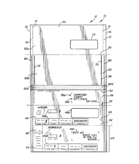
Fig. 1 illustrates a single sheet of paper 10 from
which a two-way mailer 12 of the present invention is
constructed. The sheet of paper 10 includes a first section 20,
a second section 30, and a third section 40. The first and
second sections 20 and 30 are separated by a first transverse
fold line 50, and the second and third sections 30 and 40 are
separated by a second transverse fold line 52. The mailer 12
further includes first and second outer longitudinal tear lines
13 and 14 extending along first and second side edges 16 and 18
of the sheet 10 for defining first and second marginal edge
portions 17 and 19. As will be discussed in further detail
below, the sheet of paper 10 is foldable along the first and
second transverse lines 50 and 52 so that the first section 20
overlies the second section 30 and the third section 40 overlies
the first and second sections 20 and 30.
The second section 30 includes a first severance or
perforation line 32 extending across its width and spaced
parallel to the first and second transverse lines 50 and 52 for
defining first and second portions 34 and 36 of the second
section 30. The first portion 34 includes a sealing panel 60a
and a first side 60b of a return envelope 60. The second side
60c of the return envelope 60 is defined by the first section 20
of the sheet 10. As will be discussed in further detail below,
the return envelope 60 is formed by folding the sheet 10 along
the first transverse line 50, as shown in Fig. 2, and securing
the first section 20 with the second section 30. The return
envelope 60 is severable from the second portion 36 along the
first severance line 32. The second portion 36 preferably
- 2088959
STD 396 PB - 8 -
includes an initial addressee portion 36a having initial
addressee information 36b printed thereon.
A second severance or perforation line 42 is provided
on the third section 40 for defining a return portion 44 and a
window portion 46. The return portion 44 has return addressee
information 44a printed thereon, and the window portion 46
includes a window 46a die-cut or otherwise formed therein through
which the initial addressee information 36b on the second section
36 is visible when the third section 40 overlies the first and
the second sections 20 and 30, see Fig. 3. The window 46a may be
covered by transparent material (not shown) secured to the window
portion 46. The return portion 44 may additionally include
payment information 44b printed thereon, and the window portion
46 may further include receipt information 46b printed thereon.
The first section 20 also includes a cut-out window 22
through which the return addressee information 44a on the third
section 40 is visible when the return portion 44 is separated
from the window portion 46 and a further portion 48 of the third
section 40 and the return portion 44 is inserted into the return
envelope 60, see Fig. 8. The return portion 44 may be separated
from portions 46 and 48 via perforated line 42 and perforated
line 43. Receipt portion 46 may then be separated from portion
48 and the second section 30 via lines 42 and 52.
First securing means comprising first and second lines
of adhesive 70 and 72, respectively, are provided on the second
section 30 for securing the first and the second sections 20 and
30 to one another when the sheet 10 is folded along the first
transverse line 50, as shown in Fig. 2. The secured first and
second sections 20 and 30 form return envelope 60 which can be
used by the initial addressee for transmission of material, such
as return portion 44, to the sender or to another person. The
first line of adhesive 70 is positioned inwardly of and adjacent
to the first longitudinal tear line 13 and the second line of
adhesive 72 is positioned inwardly of and adjacent to the second
longitudinal tear line 14. Alternatively, the first and second
20889S9
STD 396 PB - g -
lines of adhesive 70 and 72 may be positioned on the first
section 20 or may be positioned on both the first and second
sections 20 and 30.
Second securing means comprising third and fourth lines
of adhesive 80 and 82, respectively, are located on the second
and third sections 30 and 40 of the sheet 10, as shown in Fig. 1,
for detachably securing the third section 40 to the first and the
second sections 20 and 30 when the sheet is folded along the
second transverse line 52. The first, second and third sections
20, 30, and 40, upon being folded and secured to one another, as
shown in Fig. 3, form a folded mailer 12 in accordance with the
present invention. The third line of adhesive 80 is positioned
on the first marginal edge portion 17 intermediate the first
longitudinal tear line 13 and the first side edge 16 of the sheet
10, and the fourth line of adhesive 82 is positioned on the
second marginal edge portion 19 intermediate the second
longitudinal tear line 14 and the second side edge 18 of the
sheet 10.
As shown in Fig. 4, it is further contemplated by the
present invention that the sheet 10 may alternatively include
third and fourth lines of adhesive 80' and 82', respectively,
located on only the third section 40 of the sheet 10 for
detachably securing the third section 40 to the first section 20
when the sheet 10 is folded along the second transverse line 52.
Referring again to Fig. 2, the second securing means
further comprises adhesive material 81 located at spaced apart
locations on a back surface 21 of the first section 20. The
adhesive material employed for forming lines of adhesive 70, 72,
80 and 82, and the adhesive material 81 located on the back
surface 21 of the first section 20, preferably comprises
conventional waterbase adhesive material.
The sealing panel 60a, as shown in Fig. 1, is coated
with conventional heat resistant remoist glue material 60a'. The
glue material 60a' serves to secure the panel 60a to the second
20889~9
STD 396 PB - 10 -
side 60c of the return envelope 60 for sealing the envelope 60
closed, as shown in Fig. 8.
The method for forming the two-way mailer 12 of the
present invention will now be described. Initially, a single
sheet of paper, such as shown in Fig. 1, is provided having
appropriate initial addressee information 36b, return addressee
information 44a, and any other desired information printed
thereon. First and second lines of adhesive 70 and 72 are
applied onto the second section 30 of the sheet 10 adjacent to
and inwardly of the first and second longitudinal tear lines 13
and 14. Third and fourth lines of adhesive 80 and 82 are also
are applied onto the sheet 10 along the first and second marginal
edge portions 17 and 19 of the sheet 10, as shown in Fig. 1 or
Fig. 4. The sheet 10 is then folded along the first transverse
line 50 so that the first section 20 overlies the second section
30. The lines of adhesive 70 and 72 interposed therebetween
serve to secure the two sections 20 and 30 together to form a
return envelope 60, as shown in Fig. 2. Adhesive material 81 is
then applied at space apart locations on the back surface 21 of
the first section 20, as shown in Fig. 2. Thereafter, the sheet
of paper 10 is folded along the second transverse line 52 so that
the third section 40 overlies the first and second sections 20
and 30. The lines of adhesive 80 and 82 and the adhesive
material 81 serve to secure the third section 40 to the first and
second sections 20 and 30 when the third section 40 overlies
sections 20 and 30, thereby forming a folded mailer 12, as shown
in Fig. 3.
In order to open the mailer 12, the marginal edge
portions 17 and 19 are removed via the longitudinal tear lines 13
and 14, such as shown in Fig. 5. The sheet 10 is then unfolded
along the transverse line 52, as shown in Fig. 6, so that the
third section 40 no long overlies the first and second sections
20 and 30.
After the mailer 12 has been opened, the return
envelope 60 is removed from the second portion 36 of the second
~088~5~
STD 396 PB - 11 -
section 30 along severance line 32, as shown in Fig. 6. The
return portion 44 is also removed from the remai~ing portions of
the third section 40 along severance lines 43 and 42. The return
portion 44 is then inserted, along with any other desired items,
e.g., a payment check, into the return envelope 60, as shown in
Fig. 7. The return portion 44 is inserted so that the return
addressee information 44a is visible through window 22 in the
envelope 60, see Fig. 8. Remoist glue material 60a' on the
sealing panel 60a is then moistened and the panel 60a is folded
over and secured to the second side 60c of the envelope 60 for
sealing the envelope 60 closed. Thereafter, the envelope 60 is
in condition for remailing to the return addressee. The receipt
portion 46 may also be removed from r~m~ln;ng portions 48 and 36
of the sheet 12 for use as a receipt by the recipient.
An apparatus 100 for folding and gluing a sheet of
paper 10, such as shown in Fig. 1, in order to form a mailer
product in accordance with the present invention, will now be
described. The apparatus, as shown in Fig. 9, comprises a glue
application system 110, a buckle-chute folder 120, and a delivery
system 130.
The delivery system 130 includes a conveyor
132 attached at the infeed of the folder 120. The conveyor 132
includes skewed rollers 134 and ball rollers 136. Skewed rollers
134 are rotatably driven by drive means (not shown), while the
ball rollers 136 are rotatably mounted in a fence 138 positioned
above the skewed rollers 134. Due to the angle at which the
skewed rollers 134 are mounted, the rollers 134 act to urge
incoming sheets 10 towards the fence 138. The sheets 10 are
nipped between the ball rollers 136 and the driven skewed rollers
134 for advancement toward the infeed of the folder 120.
The glue application system 110 includes first and
second separate gluer arrangements 112 and 114, respectively,
which are spaced-apart from one another and positioned above the
STD 396 PB - 12 - 2 0 8 ~ 9 5 9
conveyor 132, as shown in Fig. 9. First and second mounting
bracket arrangements 116 and 118, respectively, serve to
adjustably support the first and second gluer arrangements 112
and 114 on a support bar 113 above the conveyor 132. The support
bar 113 is fixedly connected to the folder by conventional
fastener means (not shown).
Referring now to Figs. 10 and 11, the first gluer
arrangement 112 comprises first and second gluers 140 and 150,
which are also referred to herein as first and second glue means,
which serve to apply two closely spaced lines of adhesive 80 and
70 on a sheet of paper 10. The first gluer 140, as best shown in
Fig. 11, comprises a solenoid actuator 142 having an outer casing
142a with a threaded end portion 142b fixedly connected thereto.
Extending from the casing 142a and passing through the threaded
end portion 142b is a piston 142c having an end portion 142c'
with a threaded opening therein. A nozzle 144 is connected to
the piston 142c for reciprocating movement therewith. The nozzle
144 includes a glue input connector 144a threadedly connected
with an extension portion 144b which, in turn, is connected to
the piston 142c via a threaded end portion which is received
within the threaded opening of the piston 142.
The nozzle 144 receives glue or adhesive material via a
glue line 143 which is mounted over the glue input connector 144a
of the nozzle 144, as shown in Fig. 11. The glue line 143 is
also connected to an intermediate glue line 147 which is gravity
fed with glue or adhesive material from a glue supply 145, see
Fig. 9. The nozzle 144 further includes a spring loaded ball tip
144c which allows glue to flow out from the nozzle 144 when the
tip 144c makes contacts with a workpiece. Therefore, when the
solenoid 142 is actuated by control means (not shown), the piston
142c, and hence the nozzle 144, are driven in a direction toward
the paper 10 causing the spring loaded ball tip 144c to make
contact with the paper 10. Upon making contact with the paper
10, the tip 144c applies a line of glue or adhesive material 80
onto the sheet 10, as shown in Fig. 10.
'~ 2088959
STD 396 PB - 13 -
Referring again to Fig. 11, the second gluer 150
comprises a solenoid actuator 152 having an outer casing 152a
with a threaded end portion 152b fixedly connected thereto.
Extending from the casing 152a and passing through the threaded
end portion 152b is a piston 152c having an end portion with a
threaded opening therein. A nozzle 154 is connected to the
piston 152c for reciprocating movement therewith via a threaded
end portion which is received within the threaded opening of the
piston 152c.
The nozzle 154 receives glue or adhesive material via a
glue line 153 which is mounted over a glue input connector 154a
of the nozzle 154, as shown in Fig. 11. The glue line 153 is
also connected with an intermediate glue line 149, which is
gravity fed with glue from the glue supply 145. The nozzle 154
further includes a spring loaded ball tip 154b which allows glue
to flow from the nozzle 154 when the tip 154b makes contacts with
a workpiece. Thus, when the solenoid 152 is actuated by the
control means, the piston 152c, and hence the nozzle 154, are
driven in a direction toward the paper 10 causing the spring
loaded ball tip 154b to make contact with the paper 10. Upon
making contact with the paper 10, the tip 154b applies a line of
glue or adhesive material 70 on the sheet 10, as shown in Fig.
10 .
The first and second gluers 140 and 150 are mounted in
a staggered relationship, as shown in Figs. 10 and 11, via the
first mounting bracket arrangement 116 to permit the gluers 140
and 150 to apply the lines of adhesive 80 and 70 in close
proximity to one another. The mounting bracket arrangement 116
comprises an upper bracket 160, a lower bracket 162, and an
intermediate support bracket 164. The upper and lower brackets
160 and 162 are connected to the intermediate bracket 164 via
fasteners 166a, 166b and 166c, as shown in Figs. 10 and 11.
The upper bracket 160 includes a threaded opening 160a
therein for threadedly receiving end portion 142b of solenoid
142. A locking bolt 160b is received within the upper bracket
2088959
STD 396 PB - 14 -
160 and extends across a portion of the opening 160a for locking
the end portion 142b in position. The lower bracket 162 likewise
includes an opening 162a therein for threadedly receiving end
portion 152b of solenoid 152. A locking bolt 162b is received
within the lower bracket 162 and extends across a portion of the
opening 162a for locking the end portion 152b in position. The
lower bracket 162 also includes an opening 162c through which the
nozzle 144 extends.
The mounting bracket arrangement 116 is movable along
the cross bar 113 to allow for proper positioning of the gluers
140 and 150 over the conveyor 132. A locking screw 162d passes
through an opening 162e in the lower portion 162 for frictionally
engaging with the cross bar 113 to lock the mounting bracket
arrangement 116, and hence the gluers 140 and 150, in position
along the cross bar 113.
The second gluer arrangement 114 likewise includes two
gluers 114a and 114b mounted on the bar 113 in a staggered
relationship via the second mounting bracket arrangement 118, as
shown in Fig. 9. Gluer 114a is constructed in essentially the
same manner as gluer 140, and gluer 114b is constructed in
essentially the same manner as gluer 150. Consequently,
reference is made to the discussion above regarding gluers 140
and 150 for a detailed explanation of the construction of gluers
114a and 114b.
The second mounting arrangement 118 mounts the gluers
114a and 114b in a staggered relationship to permit the gluers
114a and 114b to apply two lines of adhesive 82 and 72 (see Fig.
1 or 4) in close proximity to one another. The second mounting
arrangement 118 is constructed in essentially the same manner as
the first mounting arrangement 116, and includes an upper
mounting bracket 118a, a lower mounting bracket 118b and an
intermediate mounting bracket 118c. The lower bracket 118b is
mounted to the intermediate bracket 188c in essentially the same
manner that the bracket 162 is mounted to bracket 164, as shown
in Fig. 11. The upper bracket 118a is mounted to the
' 20889~9
.i~
STD 396 PB - 15 -
intermediate bracket 118c so that gluer 114a is positioned closer
to the outer edge 10b of the sheet than gluer 114b.
Brackets 160, 162 and 164 may be substituted for brackets
118a-188c. The upper bracket 160, however, would be mounted to
the intermediate bracket 164 so that fastener 166b passes through
threaded opening 164a in intermediate section 164. As a result,
the nozzle of the first gluer 114a would pass through opening
162f in the lower bracket 162 rather than through opening 162c.
The folder 120, as shown in Figs. 9 and 12, is a buckle
chute folder having four fold rollers 120a-120d, first and second
fold pans 122 and 124, and two sets of cutter and anvil rollers
170 and 172 (only one set is shown in Fig. 12). Such a folder is
commercially available from Baumfolder, Inc., in Sidney, Ohio.
Operation of the apparatus 100 for gluing and folding a
sheet of paper 10 to make a folded mailer 12, as shown in Fig. 3,
will now be explained. The conveyor 132 receives a sheet of
paper 10 and transports the same past the first and second gluer
arrangements 112 and 114 to the infeed of the folder 120. A
photo-cell 190 may be provided for sensing the incoming or front
edge 10a of the sheet. A counterwheel 192 may likewise be
provided for counting, after the incoming edge 10a is sensed by
the photo-cell 190, the length of the sheet 10 that has past
under the first and second gluer arrangements 112 and 114. A
convçntional controller (not shown) is connected to the photo-
cell 190 and to the counterwheel 192 and receives the signalsoutput by these two sensors. Based upon these signals, the
controller controls the actuation of the solenoids associated
with gluers 140, 150, 114a and 114b so as to form lines of
adhesive 70, 72, 80, and 82 on each sheet 10, as shown in either
Fig. 1 or Fig. 4.
As the front edge 10a of the sheet 10 passes the first
and second gluer arrangements 112 and 114, first and second
rollers 120a and 120b of the folder 120 grasp the sheet 10 and
move it into the first fold pan 122. After the front edge 10a of
the sheet 10 hits a stop bar 122a in the pan 122, the sheet 10
20889S9
w
STD 396 PB - 16 -
buckles along a first transverse line 50. The second roller 120b
and the third roller 120c then grasp the sheet 10 along the first
transverse line 50 and fold the sheet 10 along the line 50 to
form the return envelope 60, as shown in Fig. 2. The rollers
120b and 120c further serve to move the sheet 10 into the second
fold pan 124.
Just after the folded edge at line 50 of the sheet 10
hits a stop bar 124a in the second fold pan 124, a third gluer
arrangement 180, shown in Fig. 12, acts to apply adhesive
material 81 on the sheet 10 in a manner as shown in Fig. 2. The
third gluer arrangement 180 includes two or more solenoids 182
(only one is shown in Fig. 12) and a plurality of nozzles 184
(only one is shown) connected, for example, by a manifold 186 and
glue lines 187 to the glue source 145, for applying the adhesive
material 81 onto the sheet 10.
After the folded edge at line 50 of the folded sheet 10
hits the stop bar 124a, the sheet 10 buckles for a second time
along a second transverse line 52. The second roller 120b and a
fourth roller 120d grasp the sheet 10 as it buckles and fold it
along the second transverse line 52 to form the closed mailer 12,
as shown in Fig. 3. The rollers 120b and 120d further serve to
move the sheet 10 into the two sets of cutter and anvil rollers
170 and 172 which serve to cut perforation lines 13 and 14 into
the mailer 12 just before the mailer 12 is ejected onto a tray
174.
Thus, by the present invention a mailer product is
produced from a single sheet of paper material which is folded
after being printed upon and after having adhesive material
applied thereto. Also in accordance with the present invention,
a folder/gluer is employed for applying adhesive material onto a
single sheet of paper and thereafter folding the sheet into the
mailer product of the present invention.
Having described the invention in detail and by
reference to preferred embodiments thereof, it will be apparent
208~959
~,,
STD 396 PB - 17 -
that modifications and variations are possible without departing
from the scope of the invention defined in the appended claims.
The embodiments of the invention in which an exclusive
property or privilege is claimed are defined as follows: