Note: Descriptions are shown in the official language in which they were submitted.
CA 02088963 2003-09-18
LIGHT FIXTURE WITH DETACHABLE REAR MOUNTING BOX
This application is related to application serial no.
2,088,964, filed February 5, 1993, entitled "Light Fixture With
a Reversible Lens with Adjustable Brackets" and to application
serial no. 2,088,962, filed February 5, 1993, entitled "Light
Fixture With Adjustable Bulb and Radiant Heat Dissipating
Reflector".
BACKGROUND OF THE INVENTION
Field of the Invention
This invention pertains to a light fixture with a detachable
rear mounting box. The rear mounting box is affixed to a wall or
similar mounting surface and the initial electrical connections
are made through the mounting box prior to the attachment of the
light fixture thereto.
pescription of the Prior Art
In the prior art, it has been unnecessarily difficult to
mount certain light fixtures as the initial wiring connections
had to be made before the fixture was fully secured to the wall
or ceiling. This was particularly difficult in the case of heavy
light fixtures.
Similarly, the configuration of certain light fixtures made
it difficult to perform the initial wiring connections as parts
of the light fixture would obstruct these tasks.
Additionally, it was particularly difficult to level a heavy
light fixture. Also in the prior art, supply wire connections
needed to be rated for high temperatures because these wires
could come into direct contact with hot electrical components.
These temperature ratings ranged from 105° C. to 200° C. In
addition, the prior art required that photocontrollers be mounted
exterior of the fixture because of their 90° C. temperature
rating.
Additionally, the prior art has not allowed for the simple
conversion from recessed box mounting and wiring to surface
conduit mounting and wiring.
OBJECTS AND SUMMARY OF THE INVENTION
It is therefore an object of this invention to allow an
electrician installing a light fixture to perform initial
electrical connections prior to the installation of the light
fixture.
It is therefore a further object of this invention to allow
an electrician installing a light fixture to perform initial
electrical connections and leveling with a minimum of physical
obstruction.
It is therefore a further abject of this invention to
provide a way to maintain the electrical wires within a small
metal area allowing the supply wire temperature rating to be as
low as 90° C. thereby reducing the installation casts.
It is therefore a still further objective of this invention
to allow for a photocontroller to be mounted interior to the
mounting box allowing it to run within its maximum temperature.
It is therefore a final object of this invention to achieve
the above objects while allowing the easy adaptability from
recessed box mounting and wiring to surface conduit mounting and
wiring.
These and other objects are achieved by providing a light
fixture with a detachable rear mounting box. The mounting box is~
attached to the wall or ceiling prior to the installation of the
remainder of the fixture. All initial electrical connections are
made through the box in the absence of the light fixture. After
the initial electrical connections and leveling is made, the
light fixture is bolted onto the mounting box. An aperture in
~~~~963
the mounting box aligns with a corresponding aperture in the
lighting fixture and the wires are drawn through these apertures
into the lighting fixture.
The aperture in the box through which the wires are drawn is
offset from the center of the box. This allows the box to be
oriented in a first position for recessed box mounting and wiring
wherein the box is substantially recessed within the light
fixture. However, the box can be oriented in a second position
180° from the first pasition so that a substantial portion of the
box is exposed from the top of the lighting fixture thereby
facilitating surface conduit mounting and wiring.
BRIEF DESCRIPTION OF THE DRAWINGS
Further objects and advantages of the invention will become
apparent from the following description and claims, and from the
accompanying drawings, wherein:
Figure 1 is a front plan view of the mounting box.
Figure 2 is a front perspective view of the mounting box
oriented for surface conduit mounting and wiring.
Figure 3 is a front perspective view of the mounting box
oriented for recessed box mounting and wiring (180° from the
orientation shown in Figure 2).
Figure 4 is a front perspective view of the partially open
light fixture as it engages the mounting box in the recessed box
mounting and wiring configuration.
Figure 5 is a front perspective view of the light fixture in
the surface conduit mounting and wiring configuration with the
mounting box after a cover has been mounted.
Figure 6 is a side cross-sectional view of the light fixture.
in the recessed box mounting and wiring configuration. ;
Figure 7 is a side view, partly in phantom, of the light
fixture in the surface conduit mounting and wiring configuration.
3
CA 02088963 2003-09-18
DETAILED DESCRIPTION OF THE PREFERRED EMBODIMENT
Referring now to the drawings in detail, wherein like
numerals refer to like elements throughout the several views,
Figure 1 is a front view of mounting box 11 while Figures 2 and 3
are front perspective views of mounting box 11.
Mounting box 11 is preferably used in conjunction with a
light fixture such as that disclosed in commonly-owned
application serial no. 2,088,964, filed February 5, 1993,
entitled "Light Fixture with a Reversible Lens With Adjustable
Brackets" and application serial no. 2,088,962, filed February
5, 1993, entitled "Light Fixture With Adjustable Bulb and
Radiant Heat Dissipating Reflector".
Mounting box 11 is preferably composed of metal. Mounting
box 11 includes side flanges 12, 14 with mounting apertures 16,
18, 20, 22. Side flanges 12, 14, as joined by upper and lower
lips 13, 15, respectively, engage the mounting surface 200 (see
Figure 6) and apertures 16, 1$, 20, 22 are used to secure
mounting box 1l to mounting surface 200. Apertures 16, 18, 20,
22 are slanted to allow for adjustment of mounting box 11 to a
level. position even if mounting surface 200 includes slightly
inaccurately placed holes. Sidewalls 24, 26, 28, 30 extend
perpendicularly from the plane of side flanges 12, 14. Front
wall 32, parallel to the plane of side flanges 12, 14, is formed
with sides intersecting respective sides of sidewalls 24, 26, 28,!
30 to form cavity 34 therewithin. Cavity 34 is open in the rear ;
portion thereof (that is, there is an opening formed parallel to
front wall 32 between flanges 12, 14 in order to allow access for
electrical wires extending directly from mounting surface 200
such as in Figure 6).
An upper portion ("upper" being used only with reference to
4
the orientation shown in Figure 1) of front wall 32 of mounting
box 11 includes wiring aperture 36 thereby providing communica-
Lion from the outside to cavity 34. The periphery of wiring
aperture 36 includes an outwardly extending lip 38. dip 38
further includes two enlarged portions 40, 42 at opposing corners
of wiring aperture 36 which include bolt apertures 44, 46.
Sidewalls 26 and 30 (see Figures 2 and 3j include side
capped apertures 48, 50, respectively. Mounting box 11 is
provided with threaded cap 54 inserted into side capped aperture
50. A corresponding threaded cap not shown in the drawings is
provided for side capped aperture 48. As shown in Figures 2, 5,
and 7, side capped apertures 48, 50 are uncapped to provide
access for electrical cable 202 when the mounting box 11 is
oriented for the surface conduit mounting and wiring
configuration. However, as shown in Figures 3, 4, and 6, side
capped apertures 48, 50 remain capped when mounting box 11 is
oriented for the recessed box mounting and wiring configuration.
Sidewalls 24, 28 include capped apertures 56, 58,
respectively. Threaded caps 60, 62 are provided in capped
apertures 56, 58 respectively. Front wall includes aperture 59
covered by knock-out 63. As shown in Figures 2, 3, 4, and 5,
threaded caps 60, 62 or knock-out 63 may optionally be removed to
provide an aperture chosen from apertures 56, 58 or 59 for the
installation of a photocontroller 64.
Lndentations 66, 68, 70 are formed at a portion of the
intersections of front wall 32 with sidewalls 26, 28 and 30,
respectively. indentations 66, 68, 70 are used to engage a
bubble level 72 (see Figure 2) during the installation of
maunting box 11 tp assure that mounting box 11 is installed at
the appropriate angle.
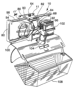
As shown in Figures 4-7, light fixture 10 includes component
assembly 80 and mounting box 11. Component assembly 80 engages
mounting box 11. More particularly, component assembly 80
includes a recessed rear wall 82 with an aperture 84 which is
engaged by lip 38 of mounting box 11. Recessed rear wall 82
further includes raised flanges 86, 88 which include apertures
90, 92 which align with bolt apertures 44, 46 allowing component
assembly 80 to be secured to mounting box 11 by means of bolts
94, 96 as shown in Figure 4. Grounding lug 95 is further
included on component assembly 80.
Component assembly 80 further includes rear wall 98 which is
immediately adjacent to the mounting surface 200. As shown in
Figure 7, there is preferably a one half inch air gap between
rear wall 98 and mounting surface 200 for air flow to cool the
fixture including component assembly 80 (this is in contrast to
most conventional fixtures which mount flush to the mounting
surface). Rear wall 98 further provides a mounting surface for
capacitor 100 and ballast 102. Component assembly further
includes bulb 104, reflector 106, lower clear lens 108 and upper
opaque cover 130.
In order to facilitate the orderly installation of apparatus
10, mounting box 11 and component assembly 80 are preferably
packed in separate compartments of the same shipping box (not
shown). This allows an apprentice electrician to install the
mounting box, and the master electrician to perform the final
wiring while keeping all pieces of apparatus 10 in order.
To use the apparatus described herein, before or after '
optionally installing photocontroller 64 (those skilled in the
art will realize that the order of steps given is illustrative
only, and may be changed), the user first mounts mounting box 11
on mounting surface 200 such as a wall. Mounting box 11 may be '
mounted in a first orientation for the surface conduit mounting
6
~~~~9~
and wiring configuration as shown in figure 2 wherein electrical
power is supplied via conduit 202 through side apertures 48, 50
with caps 52, 54 removed). Alternately, mounting box 11 may be
mounted in a second orientation for recessed box mounting and
wiring as shown in Figure 3 wherein electrical power is typically
supplied from wires extending directly from mounting surface 200.
The user may use bubble level 72 within indentation 68 to assure
the proper placement of mounting box 11.
The user then engages component assembly 80 against mounting
box 11 so that aperture 84 on recessed rear wall 82 of component
assembly 80 extends around the periphery of lip 38. The user
secures component assembly 80 to mounting box 11 using bolts 94,
96.
The user/electrician performs the appropriate wire splicing
with a view towards ground lug 95 on component assembly 8o being
used.
The user then makes the appropriate electrical connections
to capacitor 100 and ballast 102 according to all electrical
safety codes plus the current National electric Codes. To the
extent possible, the user tucks all wires into cavity 34.
Finally, the user assembles any final mechanical aspects of
component assembly 80.
Thus the several aforementioned objects and advantages~are
most effectively attained. Although a single preferred
embodiment of the invention has been disclosed arid described in
detail herein, it should be understood that this invention is in
no sense limited thereby and its scope is to be determined by
that of the appended claims.
7