Note: Descriptions are shown in the official language in which they were submitted.
: ;
2~9~3 - :~:
:.
~...... ............................................................. ..... .
HOl: LOW MEMBERS CONNECTOR
FIELD OF THE IN~ENTION
,.
This invention relates to an improved method and
means of connecting hollow members.
More particularly, lt relates to a method and -~
means for connecting one hollow member to the end of
another hollow member with the connection being made
internally of the first hollow member.
A partlcular application of the invention is the
securement of a hollow roofing member to a hollow wall
member in the erection of modular building structures.
BACKGROU~D ;{' ~ y~9
'
In copending U.S. Application Serial No. ~
07/792,356, filed November 14th, 1991, there is disclosed a ~ -
connection in the form of a wedge arrangement employing a
tapered block for securing a hollow roof panel to a hollow
wall member in a modular building structure.
In such connection, if the wedge is driven under
too much force damage can occur and the connection cannot
be released should it be required to replace the roof
panel. If the wedge is driven too lightly, the connection
may bec~ome loosened under shock or vibration. Further the
.~ .
DSJ:af 8591
- 2 - ~0~023
connection can only be made through the open end of the
hollow roof panel and not at intermediate points up the
roof.
The present invention provides a connecting
system and hardware therefor in which in each case a
consistent wedging action can be obtained by unskilled
workmen and the connection can be released if the connected
member needs to be replaced.
Sl~MMARY OF THE INVENTION
According to the invention the connecting means
comprises a metal anchor member to be inserted into and
secured in the end of a first hollow member such as a wall
member with the anchor member having an end extension
projecting out of the said hollow member and adapted to
project through an opening into the interior of a second
hollow member such as a roof member overlying the end of
the first hollow mernber, said anchor end extension having a
transverse passage therethrough, a stop member preferably
in the form of a pin for insertion through said passage to
project on opposite sides thereof, and a metal wedge member
adapted to embrace said end extension on opposite sides
thereof beneath said stop member and shaped to exert a
clamping pressure when forced inwardly relative to said end
extension to a stop position. -
According to one form of the invention, said
metal wedge member comprises a bifurcated wedge adapted to
straddle said anchor end extension beneath said stop :`~
member, and a spring is provided for interposing between
said wedge member and said stop member.
According to this form of the invention, the
bifurcated wedge member has spaced runners for sliding on
DSJ:af/ 8591
- 3 - 2 ~ 8 9 0 2 ~ - ~
,
i the interior surface of the second hollow member, spaced
ramps leading up from the front of the runners to a rear
wall connecting the runners, and the spring is formed to
be sleeved onto the anchor end extension beneath the stop.
Again, according to this form of the invention,
the spaced ramps are serrated, the spring comprises a plate
of spring material having downturned ends to engage in the
ramp serrations, and a washer is provided to be sleeved
onto the end extension and located between the spring plate
and the stop member.
I Again, according to this form of the invention,
the wedge member has an upturned flange rearwardly of the
inclined ramps to provide an engagement member to be
gripped for retracting the wedge.
n another aspect of the invention, the wedge
comprises a metal plate having a slot arrangement whereby
said wedge is adapted to be sleeved over the end of said
anchor extension and beneath the said pin stop and to be
advanced inwardly beneath said pin, said plate having a
camming surface to effect a clamping action on the members
to be connected as the wedge is advanced inwardly beneath
the pin.
Further, the said wedge plate preferably is
provided with detent means for cooperation with the stop
pin with the plate in its innermost position and with a
flange formation to form a gripping surface when it is
desired to retract the wedge.
DSJ: af / E~591 .
~902~
BRIEF DESCRIPTION OF THE DRAWINGS
These and other features of the invention will
become apparent from the following detailed description
taken in conjunction with the accompanying drawings in
which Figure 1 is a broken away perspective view of a
building structure formed by interconnected hollow wall and
roof panels for which the invention is particularly
applicable.
Figure 2 is a broken away elevational view
illustrating the manner of connecting the end of a hollow
roof member to the upper end of a hollow wall member in
accordance with one form of the invention.
Figure 3 is an enlarged part vertical sectional
part elevational view showing the initiation of the wedge
connection located internally of the hollow roof member
preparatory to clamping the end of the roof member against
the sloping surfaces presented at the upper end of the
hollow wall member.
Figure 4 is a part sectional part plan view
illustrating the wedge in locked clamping position.
Figure 5 is an exploded perspective view ;
illustrating the components of the connecting means of the
invention in association with a corner wall cap for
securing a hollow roof panel to the hollow wall member at
the corner of a modular building.
Figure 6 is an enlarged perspective view of the
anchor member of the invention connecting means.
Figure 7 is a broken away elevational view
showing the anchor member anchored by an anchor rod to the
concrete base of the building.
DSJ:af/ 8591
-. ::: : - , ,
::- ~: . ~ : . . :~ :: , ::
- 5- 208~0~3
i Figure 8 is a perspective view illustrating the
.. positioning of the anchor member in the box connector in a
gabled end wall at a point intermediate the height of the
gable and showing a wall cap ready for assembly.
igure 9 is a perspective view showing the end
wall cap in position ready to receive a box connector
forming part of the roof panel.
Figure 10 is a broken away perspective view of
the wedge plate ready for assembly with the anchor and stop ~:
pin to secure the roof member and the wall cap to the top
of the end wall gable in accordance with this aspect of the
invention.
`
- '.
.
. .:
~ ,
" ~'';'.''~
, ~ ~
' ' ~ - .
. :-. .~
.: .
DSJ:af/ 8591
2089023
3 DETAILED DESCRIPTION OF THE PREFERRED EMsQDIME~Ts
igure 1 illustrates a building structure for
which the present invention is particularly applicable.
AS illustrated, the structure has walls made up of
prefabricated wall panels 1 joined at the corners by box
connectors 2 and intermediate the corners by box connectors
2', prefabricated roof panels 3 ending in box connectors 4,
at the edges of the roof and connected intermediate the
roof edges by box connectors 4~. The edges of the roof
are finished by facia members 5. The wall and roof panels
and the box connectors are of hollow rectilinear form and
are adapted for interlocking connection.
..;
Such a building structure is now practical with
the wall panels 1, roof panels 3, and box connectors 2,2~,
4 and 4' being extruded from thermoplastic materlal and, as
illustrated in the enlarged view in Figure 3, being
extruded to provide a reinforced thermoplastic substrate 6
having a co-extruded smooth skin 7 overlying the exposed
surfaces of the substrate in accordance with the invention
disclosed in copend~ng Canadi.an Application Serial Mo.
2,070,079-3. ::
The wall and roof panels are of similar
rectilinear configuration having internal webs 8 and end
grooves 9 as illustrated in Figure 5. As illustrated in
Figure 5,the corner box connector 2 is provided with wall
extensions 10 terminating in inturned flanges 11 on
adjacent sides 12 and 13 for engagement in the wall panel
grooves 9 to form a corner interlock between the wall
panels 1.
It will be understood that the connectors 2~ and
4~ will have similar wall extensions and locking flanges
DSJ:af/ 8591
q - 7 -
2~Q~3
: for connecting the wall panels in an aligned relationship
rather than in a corner relationship.
t is desirable that the roof panels be mounted
5 at a slope and, by way of example, the securement of a roof
panel at the corner of the building structure will first be
described. For this purpose, the wall member in the form
of the interlocked corner box connector 2 has mounted on
the upper end thereof a cap 14 presenting sloping roof
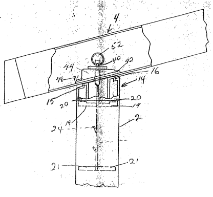
10 panel bearing surfaces 15 and 16.
The cap preferably comprises an injection molded
member adapted to seat down on the top of the corner box
connector 2 as hereinafter more particularly described.
15 Intermediate the corners it will be understood the cap for
providing the sloping roof panel bearing surfaces may
comprise an elongated extruded member seating down on the
top of the wall panels 1 and their box connectors 2~.
¦ 20 It will be understood that the building
structure may be quickly assembled by interconnecting the
wall and roof panels with their respective box connectors
and cement or other materlal may be introduced into the
hollow wall panels for permanency of the structure and the
roof panels may contain insulation if desired.
In the particular context of a building -
structure such as described, the present invention provides
an advantageous means of securing the roof panels to the
capped wall panels to effect a controlled secure connection
while affording a means of releasing the connection should
the roof panel require replacement for any reason.
In this connection, there is provided an anchor
member preferdbly formed of metal generally designated at
17 in Figure 6 provided with a generally flat main body 18
having upper arms 19 which extend parallel to each other in
opposite directions and offset by the width of the body 18.
DSJ:af/ 8591 :
~;
~ - 8 -
- 2~89023
The arms 19 are provided at their outer ends with outwardly
projecting locating finger mounts 20 which are adapted to
overlie the corners of the box connector 2 to provide a
fixed vertical position for the anchor member when it is
inserted into the box connector 2.
:
At the lower end, the anchor is provided with -~-
offset parallel orienting arms 21. ~ ;~
:~
The arms 21 are offset substantially 90 degrees
from the arms 19 and extend into the corners of the box
connector 2 which are at 90 degrees to the corners over
which the fingers 20 lie.
The anchor 17 is provided with an upper end -~
extension 22 which is of U-cross section and is provided at -
its distal end with aligned pin receiving openings 23 in ;
the opposite walls of the U.
The main body of the anchor 18 is provided with
a series of outturned locking tangs 24.
To effect the connection between a roof panel
and a capped connector or wall member, as illustrated in
Figure 5, the anchor member 17 is lowered into the
connector 2 until the fingers 20 rest on top of the corners
of connector 2 one finger at the corner of the building
structure and the other at the opposite corner of the box
connector 2. The anchor is oriented in this position and
held in oriented position by the arms 21 extending into
opposite corners of the box connector 2 at right angles to
the corners over which the fingers lie. The orientation of
the anchor is such that the open face of the U-extension 22
faces up the slope of the roof.
The anchor member 17 is then anchored in place
in the connector 14 by introducing concrete or the like 25
into the connector 2 with the locking tangs 2g embedded in
the concrete.
DSJ :af / 8591
- 9 -
2~0~
The cap 14 has a central opening 26 to allow lt
to be sleeved down over the upper end of the anchor 17 into
its capping position with the U-shaped end extension 22
standing proud above the bearing surfaces 15 and 16 of the
cap.
Cap 14 is provided with outturned ledges or
flanges 27 adapted to rest on the upper edges of the bo~
10 connector 2 and depending right angular arms 28 adapted to -:
straddle the anchor fingers 20 and abut against the right
angular walls of connector 2, it being understood that
sufficient clearance with the concrete 25 will be provided
for introduction of the locating and orienting connector
arms 28.
The cap 14 is of generally cruciform shape with
the extending arms 29 thereof being hollow and carrying the
ledge seats 27 at the lower ends thereof.
These cruciform arms are braced by horizontal ;.
triangular webs 30 which overlie the locating arms 28 and : :
the anchor fingers 20.
sy virtue of having the cruciform arms 29 hollow
wiring may be sleeved therethrough if desired to run wiring
around the roof line. Further, the arms 29 are cut away
as at 31 and provided with apertured inwardly projecting`
fingers 32 to provide for an interlock with mating elements
of a closure plate (not shown).
The roof panel 3 to be secured to the top of the
wall to seat on cap 14 has its box connector 4 provided :
with an opening 33 so that it can be lowered down over the
anchor extension 22 to rest on the cap bearing surfaces 15
and 16.
- - ~ :
DSJ:~f/ 8Sgl :
s~ ~ 2 ~ ~ ~ 0 2 ~ ~
Spring member 34, lllustrated particularly in
Figure 5, comprising a plate like member of spring steel or
the like, having a central U-shaped slot 35, is then
sleeved down over the U-shaped end of the anchor extension
22.
:
Spring member 34 has downwardly and outwardly ~ ~
turned projections 36 which when the spring is slee~ed onto : ::^
3 the extension 22 are oriented one facing the downward slope ~:~
10 of the roof and the other facing the upward slope of the ;
roof. A washer member 37 of steel or the like provided ~::
with a central U-slot 38 is then sleeved down on the U-
: shaped anchor end extension 22 to overlie the spring member
34. Washer 37 has reinforcing downturned edges 39
15 disposed in right angular relation to the downturned spring :
projections 36 and projecting downwardly on opposite sides
of the spring member. A removeable pin 40 preferable of
metal is then inserted through the apertures 23 at the .
upper end of the extension 22 to form a stop against upward
20 movement of the spring and washer members.
The securement of the roof panel or member to
the bearing surfaces of the wall cap is then effected by a
bifurcated wedge mernber which may be formed as a metal :~:
25 stamping which is generally designated at 41 and shown
particularly in Figure 5. The wedge member 41 has a pair
of spaced runners 42 pro~ided with reinforcing ribs 43
which are adapted to slide on the interior surface of the
hollow box connector roof member 4.
Extending upwardly from the front of the runners
42 are spaced ramps 44 which are joined at their rear as at
45 and connected to the base 46 of the runners by the rear
wall 47.
The base of the runners is extended rearwardly
to an upturned flange 48 through which forces may be
DSJ:af/ 8591
- 11 - 20~9~2~
exerted to drive the wedge inwardly for locking engagement
or withdraw it for unlocking engagement.
The upper surfaces of the ramps 44 and
connecting surface 45 are serrated as at 49 and the slot 50
defined between the ramps 44 is slightly narrowed at 51 to
provide a slight restriction to the passage of the anchor
extension 22 therethrough giving the slot a keyhole ~,~
appearance. ~ ~-
'''~
To effect the locking or clamping action between
the hollow roof member 4 with the facia member 5 removed
the roof member is sleeved over the anchor extension 22. , '
Working up through the open lower end of the hollow member , ~ ~'
4 the spring and washer are sleeved onto the extension 22
and the pin is put in place. The wedge 41 is then inserted ;~
into the ,open end of the roof member and beneath the spring
member 34.
` The wedge member is then pushed inwardly sliding ,~
on its runners on the interior surface of the roof member 4 '~
with the ramps 44 straddling the extension 22. The inward ' ~'`
movement of the wedge effects movement of the extension 22 -~ ;
up the slot 50. ..
''~
The wedge is driven inwardly until it meets the
interference at the slot restriction 51. On further
movement, there is sufficient resiliency in the U-shaped
extension 22 and the walls of slot 50 to allow the relative
movement between the end extension 22 and the wedge to
bring the wedge to the final position as illustrated in
Figure 4 while at the same time giving an audible click or
sna,p as the slot restriction is passed. ThiS click or snap
is sufficient to alert the installer that the connection ',
35 has been made with the proper clamping forces between the ''
roof member 4 and the cap member 14. ;~
DSJ:af/ 8591
- 12 - ~ 02~
¦ The downturned ends or projections 36 of the
¦ spring member 34 locate in the serrations 49 to bar wedge
movement under shocks or vibration.
To release the connection, pin 40 can be removed
by means of ring 52 allowing the spring and washer to be `
sleeved upwardly on the extension 22 and the wedge removed
by pulling on the wall 48.
`
While the anchor 17 embedded in the concrete
filling the box connector 2 should provide sufficient ~-
anchorage against lifting of the roof panel under wind
loading but if desired, as shown in Figure 7, the anchor
member 17 may be further secured by an anchor rod 53 ~
15 extending down into the concrete pad 54 on which the ~ `
structure is adapted to be built and secured.
Figures 8 to 10 illustrate the manner of
securing the roof at an intermediate point or intermediate
points up the gable of the building structure.
As illustrate in Figure 8, the anchor member 17
is arranged in an intermediate box connector 2' but
oriented so the holes 23 thereof are aligned longitudinally
of the wall.
In this case a pin 40' inserted through the
openings 23 has its end portions 40" deformed to follow the
slope of the gable.
It will be understood that the anchor 17 will be
secured in position by pouring of concrete into the box
connector 2~ it occupies.
i
To provide a bearing surface for the roof
structure there is provided an extruded end wall cap 55
having closed cells 56 and 57 extending longitudinally
thereof and spaced walls 58 projecting downwardly therefrom
DSJ:af/ 8591 .:
`:?' ``
~l - 13 - 2~8~0~
to embrace opposite faces of the wall panels 1 and box
~, connector 2' of the end wall gable when seated down on top -
. thereof. The end wall cap 55 has an opening 55~ through
the underside thereof to receive the end extension 22 of
the anchor and its pin 40' as the wall cap is seated down
on top of the end wall of the building structure.
Further the end wall cap 55 has longitudinally
extending chambers 59 on opposite sides thereof with the --
chambers being open to the sides as indicated at 60 with
the edges of the open sides being turned inwardly at 61 to
provide for locking engagement with a suitable mating
closure member which may take the form of weather
stripping, or other desired closure configuration. Above
the chambers 59, the end wall cap 55 is provided at
opposite sides thereof with longitudinally extending
grooves 62 adapted to receive the inturned flanges 63 of
the roof box connector 4 to securely interlock same. The
box connector 4 is provided on its undersurface with an
20 opening 64 to accept the pinned end 22 of the anchor with - ~ `-
the pin 40~ standing proud above the bottom surface of the
box connector.
The outer wall 65 of the box connector 4 is cut
away at 66 to expose the pinned end of the anchor and a
registering notch 67 is cut into the outer lower flange 68
to allow for the insertion of the metal wedge plate 69.
As illustrated in Figure 10, this wedge plate is provided
with a slot arrangement 100 in the form of a cross and is
slightly bent intermediate of its length and provided at
one end with a handle flange 70.
It will be understood that the wedge plate 69 ~-~
can be introduced into the box connector 4 with the lateral
35 portion of the slotted cross registering with the pin 40' ~ ~
allowing the plate to be sleeved down over the end 22 of -
the anchor and over the pin 40' to a point beneath the pin
and bearing on the undersurface of the box connector.
DSJ:af/ 8591
' ::
~ ,- 14 2089023
The wedge plate may then be pushed inwardly with
the bend in the plate forming a camming surface to tighten
the box connector down onto the end wall cap and onto the
u~ 5 top of the gabled wall to provide an intermediate roof
anchor.
Wedge plate 69 is also provided with holes or
detents 71 on opposite sides of the slotted cross adjacent
10 to the handle flange 70 into which the end portions 40" of .
the pin 40' may drop when the wedge plate is fully home.
The handle flange 70 provides the means of
' extracting the wedge plate under a pulling force should it
15 be desired to replace the roof structure. -~
While the preferred embodiments of the invention
has been described in detail, it will be understood by
those skilled in the art that variations in detail and
application may be made without departing from the spirit
of the invention or the scope of the appended claimis.
DSJ: af / 8591 :