Note: Descriptions are shown in the official language in which they were submitted.
7.82-077-0
~'~TLE OF THE INVENT;~ON
IMPROVED CRYOGENIC DISTII~L~ATION PROCESS
FOR T~3E PRODUCTION OF 0?CYGEN AND NITROGEN
BACKGROUND OF TI3E INVENTION
Field of the Tnventa_on
The present invention relates to an improved cryogenic
distillation process for the production of oxygen and nitrogen
and the integration thereof with. a gas turbine.
Description of the Backcround
A conventional process for cryogenic separation of air
components entails two distillation columns, one being a
higher pressure column having the upper end in heat exchange
relation with the loiter end of a lower pressure column. Cold
compressed air is separated into nitrogen-rich and oxygen-rich
liquids in the higher pressure column. Thereafter, these
liquids are fed to the lower pressure column to yield an
oxygen product and a nitrogen product. This process is most
efficient when the oxygen pressure is relatively loss, on the
order of about 1 to 2 bar.
U.S. Patent 4,22~&,04~ describes the use of air derived
from a poorer turbine as air feed for an oxygen plant using a
conventional t~ao column process. Since the optimum air
pressure of a poraer turbine is quite high, such as l0 to 18
bar absolute, the ~;onventional/classical double column process
must operate under elevated pressure in the high pressure
~0~~~~~
_?_
column and low pressure column, thus, producing oxygen and
nitrogen under pressures of 2 to 7 bar absolute. Relatively
good overall efficiency is achieved when the nitrogen product
as well as the oxygen product are recompressed to higher
pressure for further integration with the associated process,
such as coal gasification, and direct reduction for steel
making or power generation, for example.
Unfortunately, this process has a major drawback in that
the oxygen recovery is quite poor when the double column
process is operated at elevated pressure. For example, an air
pressure of 16 bar will yield an oxygen recovery of about 90%
for 95% oxygen purity and about 5 bar absolute oxygen
pressure. For 98% oxygen content, the recovery drops to about
80% for the same air and oxygen pressure. Conventional air
separation plants operated at 6 bar absolute air pressure
typically yield a recovery in excess of 99% of a purity of
about 99.5%. The low recovery results in higher power
consumption and larger equipment sire.
U.~. Patent 3,731,495 describes a two column apparatus
and process for air separation with a nitrogen-quenched power
turbine. In this process, air is separated by low temperature
rectification using a 3.50-400 psia. column and a 45-1.40 psia.
column with nitrogen-rich gas from the latter quenching hot
combustion gas prior to work expansion of the resulting
intermediate temperature gas mixture. However, as this
~~~~~~3
-3-
process uses a double column, it suffers from the same
disadvantages as that of U.S. Patent 4,224,045.
U.S. Patent 4,947,649 describes a single column process
with a nitrogen recycle stream. In this process high pressure
air is condensed at the bottom of than column and is fed
directly to the column. The nitrogen product is compressed
and a fraction is recycled back to the process to serve as
additional reboil and reflux for the distillation column. The
product recovery can be adjusted by varying the recycle flow
rate. This process yields only a small improvement of about
2~ in overall power consumption over the process disclosed in
U.S. Patent 4,224,045.
Thus, a need exists for a cryogenic distillation process
and apparatus for the production and apparatus of oxygen and
nitrogen at elevated air pressure. A need also exists for
such a process and apparatus which can be used efficiently in
combination with a gas turbine.
SUGARY of THE IN~IENTION
Accordingly, it is an object of the present.invention to
provide an improved cryogenic distillation process and
apparatus for the production of relatively high pressure
oxygen and nitrogen products at elevated feed air pressure.
It is also an object of this invention to provide an
improved cryogenic distillation process and apparatus for the
~~~~~.~~~~3
_a_
production of oxygen and nitrogen resulting in a reduced power
consumption and smaller equipment sire.
It is, moreover, an object of the present invention to
provide an improved process for the production of oxygen and
nitrogen whereby the totality or a fraction of the feed air
can be deriaed from a power turbine.
The above objects and others are provided by a cryogenic
distillation process for the production of oxygen and
nitrogen, which entails:
a) cooling at least a fraction of a cleaned, dried and
compressed feed stream containing at least oxygen and nitrogen
and introducing the same into a high pressure column, and
separating the same into a nitrogen-rich liquid stream at the
top of.the column and an oxygen-rich stream at the bottom of
the, column, wherein the overhead of the high pressure column
exchanges heat with both the bottom of the low pressure column
and the bottom of aw intermediate column,
b) introducing the oxygen-rich stream into said
intermediate column to afford a top liquid fraction A and a
bottom liquid fraction B, the overhead of the intermediate
column exchanging heat with the low pressure column at a
location above the bottom reboiler of the low pressure column,
wherein the pressure of the intermediate coluian is lower than
the high pressure column but higher than the low pressure
column,
~~~~0~3
_5_
c) introducing liquid fractions A and S into the low
pressure column as feed,
d) feeding the nitrogen-rich liquid of step a) to the
low pressure column as reflex, and
e) recovering an oxygen~rich stream product at the
bottom of the low pressure column and a low pressure nitrogen-
rich stream at the top of the low pressure column.
DRIEF DESCxtIPTION OF TIDE DRAWTNGS
Figure 1 illustrates an embodiment of the present
invention using a stacked three column arrangement.
Figure 2 illustrates an alternative embodiment of the
present invention using a side column.
F~.gure 3 illustrates the general integration of an air
separation facility with a power turbine in accordance with
the present invention.
Figure 4 illustrates an alternative arrangement where the
condenser of the intermediate column is detached from the low
pressure column.
Figure 5 illustrates the McCabe-Thiele diagrams for the
present three-column process and the conventional two-column
process.
DETAILED DESCRIPTION OF Tk3E P12EFEFtRED EMSODII~EP1T
In accordance with the present invention, an improved
cryogenic distillation process for the production of oxygen
~~~3~~r~
-6-
and nitrogen is provided wherein a significant and
advantageous reduction of power consumption and equipment size
is attained.
In accordance with the present ~.nvention, it has been
discovered that the use of a three-column process, as opposed
to a conventional two-column process, affords a surprising
improvement in oxygen recovery and power savings when elevated
feed air pressures are available and when the products are
needed at relatively high pressure. More particularly, the
present process treats an the oxygen-rich liquid produced from
a high pressure column in an intermediate column before
distilling the resulting products in a final low pressure
column.
The present .invention is advantageous as the totality or
a fraction of feed air can be derived from a power turbine.
In order to restore the balance, nitrogen products from a
cryogenic separation unit may b~e recompressed for reinjection
into the power turbine loop. For example, compressed nitrogen
may be mixed with air feed to a power turbine upstream of a
combustion chamber before expansion for power recovery.
Further, compressed nitrogen may be injected into a combustion
chamber of a power turbine. also, coanpressed nitrogen may be
mixed with hot gas exiting the combustion chamber before
expansion for power recovery.
By adding an a.ntermediate column, it has been
surprisingly discovered that the recovery of oxygen is
significantly improved in a process where the feed air is
available at relatively high pressure, and the products are
needed at relatively high pressure. Further, an excellent
recovery of oxygen can be obtained in a manner whereby power
consumption and equipment size is advantageously reduced.
In more detail, the intermediate column used in
accordance with the present invention has the lower end
thereof in heat exchange with the top of the high pressure
column, and has the upper end thereof in heat exchange with
an intermediate location above tine bottom tray of the lower
pressure column. This intermediate column separates the
oxygen-rich liquid produced at the bottom of the high pressure
column into two liquid fractions which are then introduced as
feeds ~o the low pressure column. The low pressure column
still leas the lower end thereof in heat exchange with the top
of the high pressure column, therefore, its pressure will be
essentially the same as the low pressure column of a classical
double column process operated at the same air pressure.
Further, the nitrogen°~ich liquid produced at the top of
the high pressure column is introduced as reflux to the low
pressure column. By performing an extra step of distillation
in the intermediate column, it is found that the subsequent
distillation in the low pressure column becomes much more
efficient. A comparison of the ~cCabe-Thiele diagrams of the
tw~-column process versus the present three°column process
illustrates the advantageous improvement of the present
_8_ ~f~~~~~
invention, i.e., the aperating ?roes of the three-column
process are closer to the equilibriuxa curve indicating a much
more efficient process. See Figure 6i.
Tn more detail, the process of the present invention may
be described as follows.
The feed stream may be cleaned, dried and compressed in a
conventional manner to remove carbon dioxide and water.
As used herein, the term °'feed stream" means any gas
mixture containing at least oxygen and nitrogen. For example,
atmospheric air may be used as well as off-gas mixtures
containing nitrogen and oxygen. Other gases, such as argon
may, of course, also be present in the gas mixture.
Then, the clean, and dry and compressed feed stream is
cooled and introduced into high pressure column, where it is
separated into a nitrogen-rich vapor stream at the top and an
oxygen--rich liquid stream at the bottom. The nitrogen-rich
vapor at the top of the high pressure column is condensed at
the bottom of both the low pressure and intermediate columns
to form a nitrogen-rich liquid. A fraction of this liquid is
used as reflex for the high pressure column and the remaining
fraction of this liquid is fed to the low pressure column as
reflex. Of course, some of this liquid may be recovered as
product. A fraction of nitrogen-°ra.ch vapor at the top of the
high pressure column can be recovered as medium pressure
nitrogen product. The overhead of the high pressure column
- ~I~~'~a~~
exchanges heat with both the bottom of the low pressure column
and the bottom of the intermediate column.
Thereafter, the Oxygen-rich liquid stream is then
optionally cooled and introduced into the intermediate column
to yield a top liquid fraction A and .bottom liquid fraction B.
The overhead of the intermediate column exchanges heat with
the low pressure column at a location above the bottorr~
reboiler of the low pressure column. The pressure of the
intermediate column is lower than that of the high pressure
column but higher than that of the low pressure column.
Then, either a totality or a fraction of liquid fractions
A and B are introduced into the low pressure column as feed.
If desired, liquid fractions A and B may be cooled prior to
introduction into the low pressure column.
Finally, an oxygen-rich stream product is recovered at
the bottom of the low pressure column and a low pressure
nitrogen-rich stream is recovered at the top of the low
pressure column.
For process refrigeration, it is acceptable to use any
conventional arrangement, such as air expansion or nitrogen
expansion, for exa~aple.
Generally, the air pressure for the feed stream in step
a) after compression is in a range of about 8 to 20 bar
absolute, with the preferred range being about 10 to 18 bar
absolute. The intermediate column pressure will normally be
at a pressure of about 3 to 15 bar absolute, with a preferred
~~~3~Oai~
-lo-
range of about 5 to 13 bar absolute. The low pressure column
generally will have a pressure of about 1 to 8 bars absolute,
with 2 to 7 bars absolute being preferred.
Generally, in introducing the clean and dry compressed
air to the high pressure column, the high pressure column is
maintained at the same pressure as in step a). The air feed
is maintained close to the dew point.
The oxygen-rich stream product may, after recovery, be
recompressed for further use.
Additionally, in accordance with the present invention it
is advantageous if all or at least a fraction of the air feed
stream is provided from a power turbine. ~fowever, many other
embodiments of the present invention are also advantageous.
Far example, it is advantageous to recompress at least a
fraction of the low pressure nitrogen-rich stream of step f)
for further use in an associated process, or to mix the
recompressed nitrogen-rich stream with air feed to a power
turbine upstream of a combustion chamber before expansion for
power recovery.
Moreover, it is also advantageous to inject the
recompressed nitrogen-rich stream into a combustion chamber of
a power turbine, or to mix the recompressed nitrogen-rich
stream with hot gas exiting a combustion chamber of a power
turbine for power recovery.
Furthermore, i.n accordance with the present invention, it
is advantageous if the recompressed nitrogen-rich stream is
-11-
heated in an associated process before being expanded in a
power turbine for power recovery.
Also, it has been found advantageous in accordance with
the present invention to also treat at least a fraction of the
oxygen-rich liquid stream in the intermediate column to
produce extra feeds fox the low pressure column.
Further, in accordance with another aspect of the present
invention, a cryogenic distillation process is provided for
the production of oxygen and nitrogen, which comprises:
a) cooling at least a fraction of a cleaned, dried and
compressed feed stream containing at least oxygen and nitrogen
and introducing the same into a high pressure column, and
separating the same into nitrogen-rich stream at the top of
the column, wherein the overhead of the high pressure column
exchanges heat with both the bottom of the low pressure column
and the bottom of an intermediate column:
c) introducing the oxygen-rich stream into the inter-
mediate column to afford a top liquid fraction A and bottom
liquid fraction B, vaporizing a fraction of said liquid
fraction B in the overhead condenser of the intermediate
column to condense the overhead stream of the intermediate
column, and then feeding the vaporized fraction of the liguid
fraction B and the remaining fraction of the liquid fractian B
to the low pressure column; and
d) introducing the liquid fraction A into the low
pressure column as feed.
CA 02089053 2002-12-19
_ y2 _
The present invention will now be further illustrated
by reference to an example which is provided solely for the
purpose of illustration and is not intended to be
limitative.
In accordance with all the processes and apparati of
the present invention, trays and/pr structured paekings can
be used se mass transfer means between the liquid and gas
fractions in the various columns.
As used herein, the term "tray" refers to any means or
device for effecting intimate contact and mass transfer
between a descending liquid phase and ascending vapor
phases. These various tray axe well known to tY~ope skilled
~.n the art .
The term utray" as used herein also includes means
known such as structured packing or equivalent means which
are devices equivalent to trays to effect such intimate
contact for cryogenic air separation. Examples of
structured packing are disclosed, e.g. in u.s. Patents
2,047,444 4,186,156 and 4,296,050, and Ellis et al_ Trans.
Instn. Chem. Engrs., 42, 1963, known as Goodl4e paCkings.
such structured packing is known as means to promote liquid
and/or vapor mixing in a direction perpendicular to the
primary flow direction, i.e. the vertical direction.
FurthEr~nore, a combination of trays arid packing can be used
as mass transfer means.
Example
~~c~~'~J~
-13 ~-
The cryogenic distillation process of the present
invention can be compared to the process of U.S. Patent
4,224,045.
Tn the following example, the same air feed pressure of
about 1& bars absolute is used for both processes, and the
same product from cold box pressure is used for both
processes, i.e., about 5 bar absolute. Also, the following
assumptions are made:
1) that air is compressed from barometric pressure to
the required pressure,
2) that the oxygen product is compressed from a cold
box outlet pressure to 35.5 bar absolute,
3) that the nitrogen product is compressed from the
cold box outlet pressure to the same pressure as the feed, and
4) that the same efficiency exists for all compressors.
T.'~BL~ 1
U.S. Patent Present % Tmproveauent
4.224.045 Process
% recovery at 91.2% 99.4% 9%
95% ~~ Purity
% recovery at 84% 53.4% 11.2%
98% O~ purity
Oompression 100 92 8%
power
for 95% OZ Purity
Oompression 100 91 9%
power
for 98% OZ Purity
~~~~~a
-14-
As may be seen in Table 1, the present process yields a
recovery of 99.4% for a 95% purity of oxygen versus a 91.2%
recovery of the conventional two-column process which
represents an improvement of 9%, A comparison of compression
power yields an improvement of 8% over the conventional two-
column process.
The above 9% and 8% improvements for recovery and power
are, indeed, very high for a cryogenic process. The present
process, therefore, represents a radical and surprising break-
through in the application of cryogenic technology.
It is noted that °'recovery°° is defined herein as
the
ratio of oxygen contained in the product over the contained
oxygen in the feed air,
z~ order to further describe bath the processes and
apparati of the present invention, reference will now be made
to Figures ~.-5.
In figure 1, a cleaned, dried and compressed feed stream
containing at least oxygen and nitrogen is provided through
input paeans to conduit (10); whereinafter at least a fraction
of this feed stream is fed through heat exchange.means (11)
and then to the high pressure column (7.3) via conduit (12).
The remaining fraction of the feed stream is fed via conduit
(14) either directly to the low pressure column or optionally
through booster compressor (15) and expansion turbine (1~) and
then to the low pressure column (19) via conduit
~(~~~(~~9
-15-
In the high pressure column, the feed stream is separated
into a nitrogen-rich liquid stream at the top of the column
and an oxygen-rich stream at the bottom of the column, wherein
the overhead of the high pressure column exchanges heat with
both the bottom of the low pressure column and the bottom of
an intermediate column (28).
Then, an oxygen-rich stream from the bottom of the high-
pressure column is fed via conduit (20), optionally through
liquid subcooler (27), to the intermediate column (28), to
provide a top liquid fraction A and a bottom liquid fraction
B, the overhead of the intermediate column (28) exchanging
heat with the low pressure column, wherein the pressure of the
intermediate column is lower than the high pressure column
(13) but higher than the low pressure column (19).
Liquid fractions A and B are then introduced into the low
pressure column {19) as feed. Notably, liquid fraction A is
passed from the top of the intermediate column (28) to conduit
{22), optionally passing through liquid subcooler (27), and is
fed to the low pressure column (19). Liquid fraction (B) is
passed from the bottom of the intermediate column,(28) to
conduit (21), optianally passing through liquid subcooler (27)
and is fed to the low pressure column (19).
Then, the nitrogen-rich liquid produced in step a) is fed
via conduit (23), optionally through liquid subcooler (27), to
the low pressure column (19) as reflex. Thereafter, an
oxygen-rich stream at the bottom of the low pressure column is
_1~_
recovered via conduit (25) from the column and fed through
heat exchanging means (11) prior to ultimate recovery of
gaseous oxygen product.
Additionally, a nitrogen-rich stream at the top of the
low pressure column is recovered via conduit (24), and
optionally passed through liquid subcooler (27), and then
necessarily passed through heat exchanging means (11), via
conduit (30) prior to ultimate recovery of gaseous nitrogen
product.
Figure 2 illustrates essentially the same process as is
depicted in Figure 1, however, a side arm column (31) is used
instead of intermediate column (28). The minor modification
shown would be readily understood by the artisan in view of
Figure.l. The remaining elements depicted in Figure 2 are as
depicted in Figure 1.
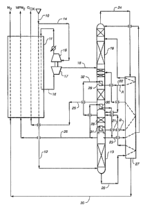
Figure 3 illustrates the general integration of an air
separation facility with a power turbine in accordance with
the present invention. As may be seen, a medium pressure
nitrogen stream may be produced from the process to be fed to
an intermediate compression stage to further improve the power
savings.
Generally, a feed stream containing at least nitrogen and
oxygen is fed through a compressor (1~) through input means
(1) and a portion thereof is then fed through conduit (11) and
conduit (26) to a cmombustion chamber. The remaining portion
of the feed stream, such as atmospheric air is fed via
-17-
conduits (12) and (1~) to cooling and purification means (15).
At this stage, the feed stream may be enhanced by using an
auxiliary compressing means (14) using a feed stream also
containing at least oxygen and nitragen, such as atmospheric
air. This auxiliary feed stream is also passed through
cooling and purification means (15).
Then, the feed stream passing through conduit (16) is fed
to the feed stream separation facility wherein a nitrogen
stream, a medium-pressure nitrogen stream (MPNz) and a gaseous
oxygen stream are produced. The nitrogen stream and medium
pressure nitrogen stream exit via conduits (21) and (22),
respectively, and a fed, respectively, through compression
stages (23) and (24) and then to conduit (25) for feeding into
combustion chamber (27). Fuel is introduced to the combustion
chamber (27) via conduit (2~). Then, hot gas from the
combustion chamber is fed via conduit (29) to gas turbine
(31), whereinafter a portion of the hot exhaust is used to
drive a power turbine (31) and the remaining portion is fed to
canduit (32) for venting. Power will be generated in
generator
Additionally, although not depicted in Figure 3, the
exhaust in conduit (32) may be utilized to generate steam for
power generation.
In more detail, a gas turbine arrangement may be used
wherein compressed feed air or compressed mixtures containing
nitrogen and oxygen are mixed with fuel and combusted. In
~~t~~~ ~3
-
essence, compressed nitrogen derived by separation in any kind
of cryogenic "cold box" is injected .into a combustion chamber
to control the pressure in the combu;~tion chamber and to
minimize the formation of nitrogen oacides (NOx).
The hot combustion mixture can also be quenched with.
nitrogen gas and the resulting gaseous mixture is then
expanded in a power turb~.ne for power recovery. Exhaust gas
,from the gas turbine is usually thera passed to a steam
generator where the residual heat is recovered for steam
production. The steam produced may be used in other sections
of the process or can be further expanded in the steam
turbines to recover the additional power.
Thus, the present invention also provides an apparatus
and process for generating steam for power generation.
The present apparatus for generating steam for power
generation, entails:
a) feed stream input means upstream of a combustion
chamber for inputting a compressed feed stream containing at
least nitrogen and oxygen to a combustion chamber,
b) a combustion chamber having fuel input means,
c) an apparatus for producing oxygen and nitrogen from a
feed stream containing at least oxygen and nitrogen, which
comprises a triple rectification column comprising a higher
pressure column having feed stream input means, heat exchange
means joining the upper end of the higher pressure column and
the lo~rer end of both a low pressure and an intex~ediate
CA 02089053 2002-12-19
- 19 -
column, separate conduit mews for feeding nitrogen-rich
liquid from the higher pressure column to the lower
pressure column and oxygen-rich liquid to the intex~mediaGe
column, separate conduit means for feCding the products of
the intermedimte column to the low pressure Golumri as
feeds, separate conduit means for discharging rtitx~ogen-r~.ch
gas from the low pressure column, separate conduit means
for c~i.scharging an oxygen-rich stream from the low pressure
column and wherein the top of the intermediate column is in
heat exchange relation with the low preaeure column at a
location above a bottom reboiler of the 1Qw pressure
column, the apparatus having at least one separate conduit
for feeding nitrogen to the combustion chamber and sepaxate
conduit means f4r gaseous oxygen product,
d? a power turbine downstream of this combustion
chamber in fluid connection therewith, and
e? ger~.exating means driven by the power turbine.
As indicated above, exhaust gas from the power tuxbine
is usually passed to the steam generator where residual
heat is recovered for steam production.
The present process for generating steam for power
generation, entails:
~~~~~~z3
-20--
a) feeding a first fraction of a feed stream containing
at least nitrogen and oxygen, and fuel to a combustion
chamber,
b) feeding a~t least the remaining portion of the feed
stream to a cryogenic apparatus wherein the feed stream is
cooled, cleaned and dried and oxygen and nitrogen separated
therefrom,
c) passing hot exhaust gas from the combustion chamber to
a gas turbine downstream of the combustion chamber and in
fluid connectian therewith, and
d) passing exhaust gas from the gas turbine to a steam
generator to recover residual heat for steam production.
Notably, in the above process, oxygen and nitrogen are
separated from the feed stream using the present cryogenic
pr~CesS. F~urtl'ler, ~n the process of generating steal, a
fraction of feed stream, such as air, going to the process is
obtained from a compressor means driven by a gas turbine.
As a fuel, while any foal may be used, it is advantageous
to use a gasification means, such as a coal gasifier, to
generate a fuel gas mixture of Ii2, CO and C~I4, for example,
which results from feeding oxygen from a cryogenic pressure at
a pressure of about 2~--35 bar to the coal gasif~.er. The
resulting fuel is fed to the combustion chamber.
The cryogenic process also furnishes nitrogen to the
combustion chamber at a pressure of about ~-2~ bar, i.e., such
as about 16 bar. Notably, in furnishing nitrogen to the
--21--
combustion chamber, the mass balance can be restated from the
depletion resulting from the ex~tract:ion of air for the
cryogenic feed stream.
Tn Figure 4, an alternative arrangement is depicted
wherein the condenser of the intermediate column is detached
from the low pressure column. Figure ~ illustrates
essentially the same process as is depicted in Figure 1,
however, the condenser of the intermediate column (28) is
detached from the low pressure column (19). This condenser is
fed by a fraction of the liquid produced at the bottom of the
intermediate column. The minor modifications shown would be
readily understood by the artisan in view of Figure 1.
Figure 5 illustrates the McCabe-Thiele diagrams for the
present three-column process and the conventional two-column
profess, clearly showing the advantageous nature of the
present process.
Thus, in accordance with the present invention both
processes and apparati therefor are provided.
For example, the apparatus depicted in Figure 1 may be
described as an apparatus for producing oxygen and nitrogen
having three distillation columns, which comprises a triple
fractionata.ng means comprising a higher pressure column having
feed stream input means, heat exchange means joining the upper
end of the higher pressure column and the lower end of both a
low pressure and axi intermediate column, separate conduit
means for feeding nitrogen-rich liquid from the higher
2~~~~~~~
pressure column to the lower pressure column and oxygen-rich
liquid to the intermediate column, separate conduit means for
feeding the products of the intermediate column to the low
pressure column as feeds, separate conduit means for
discharging nitrogen-rich gas from t;he low pressure column,
separate conduit means for discharging oxygen product from the
low pressure column, and wherein the top of the intermediate
column is in heat exchange relation with the low
pressure column at a location above a bottom reboiler of the
low pressure column.
The apparati of Figure 2 may be described similarly as
Figure 1.
The present invention also provides an apparatus for
producing oxygen and nitrogen having three distillation
columns, which entails a triple rectification column
comprising a higher pressure column having feed stream input
means, heat exchange means joining the upper end of the higher
pressure column and the lower end of both a low pressure and
an intermediate column, separate conduit means for feeding
nitrogen-rich liquid from the higher pressure column to the
lower pressure column and oxygen-rich liquid to the
,fa3te~nediate column, separate conduit means for feeding the
products of the intermediate column to the low pressure column
as feeds, separate conduit means for discharging nitrogen-rich
gas from the low pressure column, separate coa~duit means for
discharging an oxygen-rich stream from the low pressure
_2~_
column, separate conduit means for transferring liguid
produced at the bottom of the intermeadiate calumn to the
overhead of the intermediate column wind separate conduit means
far feeding resulting vaporized liquid from the overhead
candenser to the low pressure column.
The apparati of Figure 4 may also be described similarly
except that the side arm intermediate calumn is not in heat
exchange relation with, the low pressure column. Separate
conduit means is provided to feed the liquid produced at the
bottom of the intermediate column to its overhead condenser.
The respective arrangements may be readily appreciated from
Figure 4.
Having described the present invention, it will naw be
apparent to one of ordinary skill in the art that many changes
and.modifications can be made to the above--described
embodiments without departing from the spirit and the scope of
the present invention.