Note: Descriptions are shown in the official language in which they were submitted.
60691CEB5613 -1- 2 ~ 29
GEAR P~MP FO~I ~EIIGH VISCOSITY MATERIAI,
FIELD OF q~HE INVEN'rION
The invention relates generally to
transporting materials and, more particularly, to a
pump for high viscosity materials used in the
manufacture of photographic film base.
BACKGROI~ND OE' THE INVENTION
10 Apparatus for transporting or pumping
materials are well known in the art. Conventional gear
pumps are typically constructed in a manner as shown in
Fig. 1. Such pumps include a pump body 1 having an
inlet and outlet end (not shown), a pair of herringbone
gears 2 & 3, a pair of side plates 4 & 5, two internal
double roller bearings 6 mounted on each of the side
plates 4 & 5 (Fig. 2) and two gear support shafts 7 & 8
mounted for rotation in bearings 6. These pumps are
particularly well suited for pumping, for example crude
oils, and other materials having a viscosity up to
about 1.0 x 10⁵ centipoise (cps).
An earlier pump for materials having a
viscosity up to about 1.0 x 10⁵ cps is disclosed and
illustrated in U. S. Patent No. 4,859,161. The pump
uses double roller bearings mounted on rotational side
pl~tes which enables the rotation of the pump to vary
without changing the structure of the pump. Other
pumps that use some sort of gear arrangement are
disclosed in U. S. Patent Nos. 4,329,128 and 4,806,080.
In each of these prior art pumps, only low viscosity
materials can be pumped because there are no means of
reducing the pressure buildup in the pump housing, and
particularly, reducing the load on the shaft and
bearing assembly. Thus, severe premature pump and /or
component part wear would result if these pumps were
used to transport materials having viscosities very
much greater than 1.0 x 10⁵ cps.
According]y, a major shortcoming of earlier
pumps is that they are not adapted for transporting
materials having viscosities greater than about 1.0 x
60691CEsS613 -2- 2 ~ 2 ~
105 cps. Much beyond this viscosity, the integrity of
the pump components is severely compromised. The life
of gear pump bearings, for example, depends primarily
on the load on the bearing and shaft assembly,
discharge pressure, liquid viscosity, and proper
alignment of the components like shafts and bushings
and, to a lesser extent, on the speed and operating
temperature. Thus, in order to transport highly
viscous materials, e.g., cellulose acetate with a
viscosity of about 3.0 x 10⁵ cps, it is crucial that
the wear rates of the bearings and associated
components of the apparatus are minimized. Moreover,
the excessive wear of the conventional double roller
bearings used in conventional pumps leads to the wear
and misalignment of the gear assembly and wear of the
side plates that support the bearings. These component
compromises, particularly at high shaft/bearing
assembly loads caused by pumping high viscosity
materials, result in an eventual catastrophic failure
of the conventional pump.
herefore, a need exists for a pump to
transport highly viscous materials, such as cellulose
acetate, which will not be subject to the high wear
rates and severe failures of conventional pumps.
SI~MMARY ~)F THE INVENTION
It is, therefore, an object of the invention
to provide gear pumps for high viscosity materials
which overcome the shortcomings of the prior art.
Accordingly, for accomplishing these and
other objects of the invention, there is provided a
pump for transporting materials having a viscosity up
to about 3.0 x 10⁵ cps comprising a pump body formed
with a gear receiving means and having an inlet end and
a discharge end. A pair of intermeshing gears are
arranged in the gear receiving means in a manner to
form an inlet side and a discharge side, each side
being correspondingly spatially related to the inlet
and discharge ends, respectively, of the pump body. A
60691CEB5613 -3~ 2~
pair of side plates having bearing receiving means are
mountable to the pump body. A pair of plain bearing
means is press fitted in the bearing receiving means.
Moreover, means are formed in the side plates for
relieving pressure build-up in the intermesh of gears
as material is transported towards the discharge end of
the pump body thereby reducing the load on the
shaft/bearing assembly and, hence, extending the
service life of the assembly.
Accordingly, an important advantage of the
apparatus is that highly viscous materials, such as
cellulose acetate having a viscosity of 3.0 x 10⁵ cps,
can be transported without jeopardizing the integrity
of the pump.
BRIEF DESCRIPTION OF THE DRAWINGS
The foregoing as well as other objects,
features and advantages of this invention will become
more apparent from the following detailed description
when taken in conjunction with the appended figures in
which
; Figures l and 2 illustrate a conventional
gear pump, wherein Figure 1 is a side view of the prior
art pump and Figure 2 is a fragmented section view
along the 2-2 line of Figure 1;
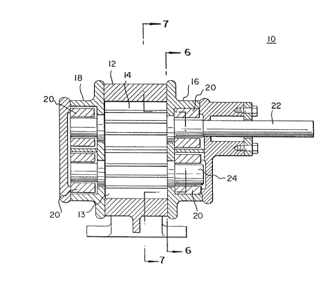
Figure 3 is a side view of the pump of the
invention;
Figure 4 is a section view along the 4-4 line
of Fig. 5;
Figure 5 is an elevation end view of the
bearing and shaft assembly;
Figure 6 is a partial section view along the
6-6 line of Figure 3 w'nerein the shafts are omitted and
the bearings moved into the plane of view for purposes
of illustration; and,
Figure 7 is a section view along the 7-7 line
of Figure 3.
60691CEB5613 -4- 2 ~ ~ 9 ~ 2 ~
DETAILED DES~RIPTION OF T~IE INVE~TIO~
Turning now to the drawings and more
particularly to Figure 3, there is shown a pump for
materials having a viscosity up to about 3.0 x 10⁵ cps,
such as cellulose acetate, in accordance with the
principles of the invention. The pump, generally
designated 10, comprises a pump body 12 having a gear
receiving cavity 13 and an inlet end and a discharge
end (not shown). Gear receiving cavity 13 has arranged
therein a pair of intermeshing gears 14 between the
inlet end and the discharge end of pump body 12 (Fig.
7). Intermeshing gears 14 form an inlet side 15 and a
discharge side 17, each corresponding to the inlet and
discharge ends, respectively, of pump body 12 (Fig. 7).
A pair of similar right and left handed side plates
16,18 each having cavities 21 (Fig. 6) for receiving a
pair of plain bearings 20 is mounted to either end of
pump body 12 to close the gear receiving cavity 13.
Plain bearings 20 in each side plate 16,18 support a
driven gear shaft 22 and a driving shaft 24.
The preferred bearings 20, shown in Figures 4
and 5, are a cylindrically shaped, chemically inert,
wear resistant plain ceramic bearing. The plain
ceramic bearings provide ease of assembly of the pump
10 and are easier to clean than conventional steel
bearings and, thus, can be reused. Moreover, the
ceramic bearings are more wear resistant than steel
used in conventional pumps. In the preferred
embodiment, the ceramic material is sintered silicon
carbide. However, other ceramics may be used such as
silicon nitride, aluminum oxide, or zirconia. The
interior wall 32 of bearings 20 (Fig. S) forms a high
stress zone 26 (denoted by shaded portion) and a low
stress zone 28 (denoted by crosshatched portion) due to
deflection caused by pressure in the gear intermesh 14.
; Maximum pressure is exerted on the interior wall 32 in
the high stress zone 26 as highly viscous materials are
transported by intermeshing gears 14 to the discharge
end of pump body 14. Conversely, minimum pressure is
6o69lcEs56l3 -5- 2 ~ 2~
exerted on the interior wall 32 in the low stress zone
28. Interior wall 32, moreover, has a groove or
channel 30 or a plurality of spaced apart grooves or
channels 30 along the wall length in the low stress
zone 28 to provide a means for the working materials to
enter inside bearings 20 so that a continuous
hydrodynamic film is formed to lubricate bearings 20.
Channels 30 also relieve particles from gear shafts
22,24. In the preferred embodiment, interior wall 32
has two symmetrically arranged channels 30 spaced 45
on either side of a centerline 31 drawn through both
shafts 22,24 and diagonally opposite a portion of the
high stress zone 26. Those skilled in the art would
appreciate that one or more channels 30 can be arranged
in other spaced relationships in the low stress zone 28
of bearings 20 with the same or similar effect. In
operation, when high viscosity working material
squeezes through intermeshing gears 14 (Fig. 7), the
working materials exert an upward force on the
intermeshing gears 14 which correspondingly exerts a
force on the shafts 22,24 and bearings 20 in the high
stress zone 26. This results in premature wear of
shafts 22,24 and bearings 20 in prior art pumps.
Channels 30, positioned in the low stress zone 28,
provide additional working materials to high stress
zone 26 as the materials are transported and act as a
means of lubricating bearings 20 and shafts 22,24
thereby providing additional protection from premature
wear. Also, a clearance 38 is formed between shafts
22,24 and bearings 20 by the working materials, i.e.,
the materials being pumped, in the high stress zone 26
and low stress zone 28 of bearings 20 as described
hereinbelow.
Plain bearings 20 are press fitted in bearing
receiving cavity 21 of side plates 16,18. Round metal
pins 34 (shown in Figs. 6 & 7) lock bearings 20 against
rotation in the bearing receiving cavity 22 via pin
receiving slot 36 (Fig. 5). Those skilled in the art
will appreciate any suitable means of securing bearings
60691CEB5613 -6- 2 ~ 2~
20 may be used, such as epoxy bonding, brazing, etc..
Construction of bearings 20 is such that the clearance
38 (Fig. 5 & 7) between shafts 22,24 supported in
bearings 20 and bearings 20 is in the range from about
.001 inches to about .010 inches during the operation
of gear pump 10. A clearance between the shafts 22,24
and bearings 20 of .005 inches is preferred so that
there is n~ contact between the shafts 22,24 and
bearings 20 during operations. Moreover, the clearance
40 between the bearing receiving cavity 21 and the
outside diameter of bearings 20 must be minimum,
preferably in the range of .001 and .005 inches (Fig.
6). In accordance with the preferred embodiment of the
invention, a clearance of .002 inches is preferred.
Experiments indicate that a clearance in the above
range minimizes undue radial movement of the bearings
20 during operations.
Furthermore, the service life of gear pump 10
is extended by wear resistant shafts 22,24 which rotate
inside the ceramic plain bearings 20. Shafts 22,24 are
rendered more wear resistant by applying hard coatings.
Any known technique of hardening a surface may be
employed, such as thermal spraying. Thermally sprayed
tungsten carbide is the preferred hard coating
technique. Hard coating shafts 22,24 also enables
shafts 22,24 to be reused after applying new coatings.
;~ Further, shafts 22,24 are lubricated by pumped
materials, as indicated above. Distortions in both
shafts 22,24 and bearings 20 must be limited such that
; 30 shafts 22,24 do not touch their respective bearings 20
at any point during operation. This is ensured by
keeping the individual runout of shaft 22,24 and the
bearings 20 to a minimum. Runout is measured by using
any conventional means such as a dial indicator or
feeler gage. The runout of bearings 20 surfaces on
shaft 22,24 is in the range of .0001 inches to about
.0005 inches. Good resulks have been obtained with a
runout less than about .0005 inches. The cylindricity
and runout of the inside diameter and outside diameter
60691CEB5613 -7~ 2 ~
of bearings 20 are kept within 0.0001 inches to about
.0005 inches.
Eigure 6 shows one of the side plates 16,18
constructed using either a hardened steel or steel
coated with a wear resistant coating. The preferred
wear resistant coating is a thermally sprayed tungsten
carbide. Other coatings may be used, for example,
thermally sprayed chrome oxide, aluminum oxide or
titanium carbide. The surface d6 of side plates 16,18
is also coated with a hard coating such as tungsten
carbide to increase the wear resistance. Surface 46 of
side plates 16,18 also serves as a wear plate, thereby
eliminating the need for a separate wear plate.
In the preferred embodiment of the invention,
means for relieving pressure buildup in the intermesh
of gears 14, i.e., the discharge side of centerline 31,
are provided (Figs. 6 ~ 7). A recess portion 50 having
a substantially flat base (not shown) in side plates
16,18 is the preferred means of relieving pressure
build-up in the intermesh of gears 14. Recess portion
50 may have any suitable size and shape within the
general requirements of the invention, such as,
circular, triangular, square, etc. Experiments
conducted by inventors indicate that a substantially
bell shaped recess portion 50 which extends from near
the centerline 31 on the discharge side 17 of the
intermesh of gears 14 beyond the point wherein the
gears 14 are separated, i.e., beyond the point where
there is no trapped working material (shown clearly in
Fig. 7) is preferred and the most convenient to
machine. Moreover, recess portion 50 has a depth in
the range .060 inches to about .250 inches. The
preferred depth of recess portion 50 is .125 inches.
Recess portion 50 provides for reduction of the
excessive pressure build-up in the intermesh of gears
14 on the discharge side as material is being pumped
(direction denoted by arrows in Fig. 7) towards the
discharge end of pump body 12 (Fig. 7). Thus, recess
portion 50 diverts the material flow towards the
60691CEB5613 -8-
discharge end of pump body 12 thereby resulting in
reduced load on bearings 20 which helps maintain the
running clearance between shafts 22,24 and the bearings
~0. Secondarily, increased pressure at the discharge
end of pump body 12 results from the diversion oE
pressure buildup in the intermesh of gears 14 toward
the discharge end ~7 of pump body 12.
The invention has thus been described in
detail with particular reference to preferred
embodiments thereof, but it will be understood that
variations and modifications can be effected within the
spirit and scope of the invention as described
hereinabove and as defined in the appended claims.