Note: Descriptions are shown in the official language in which they were submitted.
~0892~8
PATENT APPLICATION
Attorney Docket No. D/92214
APPARATUS AND METHOD
OF IMAGE REGISTRATION
This invention relates generally to an apparatus and method for
positional tracking a moving photoconductive belt, and more particularly
concerns
aligning an imager in an electrophotographic printing machine to permit
superposing registered latent images to be exposed on the belt so that the
images
are aligned in the process and lateral directions, and skew position.
In single pass electrophotographic printers having more than one process
station which provide sequential images to form a composite image, critical
control
of the registration of each of the sequenced images is required. This is also
true in
multiple pass color printers, which produce sequential developed images
superimposed on to form a multi-color image. Failure to achieve registration
of the
images yields printed copies in which the images are misaligned. This
condition is
generally obvious upon viewing of the copy, as such copies usually exhibit
fuzzy
color separations, bleeding and/or other errors which make such copies
unsuitable
for intended uses.
A simple, relatively inexpensive, and accurate approach to register latent
images superposed in such printing systems has been a goal in the design,
manufacture and use of electrophotographic printers. This need has been
particularly recognized in the color and highlight color portion of
electrophotography. The need to provide accurate and inexpensive registration
has
become more acute, as the demand for high quality, relatively inexpensive
color
images has increased.
Various techniques for registering images on belts have hereinbefore
been devised as illustrated by the following disclosures, which may be
relevant to
certain aspects of the present invention
US-A-4,912,491
Patentee: Hoshino et ai.
Issued : March z7, 1990
2U89218
US-A-RE.32,967
Patentee: St. John et al.
Issued: June 27, 1989
Japanese Patent No. 55-98016
Patentee: Honda
Issued: July 25, 1980
US-A-4,135,664
Patentee: Resh
Issued: January 23, 1979
US-A-4,963,899
Patentee: Resch, III
Issued: October 16, 1990
GDR-A-239,390
Patentee: Schmeer et al.
Issued: September 24, 1986
US-A-4, 569, 584
Patentee: St. John et al.
Issued: February 11, 1986
US-A-4,961,089
Patentee: Jamzadeh
Issued : October 2, 1990
The disclosures of these references are briefly summarized as follows:
US-A-4,912,491 discloses an apparatus for forming superimposed images
and registration marks corresponding to the position of the images associated
therewith. The registration marks are formed apart from the imaging portion of
the
medium ~n a transparent area to be illuminated from the backside. Detectors
sense
the position of the registration marks as the marks pass between the
illuminated
areas. The sensing of the registration marks is used in determining proper
_2-
X089218
registration positioning, whereby the image forming devices may be adjusted to
achieve such registration.
US-A-RE.32,967 discloses a web tracking system for a continuous web
which passes along a predetermined path through one or more processing
stations.
The tracking system has aligned tracking indicia on one or both sides of the
web and
detectors sensing these indicia which are indicative of dimensional changes in
width
and length of the web at a particular point. An edge sensor is also provided
to
determine movement of the web.
Japanese Patent No. 55-981016 discloses compensating for errors in the
process direction of movement of the belt by rotation of shafts which engage
the
tension and drive rollers of the belt. Upon detection of movement of the belt
in a
non-linear fashion (e.g., the edge exhibiting a zigzag effect), pressure is
applied on
these shafts to tension the belt through rollers to urge the belt to turn and
maintain
its desired orientation.
US-A-4,135,664 control, lateral registration in printers. A cylinder drum
print is marked at a first print station with ink of a first color. The marks
are scanned
and a positional count is summed until the marks of a record station are
detected.
By detection and averaging of the time differential between the lateral
registration
marks, lateral errors can be determined and corrected by physically shifting
the
lateral position of the print cylinder.
US-A-4,963,899 discloses an electrostatographic printing and copying
device employing a registration system which senses discharge line patterns to
provide both in-track and cross-track signal information permitting
synchronous
processing to provide accurate multi-color image reproduction.
GDR-A-239,390 discloses a device having a first and second set of
proximity sensors which operator to signal a first off-center condition. If
the
permissible lateral off-center condition is exceeded, a second proximity
sensor shuts
down the device.
US-A-4,569,584 discloses a color electrographic recording apparatus
having a single imaging station through which the recording medium is passed
in a
first and second direction. After each latent image is formed, it is developed
and the
medium is returned to superpose another image thereon. Aligned tracking lines
and
registration lines are sensed to permit corrections of lateral and process
direction
errors.
US-A-4,961,089 discloses an electrostatic reproduction apparatus having a
web tracking system wherein the web rotates on rollers through image
processing
-3-
20892 18
stations. A guide is provided to move the web around the rollers. The guide
includes a steering roller which is actuated by a web tracking system.
An aspect of the invention is as follows:
A print device having an imageable surface adapted to move along a
preselected path, wherein the improvement includes:
a first image processing station adapted to record a first latent image
and a target latent image on the imageable surface;
means for developing at least the target latent image on the imageable
surface to form a developed target im age;
a second image processing station adapted to record a second latent
image on the imageable surface; said second image processing station
illuminating the developed target image to form an illuminated image;
means for sensing an intensity level of the illuminated image;
means for correlating said intensity level sensed to predefined
deviations of the imageable surface from the preselected path; and
means, responsive to said correlating means, for adjusting said image
processing station to compensate for deviations of the imageable surface from
the preselected path.
Other features of the present invention will become apparent as the
following description proceeds and upon reference to the drawings, in which:
Figure 1a and 1b is a top and a side view of an imaging station for
carrying out and taking advantage of the various aspects of the present
invention and;
Figure 2 illustrates a Gaussian array line pattern on the
photoconductive belt and the corresponding Gaussian pattern for the image
bar.
_4_
,.
r
Y._..-xu
20892 18
Figure 3 is a signal representation of a simple pixel pattern to measure
lateral registration;
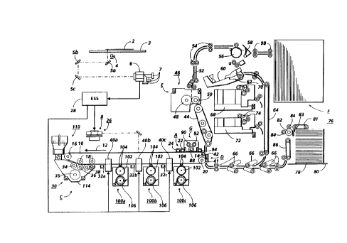
Figure 4 is a schematic elevational view depicting an illustrative
electrophotographic printing machine incorporating the features of the present
invention therein.
While the present invention will be described in connection with a
preferred embodiment thereof, it will be understood that it is not intended to
limit
the invention to that embodiment. On the contrary, it is is intended to cover
all
alternatives, modifications and equivalents that may be included within the
spirit
and scope of the invention as defined by the appended claims.
DETAILED DESCRIPTION OF THE INVENTION
For a general understanding of the features of the present invention,
reference numerals have been used throughout to designate identical elements.
Figure 4 schematically depicts the various elements of an illustrative color
electrophotographic printing machine incorporating the method of the present
invention therein. It will become evident from the following discussion that
this
method is equally well suited for use in a wide variety of printing machines
and is
not necessarily limited in its application to the particular embodiments
depicted
herein.
Inasmuch as the art of electrophotographic printing is well know, the
various processing stations employed in the Figure 4 printing machine will be
shown
hereinafter schematically and their operation described briefly with reference
thereto.
With reference to Figure 4, the color copy process typically involves a
computer generated color image which may be inputted into image processor unit
(not shown), or alternately a color document 2 to be copied may be placed on
the
surface of a transparent platen 3. A scanning assembly having a halogen or
tungsten lamp 4 is used as a light source to illuminate the color document 2.
The
light reflected from the color document 2 is reflected by mirrors 5a, 5b and
Sc,
through lenses (not shown) and a dichroic prism 6 to three charged-coupled
devices
(CCDs) 7 where the information is read. The reflected light is separated into
the
three primary colors by the dichroic prism 6 and the CCDs 7. Each CCD 7
outputs an
analog voltage which is proportional to the strength of the incident light.
The
analog signal from each CCD 7 is converted into an 8-bit digital signal for
each pixel
(picture element) by an analog~digitai converter. The digital signal enters an
image
-S-
..
2089218
processor unit. The output voltage from each pixel of the CCD 7 is stored as a
digital
signal in the image processing unit. The digital signal which represent the
blue,
green, and red density signals is converted in the image processing unit into
four
bitmaps: yellow (Y), cyan (C), magenta (M), and black (Bk). The bitmap
represents
the exposure value for each pixel, the color components as well as the color
separation.
The electrophotographic printing machine employs a semi-transparent
photoconductive belt 10. Preferably, photoconductive belt 10 is made from a
photoconductive material coated on a ground layer, Which, in turn, is coated
on
anti-curl backing layer. The photoconductive material is made from a transport
layer
coated on a generator layer. The transport layer transports positive charges
from
the generator layer. The interface layer is coated on the ground layer. The
transport
layer contains small molecules of di-m-tolydiphenydiphenylbithenyldiamine
dispersed in a polycarbonate. The generation layer is made from trigonal
selenium.
The grounding layer is made from a titanium coated mylar. The ground layer is
very
thin and allows a portion of the incident light to pass therethrough. Other
suitable
photoconductive materials, ground layers, and anti-curt backing layers may
also be
employed. Belt 10 moves in the direction of arrow 12 to advance successive
portions
of the photoconductive surface sequentially through the various processing
stations
disposed about the path of movement thereof. Belt 10 is entrained about
stripping
roller 14, tensioning roller 16, idler rollers 18, and drive roller 20.
Stripping roller 14
and idler rollers 18 are mounted rotatably so as to rotate with belt 10.
Tensioning
roller 16 is resiliently urged against belt 10 to maintain belt 10 under the
desired
tension. Drive roller 20 is rotated by a motor coupled thereto by suitable
means such
as a belt drive. As roller 20 rotates, it advances belt 10 in the direction of
arrow 12.
Initially, a portion of the photoconductive surface passes through
charging station A. At charging station A, two corona generating devices,
indicated
generally by the reference numerals 22 and 24, charge photoconductive belt 10
to a
relatively high, substantially uniform potential. Corona generating device 22
places
all the required charge on photoconductive belt 10. Corona generating device
24
acts as leveling device, and fills in any areas missed by corona generating
device 22.
Next, the charged portion of the photoconductive surface is advanced
through imaging station B. At imaging station B, the uniformly charged
photoconductive surface is exposed by an imager, such as a laser based output
scanning device 26, which causes the charged portion of the photoconductive
surface to be discharged in accordance with the output from the scanning
device.
-6-
2a8~~I8
The scanning device is a laser raster output scanner (ROS). The ROS performs
the
function of creating the output image copy on the photoconductive surface. it
creates the image in a series of horizontal scan lines with each line having a
certain
number of pixels per inch. The ROS may include a laser with rotating polygon
mirror
blocks and a suitable modulator or, in lieu thereof, a light emitting diode
array (LED)
as a write bar. An electronic subsystem (ESS) 28 is the control electronics
which
prepare and manage the image data flow between the imaging processing unit and
the ROS. It may also include a display, user interface, and electronic
storage, i.e.
memory, functions. The ESS is actually a self-contained, dedicated mini
computer.
The photoconductive surface, which is initially charged to a high charge
potential, is
selectively discharged by the ROS recording a charged pattern corresponding to
the
information desired to be printed on the photoconductive surface. In addition
to
this charge pattern, the ROS writes target marks or indicia on photoconductive
belt
10. Preferably, the target marks are proceeding and /or adjacent to the frame
of the
image charge pattern.
At development station C, a magnetic brush development system,
indicated generally by the reference numeral 30 advances developer material
into
contact with the electrostatic latent image. The development system typically
comprises a plurality of three magnetic brush developer rollers, indicated
generally
by the reference numerals 34, 36 and 38. A paddle wheel 35 picks up developer
material from developer sump 114 and delivers it to the developer rollers.
When
developer material reaches rolls 34 and 36, it is magnetically split between
the rolls
with half of the developer material being delivered to each roll.
Photoconductive
belt 10 is partially wrapped about rolls 34 and 36 to form extended
development
zones. A magnetic roller, positioned after developer roll 38, in the direction
of
arrow 12, is a carrier granular removal device adapted to remove any carrier
granules adhering to belt 10. Thus, rolls 34, 36, and 38 advance developer
material
into contact with the electrostatic latent image and the latent target marks.
The
latent image and the latent target marks attract toner particles from the
carrier
granules of the developer material to form a developed toner powder image on
the
photoconductive surface of belt 10. Toner dispenser 110 dispenses unused toner
particles into sump 114. Each of the foregoing developer rollers include a
rotating
sleeve having a stationary magnetic disposed interiorly thereof. The magnetic
field
generated by the magnet attracts developer material from paddle wheel 35 to
the
sleeve of the developer roller. As the sleeve rotates, it advances the
developer
material into the development zone where toner particles are attracted from
the
_7_
2089218
carrier granules to the charged area latent image and the latent target marks.
In this
way, the charged area latent image and the latent target marks are developed
with
toner. The toner particles being employed in developer unit 30 are black. The
black
developed latent image and developed latent target marks continues to advance
with photoconductive belt 10 in the direction of arrow 12.
Corona generator 32a recharges the photoconductive surface of belt 10.
A second imaging station 40a, which is representative of imaging stations 40b
and
40c, is shown in greater detail in Figures 1a and 1b. Now turning to Figures
1a and
1 b, the second imaging station 40a includes a LED image array bar 136, or may
for
example include gas discharge image bar, LCD shutter image bar or another ROS.
The imaging station 40a is used to measure the registration of the
photoconductive
belt, and to superimpose a subsequent image by selectively discharging the
recharged photoconductive surface. Specifically, imaging stations 40a, 40b and
40c
have an inner housing 120 which is mounted on support frame 122 and contains a
sensor unit 124. An outer housing 130 has the image bar 136 secured therein
facing
the senor unit 124 in the inner housing. The sensor unit 124 is light
sensitive device,
such as a PIN type photodiode or photomultiplier tube. The sensor unit 124 is
sensitive to the wavelength used by its corresponding imager. No optics or
focusing
is necessary for the sensor unit, however, it is preferred to use a focusing
lens (not
shown) to enable a higher signal to noise ratio with any given sensor unit by
allowing the sensor unit to measure more of the imager pixels. The
photoconductive belt 10 is disposed between the inner housing 120 and the
outer
housing 130. The spacing between the imager 136 and the sensor unit 124 is
equal
to the nominal focal length between the imager and the photoconductive belt
10,
plus the small distance the sensor unit is placed behind the photoconductive
belt 10,
(typically 1 through 5 mm). The image bar 136 is mounted on the outer housing
by a
slide mount arrangement 137 which allows translation of the image bar in a
plane
substantially parallel to the belt. Further, the outer housing 130 is
pivotally
connected to permit angular translation m the place of the belt.
Stepper motor 138 is mounted on the outer housing 130 in a suitable
fashion. Actuation of the stepper motor 138 selectively translates the image
bar 136
in a forward and reverse manner in the slide mount 137. Thus, actuation of the
stepper motor 138 drives the image bar 136 in a linear fashion with respect to
the
inner housing 120 and belt 10. It will be appreciated that stops (not shown)
may be
provided in the outer housing to limit the travel of the image bar 136
relative to the
inner housing 120. Stepper motor 139 is mounted on frame 122 and actuation of
the
_g_
20892 18
stepper motor 139 causes the outer housing 130 to rotate and, consequently,
image
array bar 136 rotates. In this embodiment, stepper motors 138 and 139 have
relatively small incremental step actuations utilizing gear reduction units
(not
shown) incremented approximately in .001 mm divisions which is a fraction of a
pixel
width. Image bars 136 can be linearly actuated and, further, can be rotational
actuated to change the orientation of image bars 136 at each of the imaging
stations 40a, 40b and 40c relative to the photoconductive belt 10. The stepper
motors 138 and 139 in each of the imaging stations 40a, 40b and 40c, are
actuated by
control signals from the ESS 28. Further, other means can be used to translate
and
rotate image bars 136. Included could be electronic means whereby the
translation
can be accomplished by shifting pixels and or image lateral timing in
combination
with the electronic means for rotating imager output.
In this instance, misregistration of the superposed images in the process
direction will be avoided when the video image signal output from ESS 28 to
each of
the imaging station is appropriately timed to compensate for the belt travel
between stations. That is, for example, registration in the process direction
begins
when the second imager station 40a scans for the presence of a target mark
which
was exposed and developed by the first imager 26 and developer unit 30. The
arrival
of the target marks at the second imaging station 40a, and subsequent imaging
stations are detected by turning the imager on to a level such that the light
can be
detected by sensor unit 124 through the semi-transparent photoconductive
surface
of belt 10 for a window of time when the timing mark is expected. In some
situations where the imager exposure intensity is varied by varying the image
on
time, it is preferred to turn the image light on for the entire pixel cycle so
as to _
provide a uniform temporal signal to sensor 124. In the present embodiment,
the
light level used is the same light used to expose the charged belt 10 which is
approximately S ergs/cm2. However, it should be apparent to one skilled in the
art
that the level would depend on the transmittance of photoconductive beat and
the
sensitivity of sensor unit 124. The measurement by the sensor unit 124 of the
occlusion of the light from the second imaging station 40a provides the timing
signal. Additionally, the process direction registration sensing signals could
be used
to trigger the second (and subsequent) image bars at the appropriate time to \
achieve line by line registration in the process direction independent of the
photoconductive belt 10 speed variation and system mechanical tolerances
Since, the light level from a single pixel of the imager may be fairly low
there is a signal to noise ratio problem with detecting the occlusion of a
single pixel
_g_
2~~~2~5
of the imager, therefore it is preferred to turn on multiple imager pixels to
improve
the signal to noise ratio, thus enhancing the detection of the target. The
number of
pixels which can be turned on is dependent on the physical width of the sensor
unit
124. For example, the sensor active area width might be 3 mm and be able to
measure approximately 47 pixels from a 400 spot per inch imager.
Also, due to intensity differences in the output of the image bars
between setup cycles caused by variations in the electrographic printing
machine, it
is preferred to monitor the intensity of the image bar 136 output with the
sensor
unit 124. The output signal from the sensor unit 124 is sent to the electronic
subsystem (ESS) 28 and a feedback signal from the electronic subsystem (ESS)
28 is
sent to the imaging station to compensate for any intensity variations.
Misregistration in the lateral direction can be avoided by using a target
pattern consisting of a developed array of lines perpendicular to the image
bar axis
and then illuminating (utilizing an appropriate illumination pattern) this
developed
line array with the subsequent image bars. Lateral registration is then
achieved by
scanning the illumination pattern along the axis of the imager and determining
the
position of the maximum or minimum light signal. The choice of the maximum or
minimum depends on the choice of line array pattern and illumination pattern.
A
large number of choices is possible for the initial line array pattern. For
example, the
most straight forward pattern would be repeating sequence of on off pixel
lines
parallel to the process direction (e.g. 010101010101010) with the
corresponding
pixels illuminated at the imager. Such a pattern would enable lateral
alignment to a
high precision with the highest signal to noise ratio. However, the signal to
noise
ratio would be poor in determining the lateral registration modulo pixel.
Other
patterns such as one on three off (e.g. 1000100010001), would reduce the
integral
lateral position uncertainty but at a slight loss in signal to noise ratio as
shown in
Figure 2. An example of a pattern which gives fairly good lateral position
dependence with no integral uncertainty is a gaussion like pattern such as
111011010110111.
When one of the patterns are developed, a series of lines in the process
direction will be generated, as shown in Figure 2. As this pattern passes
beneath a
subsequent image bar, which has its pixels illuminated in the same pattern,
also
shown in Figure 2, a signal can be detected through the photoconductive
surface for
the pixels that illuminate the undeveloped spaces between the lines and/or
outside
the developed area. By mechanically moving the image bar 136 with the stepping
motors 138 and 139 for displacements of less than one pixel separation and
-10-
20892 18
electronically changing the illumination pattern for integer pixel separation
displacements, it is possible to locate the position of the maximum signal
thus
aligning the image bars. Similarly, by illuminating with the same pattern on
the
image bar 136, as the developed pattern aligned can be achieved by seeking the
minimum signal. Figure 3 shows an example of the signal resulting from
misregistrations of the gaussian pattern. Adding lines to the pattern
(starting with 4
and increasing) will increase the signal to noise ratio, but not the signal
shape, as
shown in Figure 3. A minimum always occurs when the single illuminated pixel
is
aligned with the single pixel wide toner line at the center. One could also
perform
the alignment by shifting the position of the developed image on the
photoconductor rather than mechanically shifting 136 image bar. One could also
perform an approximate alignment by electrically shifting the pixels on imager
136.
It should be apparent to one skilled in the art that other patterns can also
be used to achieve alignment. The final implementation of a pattern will
depend on
various factors such as detector sensitivity, toner usage, registration
requirements
and etc.
Skew measurement and adjustment can also be achieved by the disclosed
invention. Two or more sensors are utilized in position at the inboard and
outboard
position of the photoconductive belt 10 width. Two perpendicular timing marks
are
written and developed on the same "line" by the first imaging station and the
arrival of each mark sensed at the following imaging station. Any variation in
arrival
time between the inboard and outboard marks will be sensed by the subsequent
imaging station this will indicate a skew position condition. The skew
condition can
be corrected mechanically by the stepper motor 139 rotating the outer housing
130
or electronically by changing the arrangement of the pixels in image bar to
account
for the skew or a utilization of a combination of both methods.
One advantageous feature of the present invention is that no permanent
marks are used. This eliminates the need to use a fixed pitch in the belt to
accommodate different image sizes. However, it should be apparent to one
skilled in
the art that the developed target marks could be replaced by permanent
physical
marks (i.e. holes or marked targets) to register the images on the belt. Even
though,
the use of permanent marks may decrease the total imageable surface area which
may be needed to circumvent unanticipated scratches or other physical defects
on
the ~mageable surface of the belt.
After imaging station 40a registers the image, the imaging station
superimposes a second image on the first image and the subsequent image is
-11-
.~
2089218
developed by developer unit 100a. Developer unit 100a which is representative
of
the operation of development stations 100b and 100c, includes a donor roll
102,
electrode wires 104 and a magnetic roll 106. The donor roll 102 can be rotated
either in the (with) or (against) direction relative to the motion of belt 10.
Electrode
wires 104 are located in the development zone defined as the space between
photoconductive belt 10 and donor roll 102. The electrode wires 104 include
one or
more thin Metal, Tungsten or Stainless Steel, or other suitable wires which
are
lightly positioned against donor roll 102. The distance between wires 104 and
donor
roll 102 is approximately the thickness of the toner layer on donor roll 102.
An
electrical bias is applied to the electrode wires by a voltage source. A
voltage source
electrically biases the electrode wires with both a DC potential and an AC
potential.
A DC voltage source establishes an electrostatic field between photoconductive
belt
and donor roll 102. In operation, magnetic roll 106 advances developer
material
comprising carrier granules and toner particles into a loading zone adjacent
donor
roll 102. The electrical bias between donor roll 102 and magnetic roll 106
causes the
toner particles to be attracted from the carrier granules to donor roll 102.
Donor roll
102 advances the toner particles to the development zone. The electrical bias
on
electrode wires 104 detaches the toner particles on donor roll 102 and forms a
toner
powder cloud in the development zone. The discharged latent image attracts the
detached toner particles to form a toner powder image thereon. The toner
particles
in developer unit 100a are of a color magenta. Belt 10 is recharged by the
charging
unit 32b and advances to the next imaging station 40b where the imaging
station
40b re-registers the photoconductive belt 10 and then superimposes a
subsequent
image by selectively discharging the recharged photoconductive surface and
developer unit 100b develops the image with yellow toner. The belt 10 is
recharged
by charging unit 32c and imaging station 40c re-registers the photoconductive
belt
10 and superimposes a subsequent image by selectively discharging the
recharged
photoconductive surface and developer unit 100c develops the image with cyan
toner.
The resultant image, a multi-color image by virtue of the developing
station 30, 100a, 100b and 100c having black, yellow, magenta, and cyan, toner
disposed therein advances to transfer station D. It should be evident to one
skilled in
the art that the color of toner at each development station could be in a
different
arrangement. At transfer station D, a sheet or document is moved into contact
with
the toner powder image. Next, a corona generating device 41 charges the sheet
to
the proper magnitude and polarity as the sheet is passed through
photoconductive
-12-
2089218
belt 10. The toner powder image is attracted from photoconductive belt 10 to
the
sheet. After transfer, a corona generator 42 charges the sheet to the opposite
polarity to detack the sheet from belt 10. Conveyor 44 advances the sheet to
fusing
station E.
Fusing station E includes a fuser assembly indicated generally by the
reference numeral 46, which permanently affixes the transferred toner powder
image to the sheet. Preferably, fuser assembly 46 includes a heated fuser roll
48 and
a pressure roll 50 with the powder image on the sheet contacting fuser roll
48. The
pressure roll is cammed against the fuser roll to provide the necessary
pressure to fix
the toner powder image to the copy sheet. The fuser roll is internally heated
by a
quartz lamp. Release agent, stored in a reservoir, is pumped to a metering
roll. A
trim blade trims off the excess release agent. The release agent transfers to
a donor
roll and then to the fuser roll.
After fusing, the sheets are fed through a decurler 52. Decurler 52 bends
the sheet in a first direction and puts a known curl in the sheet, and then
bends it in
the opposite direction to remove that curl.
Forwarding rollers 54 than advance the sheet to duplex turn roll 56.
Duplex solenoid gate 58 guides the sheet to the finishing station F or to
duplex tray
60. At finishing station F, sheets are stacked in a compiler to form sets of
cut sheet.
The sheets of each set are optionally stapled to one another. The set of
sheets are
then delivered to a stacking tray. In a stacking tray, each set of sheets may
be offset
from an adjacent set of sheets.
With continued reference to the figure, duplex solenoid gate 58 directs
the sheet into duplex tray 60. Duplex tray 60 provides an intermediate or
buffer _
storage for those sheets that have been printed on one side on which an image
will
be subsequently printed on the second, opposed side thereof, i.e. the sheets
being
duplexed. The sheets are stacked in duplex tray 60 face down on top of one
another
in the order in which they are being printed.
In order to complete duplex printing, the simplex sheets in tray 60 are fed,
in seriatim, by bottom feeder 62 from tray 60 back to transfer station D via a
conveyor 64 and rollers 66 for transfer of the toner powder image to the
opposed
side of the sheet. Inasmuch as successive sheets are fed from duplex tray 60,
the
proper or clean side of the sheet is positioned in contact with belt 10 at
transfer
station D so that the toner powder image is transferred thereto. The duplex
sheet is
then fed through the same path as the simplex sheet to be advanced to
finishing
station F.
-13-
~s
~a89218
Sheets are fed to transfer station D from secondary tray 68. Secondary
tray 68 includes an elevator driven by a bi-directional AC motor. Its
controller has
the ability to drive the tray up or down. When the tray is in the down
position,
stacks of sheets are loaded thereon or unload therefrom. In the up position,
successive sheets may be fed therefrom by sheet feeder 70. Sheet feeder 70 is
a
friction retard feeder utilizing a feed belt and take-away rolls to advance
successive
sheets to transport 64 which advances the sheets to rolls 66 and then to
transfer
station D.
Sheets may also be fed to transfer station D from the auxiliary tray 72.
Auxiliary tray 72 includes an elevator driven by bi-directional AC motor. Its
controller has the ability to drive the tray up or down. When the tray is in
the down
position, stacks of sheets are loaded thereon or unloaded therefrom. In the up
position, successive sheets may be fed therefrom by sheet feeder 74. Sheet
feeder 74
is a friction retard feeder utilizing a feed belt and take-away rolls to
advance
successive sheets to transport 64 which advances the sheets to rolls 66 and to
transfer
station D.
Secondary tray 68 and auxiliary tray 72 are secondary sources of sheets. A
high capacity feeder indicated generally by the reference numeral 76, is the
primary
source of sheets. High capacity feeder 76 includes a tray 78 supported on
elevator
80. The elevator is driven by a bi-directional AC motor to move the tray up or
down.
In the up position, the sheets are advanced from the tray to transfer station
D. A
fluffer and air knife directs air onto the stack of sheets on tray 78 to
separate the
uppermost sheet from the stack of sheets. A vacuum pulls the uppermost sheet
against the belt 81. Feed belt 81 feeds successive uppermost sheets from the
stack to
a take-away drive roll 82 and idler rolls 84. The drive rolls and modular
rolls guide
the sheet onto transport 86. Transport 86 advances the sheet to roll 66 which,
in
turn, move the sheet to transfer station D.
After the sheet is separated from photoconductive belt 10, some residual
toner particles in the image frame remain adhering thereto and the developed
target marks. After transfer, photoconductive belt 10 passes beneath corona
generating device 94 which charges the residual toner particles to the proper
polarity. Thereafter, the pre-charged array lamp (not shown), located inside
photoconductive belt 10 discharges the photoconductive belt in preparation for
the
next imaging cycle. Residual particles and target marks are removed from the
photoconductive surface at cleaning station G.
-14-
2~892I8
Cleaning station G includes an electrically biased cleaner brush 88 and
two de-toning rolls 90 and 92, i.e. waste and reclaim de-toning rolls. The
reclaim roll
is electrically biased negatively relative to the cleaner roll so as to remove
toner
particles therefrom. The waste roll is electrically biased positively relative
to the
reclaim roll so as to remove paper, debris and wrong sign toner particles. The
toner
particles on the reclaim roll are scrapped off and deposited in a reclaim
auger (not
shown), where it is transported out of the rear of the cleaning station G.
In recapitulation, positional tracking is achieved in a moving
photoconductive belt to permit superposing registered latent images. An imager
is
used as the light source. Process direction, lateral registration and skew
errors are
sensed by developing an appropriate set of target marks with the first imager
and
first developer unit, by placing appropriate sensor elements behind the
photoconductive belt at the second (and subsequent) imagers, and by examining
the
light output from each imager as the set of developed target marks pass
between
the imager and the sensor. Once imager alignment and registration errors are
detected, the error signals control adjustment of the imager positions to
correct the
alignment errors. When aligning multiple imagers, only the first development
unit is
required to be functional within the machine. The intensity variation in
imager
output is also sensed.
While the apparatus and method for positional tracking a moving
photoconductive belt is shown in a single pass color electrophotographic
printing
machine, it should be understood that the invention could be used in a
multiple pass
color printing machine as well.
It is, therefore, apparent that there has been provided in accordance with
the present invention, an apparatus and method for positional tracking a
moving
photoconductive belt that fully satisfies the aims and advantages hereinbefore
set
forth. While this invention has been described in conjunction with a specific
embodiment thereof, it is evident that many alternatives, modifications, and
variations will be apparent to those skilled in the art. Accordingly, it is
intended to
embrace all such alternatives, modifications and variations that fall within
the spirit
and broad scope of the appended claims.
-15-