Note: Descriptions are shown in the official language in which they were submitted.
2089~0~
This invention relates to composters for
biodegradable organics.
At least since environmental considerations have
drawn attention to the undesirability of disposing of
garbage as landfill, compc)sting has ;ncreased in
importance. Various industrial and small scale composting
systems have been developed to take the place of the
traditional back-yard compost heap.
Proposals have been made for continuous
composting apparatus into which garbage is loaded at one
end and from which co~post emerges at another end. 5uch
apparatus, especially large scale apparatus, has met with
problems in advancing the garbage through the apparatus.
An example of such apparatus comprises a tunnel
having a feed hopper above one end and an exit at the other
end. At the feed end a ram is used at intervals to force
the composting gar~age through the tunnel over a stationary
floor. The ram has a tendency to pack the garbage and thus
inhibit aeration, which i5 necessary for successful
composting.
Another system of composting which does allow for
the necessary aeration involves pulling composting garbage
through a tunnel by means of a net. This system, however,
is a ~atch system and it is necessary to complete one batch
of compost before starting another.
Frequently, in known composting systems, stench
creates a problem. It is not considered desirable for
health or aesthetic reasons to use open composting systems
since the smells of rotting garbage may give rise to health
problems as well as being unpleasant.
Removal and recycling of noxious gases has also
provided problems in the past. Tunnel composters such as
2089305
that described above merely vent the issuing gases.
The present applieant has addressed the problem
of providing a continuous composting system suitable for
large or small sc,ale use. In particular, he has addressed
the problem of providing proper aeration, avoiding
compaction of the composting garbage and inhibiting the
unpleasant smells associated with composting.
According to the invention there is provided
a continuous composter comprising: an enclosed elongate
tunnel having a first end and a second end, an inlet for
garbage in a top surface of the tunnel in the region of the
first end, an outl,et for compost in the second end; a
conveyor track raised from a floor of the tunnel and
extending along the length of the tunnel; a train of
conveyor trays to travel shuntwise on the conveyor track,
each tray having a shunting frame to receive directi,onal
shunting force and each tray having a foraminous carrier
surface to allow aeration of material in the tray; a ram
having a stroke in the direction of an elongate axis of the
tunnel, the length of the stroke being equal to a chosen
length of shunting step of the conveyor trays, the ram
being located to act against the shunting frame of the
conveyor tray which is furthest upstream.
The tunnel may have generally parallel sidewalls and
the conveyor track may comprise a pair of rails. A mixing
hopper may be provided for garbage at the inlet. The
mixing hopper may be arranged in said inlet to feed garbage
into the conveycr tray which is furthest upstream.
The conveyor trays may be generally rectangular
in shape, and have a width between the shunting wall and an
opposed wall equal to length of the ram stroke.
Conveniently, the conveyor trays are provided with slide
runners to bear on the conveyor track. Alternatively the
rails may have slide surfaces on whic~h the trays may slide.
2089305
It is, however, more convenient to provide these surfaces
on the trays since they are more easily inspected for wear.
The base of the conveyor trays may be perforated metal
sheet or mesh or other foraminous material.
Aeration means are suitably provided tG feed air
into a space between the tunnel floor and conveyor trays
located on the conveyor track so that air rises through the
bases of the trays and through material located thereon.
Exhaust means are provided in a top surface of the tunnel
to vent exhaust gases and spent aeration gases from the
tunnel.
' Surprisingly, it has been found that the
recycling of a portion of the exhaust gases and spent
aeration gases is not detrimental to the process.
Moreover, such recycling may provide a suitable treatment
for the unpleasant s~elling gases. The proportions of
recycled gas and fresh air may be maintained by computer.
Such mixing means may be provided in the tunnel
for mixing composting garbage. Such mixing means may
comprises mixing rollers extending from side to side of the
tunnel and having, for example, paddles for mixing the
garbage. The tunnel outlet ~ay be provided with closure
means openable by pressure of an advancing conveyor tray
such as a freely hinged door.
The invention also includes a method of
composting comprising depositing garbage into a composting
tunnel through an inlet in a top surface of the tunnel in
the region of a first end into a tray located ~eneath the
inlet being the furthest upstream tray of a train of trays
on a track running longitudinally within the tunnel;
moving the trays stepwise within the tunnel by
cperation of a ram against an upstream shunting surface of
the furthest upstream tray, each step being equivalent to
the width of a tray, whereby space is created upstrea~ of
2089305
-- 4
the trays for location of a further upstream tray and a
downstream tray ls ejected from an outlet in a second end
of the tunnel.
An embodiment of the invention will now be
described by way of example with reference to the drawings,
in which:
Figures 1 A and B are a schemat;.c ;.llustration of
a composter according to the invention;
~igure 2 is an illustration of a movable tray
utilizable in a composter such as that of Figure 1;
Figure 3 is an illustration of another movable
tray utilizable in a composter such as that of Figure 1.
Fi.gure 4 is a detail showing the movable tray
located in a U-channel.
~ 'igure 5 shows the air flow pattern in the
apparatus; and
Figure 6 shows the nesting of tapered sliding
doors.
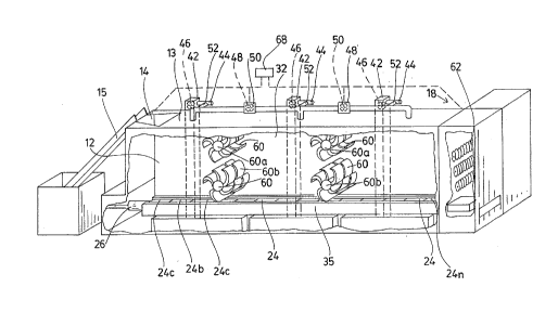
The drawings illust:rate a composter 10 comprislng
a tunne] 12 having a top 13 and an input port 14 in an
upstream end 16 of top 13. A conveyor 15 lifts garbage to
deliver it to input port 14. The downstream end 18 of
tunnel 12 has a doorway 20 for outputti.ng compost. W:ithin
the tunnel 12, tracks 22 are provided to each side of the
tunnel supporting conveyor trays 24a - n. The c.onveyor
trays 24 move stepwise through the tunnel in a longitudinal
directi.on on the conveyor tracks.
Before describing the details of the apparatus it
may be useful to describe briefly the operation thereof. A
conveyor tray 24a is located on the tracks 22 un.derneath
the mixing hopper 14. Garbage is added fro~ the conveyor
15, through slidin~ door 17 to a suitable depth in tray
24a, say within a foot of the roof of tunnel 12. The tray
24a is then stepped forward by action of a ram 26 having a
stroke sufficient to move tray 24a forward sufficiently to
' CA 0208930~ 1997-10-21
allow space for a further tray 24_. Ram 26 is then
withdrawn and tray 24 is inserted between the ram and tray
24a. The number of trays and the length of the tunnel may
be such that composting is complete when a tray 24 reaches
end 18 of the tunnel. The compost may then be removed from
the tray by conveyor 25 and the tray may be returned to the
input end. Tray return may be manual or may be automated.
When tray return is automated, each tray exiting from a
tray exit port 20 may be ejected onto a conveyor to return
the tray to the upstream end of the composter 10.
Conveniently, the size of the tunnel and the size of
the trays may be such that each tray may take a day's
supply of garbage. It is suggested that under good
conditions of composting fourteen days will be sufficient
to make compost and thus the line of conveyor trays within
the composter may be fourteen as shown although other
numbers of trays are possible. The operation of the
composter will be described in greater detail with
reference to the apparatus parts hereinafter.
Sliding door 17 is shown in more detail in Figure 6.
Sliding may be conveniently in an upstream downstream
direction in tracks 19 with closing being in the upstream
direction. Whatever the direction of operation of door 17
it is found of operation of door 17 it is found convenient
to taper it to narrow in the direction of closing. Tracks
19 are correspondingly tapered. As tapered door 17 closes
in tapered tracks 19 it nests snugly into the tracks to
make a tight seal. Rubber sealing means may also be
provided.
Each conveyor tray 24 comprises a frame 27 and
foraminous surface 28 through which air can access the
garbage to be composted. The foraminous surface 28 is
located above frame 27. Trays are added to the train or
trays at the upstream end of the tunnel 12 through tray
entry port 21. Tray 24a, which is acted upon by ram 26 to
- CA 0208930~ 1997-10-21
advance a step within the tunnel, acts on tray 24_
downstream of it to advance tray 24_ also. Similarly, tray
24_ acts on tray 24c. Thus the trays are shunted down the
tunnel until tray 24_ is shunted out of tray exit port 20.
Since these trays are subject to considerable stresses,
initially imparted from ram 26 against the frames 27, these
frames 27 are built to withstand these stresses. Sidewalls
30 are of sufficient height to be impacted by the front
face of ram 26. Ram 26 conveniently accesses the most
upstream frame through tray entry port 21. In practice, it
is not necessary that walls 30 should be very high. It is
only necessary that they have a vertical area to
accommodate the driving face of ram 26 so as to absorb its
whole force.
The other pair of tray sidewalls 32 located
longitudinally in the tunnel are conveniently made as
sturdily sidewalls 30. However, these walls 32 do not have
to absorb the full force of the ram against their planes.
While considerable crumpling force may be exerted on them
in movement of the trays along the tunnel, this force is
somewhat mitigated by the presence of garbage in the tray.
The frame 27 comprises two pairs of opposed
sidewalls 30, and 32. One pair of these sidewalls 30
extend transversely across the tunnel 12 in upstream and
downstream locations. Ram 26 impacts the upstream sidewall
30 directly. Downstream sidewall 30 impacts the next
upstream sidewall 30 of tray 24_. Thus, the trays 24 are
shunted stepwise in a downstream direction by each stroke
of ram 26.
The opposed pair of sidewalls 32 run on tracks 22
carried by the walls 36 of tunnel 12. Conveniently the
slide 22 each comprise a U-section channel (see Figure 4),
the web 35 of which is attached to the respective tunnel
wall 32. The web 35 of slide 22 is wide enough that the
whole height of tray sidewalls 32 may be accommodated
CA 0208930~ 1997-10-21
within the U-section while resting on carrier U-leg 37a and
covered by cover U-leg 37b. The bottom of each tray
sidewall 32 may conveniently be provided with a layer of
polytetrafluoroethylene or other such material to reduce
friction between the trays 24 and the carrier leg 37a of
channel 22.
The tunnel 12 and the trays 24 may be sized
according to the amount of garbage to be handled. Given
that, under good conditions, composting may be achieved
within fourteen days, it is convenient to provide one tray
per day in the composter. Thus, if 200 pounds of garbage
is to be handled per day, the tray size and tunnel size
should be such that one tray will accept 200 pounds of
garbage. The ram size and ram pressure must clearly also
be suitably adjusted to moving the entire train of trays
within the tunnel. It is, however, emphasized that a
composter according to the invention may be designed for a
very small domestic operation or for a very large
industrial operation. The mechanics and engineering of
tunnels and trays of suitable sizing are well within the
scope of a man skilled in the art.
The tunnel 12 is provided with various composting
aids along its length. Such as aerators and mixers to
loosen and rearrange the garbage. Moreover, means may be
provided to recycle at least some of the gases produced
during composting, thereby filtering and reducing the total
amount of unpleasant, noxious gas.
As illustrated, the tunnel is effectively divided
into three zones Z1, Z2 and Z3. An aerator is provided in
zone Z1 and again in zones Z2 and Z3. Each aerator
comprises a vertical duct 42 extending downwardly outside
the tunnel 12 adjacent to sidewall 32. The duct 42 draws
air from the exterior through an inlet pipe 44 by means of
a fan 46. This air is transported down the duct to below
the level of the conveyor trays 24 into a header 43 in the
- CA 0208930~ 1997-10-21
respective zone Z1, Z2, or Z3. From each header 43 the air
is distributed through composting garbage in the respective
zone. A further fan may be provided at the bottom of the
duct 42. Exhaust ducting 48a, b, c is provided at the
top of the tunnel in each zone for the removal of the air
and gases produced during composting. Exhaust fans may be
located in the exhaust ducting. Surprisingly, it has been
found that the addition of a proportion of the exhaust
gases to the aerating gas passed down duct 42 is beneficial
to the composting process. The exhaust gases contain an
appreciable amount of unused oxygen, and it is possible
that, apart from the addition of oxygen, one affect of
recycling the exhaust gases is to enhance the lightening
effect of the aeration and to help prevention and
compaction of the garbage. Another important benefit of
using recycled exhaust gases through branch tube 52 is that
the exhaust gases are heated due to the bacterial action in
the garbage. In zone 1 where the garbage is fresh and
cool, it is possible to use aerating gas which may be as
much as 100~ recycled exhaust gas. This may help to heat
up the garbage to optimum composting temperature. As soon
as bacterial action is substantial, the composting garbage
is warm and it may be beneficial to use as much as 100
cool, fresh air to maintain the temperature of the
composting process at its optimum. As soon as the garbage
is warm, the aerating gas may include as much oxygen as
possible for maximum composting. As the composting
progresses, the proportion of recycled gases to fresh
aerating gas varies dependent on the length of the
composting period and composition of the garbage.
Of course, a varying number of zones may be used
in apparatus according to the invention, and the
description relating to three zones is exemplary only.
As the compost in trays 24 travels along the
tunnel 12 it may tend to settle slightly. Moreover,
composting may not be even throughout the heap of garbage
on each tray. It is, therefore, desirable to mix the
CA 0208930~ 1997-10-21
material in order to loosen it, aerate it, mix it, and
generally improve composting conditions. For this purpose,
mixing rollers 60 may be provided extending across the
tunnel 12. These mixing rollers 60 may extend from
sidewall to sidewall of the tunnel 12 and may have drive
shafts extending through the side of the tunnel to be
powered by any convenient means (not shown). As
illustrated, two mixing rollers, 60a and 60_ are provided
one above the other, in the end region of zone Z1, and in
the end region of zone Z2. However, it will be appreciated
that mixing rollers can be provided at whatever distances
along the tunnel are thought suitable.
The mixing rollers may be of any suitable form
and, indeed, need not be rollers but may be any device to
mix the compost. As illustrated, the rollers 60 are
provided with paddles 62 to catch and circulate the
garbage. The mixing rollers 60 may rotate on drive shafts
in similar or opposed directions.
At the end of zone Z3, three augers 62 are
provided one above the other to transport the formed
compost into a side tunnel annex 64. In annex 64 the
compost delivered from the augers 62 falls onto a conveyor
25 and is removed through sliding door 66.
The whole process may be subject to computer
control by computer 68. Computer 68 calculates and
controls the proportions of exhaust gas and fresh aerating
gas delivered into each of the zones Z1, Z2 and Z3, and may
also control opening and closing of sliding doors 17 and
66. Generally, sliding doors 17 and 66 are only permitted
to open when conveyors 15 and 25 respectively are in
operation. At all other times, the tunnel is effectively
completely sealed. An entry is provided for the trays 24
and an exit port 20 is also provided; but, when trays 24
are in position within the tunnel 12, the frames
effectively block and close the entry and exit ports for
2089305
-- 10 --
the trays. The computer 6B may also ensure that the
pxessure of aerat;ng gas, with or without an exhaust gas
component, is ~aintained lower than the suction pressure
removin~ exhaust gas. If the pressure within the tunnel is
maintained less than the atmospheric pressure, any leaks in
the syste~ will not result in the escape of nox;ous odouxs.
As the trays progress stepwise through the tunnel
the volume of compost;ng garbage decreases. Thus, tray 24a
is loaded to within, perhaps, one foot of the roof of
tunnel 12. This volume may have decreased to 40% of the
original by the time the tray has reached the position of
tray 24n. It may be possible by use of the mixers, or by
use of additional augers acting longitudinally, to provide
some mixin~ of material from tray to tray without detriment
to the composting process. Such mixing may help to move
material to maintain a more even level in the tunnel. At
least, additional mixing may provide greater aeration and
lift and hasten compostin~ in the downstream trays.
The longitudinal and volume dinensions of the
tunnel are purely a matter of choice. It is for
convenience that the system has been described with
reference to a tunnel of length to accommodate fourteen
trays, one txay being util;zed for each day's garbage. If
a regular supply of garbage is available, this system is of
convenience to the operatc)r irrespective of the amount of
garbage being delivered per day. Thus, if an operator can
rely on say, 200 pounds of garbage per day, the system may
be designed so that each tray will accommodate 200 pounds
of garbage. In such a system there is little need to check
whether a tray is being overloaded and whether it is time
to install a new tray. Tt wlll, however/ be appreciated
that when the supply of garbage is irregular there will be
a need to advance the train of trays only when the tray 24a
directly under the hopper 14 is filled to a suitable
capacity. The decision as to when this point occurs may be
made by visual inspection, or other automated means may be
2089305
installed to warn the operator that a step forward of the
tray train is desirable.
Again, the choice of fourteen ~ays ~or fourteen
trays) as the length of the tunnel is by no means limiting.
Under good conditions compost may be made in fourteen days,
but given suitable strength of trays and suitable force of
the ram there is no objection to compost remaining in the
tunnel for a greater length of time. This will, of course,
extend the length of the tunnel beyond that minimally
necessary.