Note: Descriptions are shown in the official language in which they were submitted.
WO 92/05638 r~ u~ VVJ
,.
- 208~37~
10 VARIABLE SPEAKER MUTING BASED ON RECEIVED
DATA
Technical Field
This invention relates generally to speaker muting
techniques in voice communications systems and more
particularly to an intelligent speaker muting method and
apparatus that is particularly well adapted for use in radio
communications systems.
Backqroùnd
Current radios function in channel environments that may
contain data, clear voice, and coded or encrypted voice
transmissions. For each one of these types of transmissions there
is an associated attack time (i.e. the data detector takes a certain
amount of time to detect) at the receiving subscriber unit. The
coded voice detector may take some time to detect encrypted
voice which may require more time than for clear voice to be
detected.
Conventionally, the receiving subscriber unit cannot tell
which type of signal will be received next. Currently, in receivers
of a voice communication systems data muting typically has been
accomplished by detecting a presence of a data signal and then
muting the output of the receiver so that it is not heard, regardless
of the following signal. As described in U.S. Patent No. 4,430,742
the data muting is terminated whenever the last
bit of the data signal has been
WO 92/05638 PCI/US91/05663
2089370
detected (prior art #2 as seen in FlGs. 2A-C). Many different
techniques exist for detecting the presence of the data signal
such as detection of a word sync (as illustrated in Patent No.
4,430,742) or in some improved methods, the detection of a bit
5 sync (as illustrated by as prior art #2 as seen in FlGs. 2A-C as
another example). In addition, a timer is also used to- mute the
speaker for some time period (prior art #1 illustrated in FlGs. 2A-
C) starting from the reception of a carrier signal and ending when
data has been detected.
However, since techniques of data muting requires the
reception of several bits in order to detect a data signal (attack
time), a short data burst is heard by the listener with the exception
of the data received in the first data packet (as covered by prior art
#1 of FlGs. 2A-C). Since the peak to peak signal level of the data
signal is very high for reliability reasons, the data bursts are very
loud during peak periods of data traffic in such communication
systems. These data bursts are then very annoying to the
listener.
In the case of coded voice transmissions, there is also
associated with it an attack time to decrypt the coded voice signal
which results in another short data burst, which is again passed to
a listener. The effect of this data burst or squelch head can be
removed by muting the output of the receiver (setting a fixed
speaker mute delay) for a fixed time period that is long enough to
include the decryption of the coded voice signal. The fixed time
period would be set after a received data packet or at the
beginning of the received signal (prior art #1 of FlGs. 2A-C). This
method can also mute the data bursts caused by the attack time of
multiple data packets as described previously.
However, the problem with this fixed period method is that
the delay has to be set at the maximum attack time for the various
transmission signals. If a clear voice signal is sent instead, this
fixed delay might cut off the beginning of the clear voice
transmission after a data packet. Since the fixed time period must
be made long enough to accommodate system delays and the
WO 92/05638 2 0 8 9 3 7 0 PCI/US91/05663
longest attack time, clear voice communications having a shorter
attack time and following the data signal will also be muted.
Therefore, there is a long felt need for a data muting
method and apparatus that mutes the entire data signal along
with unwanted data bursts without muting the following voice
communications.
Summary of the Invention
Accordingly, it is an object of the present invention to
transmit information that incJicales which type of signal is to follow
(clear voice, coded voice, or data) such that the receiving
subscriber unit can s~bst~ntially mute all of the unwanted data
bursts and allow the maximum amount of voice data to be
retained.
Briefly, according to the invention, a method and an
apparatus for controlling a speaker mute time is provided to
transmit an information message from a first communication
device to a second communication device. In response to
receiving the information message, the second communication
device controls the duration of its speaker mute time.
Brief Description of the Drawinas
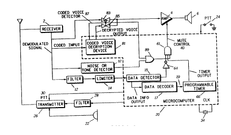
FIG. 1 is a block diagram of a mobile or portable radio in
accordance with the present invention.
FlGs. 2A-C are timing diagrams for the signals from
selected blocks in FIG. 1.
Detailed Description of the Preferred Fmbodiment
Referring to FIG. 1, there is illustrated a block diagram of a
mobile or portable radio that may communicate with another
mobile or portable radio or with a central station. As used herein,
the term subscriber units or communication device collectively
refers to portable units, mobile units or control (central) stations.
Subscriber units, therefore, may be mobile units, portable units, or
control (central) stations. Generally, a portable subscriber unit is
designed to be carried on or about the person, a mobile
WO 92/05638 2 0 8 9 3 7 0 - PCr/US91/05663
~ -, 4
subscriber unit is designed to be mounted into vehicles, and
control stations are permanent or semi-permanent installations
installed in buildings or other fixed locations.
The subscriber unit employs the data muting apparatus of
the present invention. The radio includes a microcomputer or
microprocessor 20 which may be a suitable conventional
microcomputer, such as for example a Motorola type 68HC11 or
its equivalent, for controlling the operation of a receiver 2 and a
transmitter 26. As illustrated, the microcomputer may include a
coded voice decryption device 81, a data detector 15, a data
decoder 17, a programmable timer 66, and associated mute
control logic circuitry (an AND gate 61, an inverting gate 64, and
an OR gate 89) which may all be implemented by software. The
frequency of operation of the microcomputer 20 is determined by
a crystal 34.
In subscriber units, voice communications are provided by
means of a speaker 6 and a microphone 22. Whenever a
subscriber wishes to speak to another subscriber or a d;cp~lcher
at the central station a push-to-talk (PTT) switch 24 is activated.
The microcomputer 20 senses the activation of the PTT switch 24
and correspondingly enables the transmitter 26 by means of a
PTT signal 30 and serially couples successive bits of a data
signal to a filter 28 for application to the transmitter 26. The data
signals transmitted between the central station and a mobile or
portable radio or between the radios themselves include a bit
sync portion, a synchronization word, and an information word.
According to the invention, the information word may include
commands and/or status information to control the duration of the
speaker mute time by way of the programmable timer 66.
The data signal transmitted by the microcomputer 20 also
indicates to a receiving subscriber unit or a dispatcher at the
central station that a particular mobile or portable radio desires to
communicate with the dispatcher or another receiving subscriber
unit.
In the receiving end, the demodulated signal from the
receiver 2 is coupled to a filter 12 and a limiter 14 for providing a
WO 92/05638 2 0 8 9 3 7 0 PCI-/US91/05663
signal which is coupled to the data detector 15 to generate a first
output as a data information output and a second output which
indicates the presence or absence of a data signal. The digital
signal which indicates the absence or presence of a data signal
5 from the data detector 15 is coupled by way of the inverting gate
64 to a first input of the AND gate 61 to mute a speaker 6 while
the data signal is present. The muting is accomplished by means
of a mute control signal 40 (output of the AND gate 61 ) which
disables an audio amplifier 4 unless all of the inputs to the AND
10 gate 61 are high.
The data information output, from the data detector 15 is
coupled to the data decoder 17 for recovering at least the
information word which contains information associated with the
type of signal following the data signal. The bit sync portion
15 allows the receiver 2 to attain clock synchronization. The
synchronization word may consist of any suitable correlatable bit
pattern. The information word may have a variable number of bits
to form an information field which includes commands and/or
status information such as a command to fix the time delay or
20 status information to say which type of signal is following the data
signal. The information word may be arranged in any suitable
format.
The data decoder 17 can thus decode the status included
in the information word denoting that a data signal is following the
2~ present data signal as one time variable to be set (19) in the
active low programmable timer 66. Similarly, the status of a clear
voice signal following the present data signal will be decoded by
the data decoder 17 to set a different time interval in the
programmable timer 66 if necessary. The status of a coded voice
30 signal following the present data signal as decoded in the data
decoder 17 will result in a longer time interval than the clear voice
interval to mute the speaker during decryption of the voice signal.
Instead of status information, the information field of the
information word can actually provide the information to program
35 the programmable timer 66 for the particular time interval. Only
WO 92/05638 2 0 8 9 3 7 0 PCI/US91/05663
three different time intervals are provided in this embodiment, but
less or more intervals may be provided as necess~ry.
The signal from the data decoder 17 is coupled to the
trigger input of the programmable timer 66. The active low output
5 of the timer 66 (See waveform 210 in FlGs. 2A-C) is triggered by
the content of the received data signal and is coupled to a second
input of the AND gate 61 for causing the mute control signal 40 to
have a zero state for a variable or programmable time interval (set
by the timer 66 based on the content of the information word
10 which relates to the type of signal following the information word).
After the time interval or delay provided by the the output of the
timer 66, the mute control signal 40 (output of the AND gate 61 )
will change state to a binary one state (as long as the other inputs
are high) for enabling the received signal path. Thus, the
15 received signal path is always muted for at least the time duration
of the output of the timer 66.
The voice portion of the demodulated signal from the
receiver 2 is coupled to the audio amplifier 4 by way of either one
of two digitally controlled analog gates 83 or 85, depending on
20 whether the voice is coded as detected by a coded voice detector
87. If coded voice is present, the coded voice is coupled to the
coded voice decryption device 81. The decrypted voice output
from the coded voice decryption device 81 is coupled to the audio
amplifier 4 by the gate 85 enabled by the coded voice detector 87
25 which also disables the gate 83 at the same time. If a clear voice
is present instead, the absence of the encryption enables the
inverted analog gate 83 to pass through the clear voice from the
receiver 2 into the audio amplifier 4.
The demodulated output of the receiver 2 is also coupled
30 to a noise or tone detector 10 which provides a noise signal
indicating the presence or absence of an RF carrier signal. When
an RF carrier signal appears, the coded voice detector 87 and the
output from the noise or tone detector 10 are both coupled to the
OR gate 89 to provide a third input to the AND gate 61 in order to
35 unmute the speaker 6. The unmuting is accomplished by means
of the mute control signal 40 (output of the AND gate 61 ) which
WO 92/05638 2 0 8 9 3 7 0 PCr/US91/05663
enables the audio amplifier 4 subject to the other inputs to the
AND gate 61.
The mute control signal 40 then enables the audio
amplifier 4 after a particular time interval has passed depending
5 on the status or command signal included in the information word
recovered by the data decoder 17. After the time interval set by
the programmable timer 66 (depending on the status or command
word, sent by the transmitter of the received signal, specifying the
type of signal following the data signal) has passed, voice
10 communications can take place between the subscriber and
another subscriber.
Referring to FlGs. 2A-C, operation of the subscriber units is
depicted by waveforms where the transmit end waveforms 202
and 204 correspond to signals at a central station or a mobile or
15 portable radio that is sending out or transmitting information. At
the receiving end, wave forms 206, 208, 210 and 212 correspond
to signals at the receiving mobile or portable radios. The noise or
tone signal waveform 206 corresponds to the noise or tone detect
signal from the noise or tone detector 10 in Fig. 1 and the mute
20 control signal wave form 212 corresponds to the mute control
signal 40 provided by the microcomputer 20 in Fig. 1. The data
detect waveform 208 and timer waveform 210 correspond to
internal timing signals of the microcomputer 20. Many different
techniques exist for detecting the presence of the data signal
25 such as detection of a word sync or in some improved methods,
the detection of a bit sync as is illustrated by waveform 208 as an
example. The present invention can work with any type of
detection method.
The waveforms of Figs. 2A-C illustrate an important feature
30 of the present invention where the speaker muting is varied for a
time duration sufficient to mute the attack time associated with a
data signal, clear or coded voice signal along with a system delay
time without muting any of the voice information. The system
delay is the time difference between different data or voice
35 messages. The attack time is the delay from the reception of a
signal to its detection. Hence, the timer waveform 210 and the
WO 92/05638 PCI/US91/05663
208Y370
mute control signal waveform 212 are varied according to the
status or command fiéld inside the information word of the data
waveform 204, to change or not change states for unmuting the
voice signal path. Thus, since muting is continued until the time
5 specified by the command or status field inside the information
word depending on the signal following the information word, the
data muting apparatus of the present invention can accommodate
data, clear voice and coded voice.
According to the present invention, as illustrated in Fig. 2A,
10 based on the status or command field specifying "data" (D)
included in the information word of the present data signal 204,
the duration (system delay + attack time) of the programmable
timer 66 controlling the mute control 40 is set for a time duration
A. The duration A is calculated by adding the attack time of the
15 data detector 15 to the system delay. In duration A, the system
delay is defined as the time between data packets. Based on
either a word sync or a bit sync detection algorithm, the time that
the data detector 15 requires to detect the presence of the data
signal in duration A is called the attack time. This duration A
20 would then mute the speaker 6 to substantially avoid any data
bursts associated with the following data signal.
In Fig. 2B, the duration of the programmable timer is set at
the end of the information word for a duration B (covering both the
system delay and attack time) starting and ending anytime
25 between and including the end of the information word and the
beginning of the following clear voice signal. There may be no or
a slight attack time (as shown by the dashed lines) associated
with detecting a clear voice signal. This duration B is based on
the status or command field associated with the following clear
30 voice signal (C) included in the information word of the signal
204.
In Fig. 2C, the duration of the programmable timer 66 is set
for a duration C according to the status or command field
associated with a coded or encrypted voice signal (E) of the
35 signal 204. Duration C (covering both the system delay and
attack time) starts from the end of the information word to
WO 92/05638 PCI/US91/05663
2089370
sometime during the coded or encrypted voice signal which is
sufficient to decrypt the following coded or encrypted voice signal.
This duration G would then rnute the speaker 6 to substantially
avoid any data bursts associated with the following encrypted
5 voice signal. In this manner, a listener is prevented from hearing
the decryption of the coded voice signal.
In summary, an intelligent speaker muting method and
apparatus has been described that eliminates the annoying data
bursts c~used by data signals and encrypted voice signals in
10 communications systems which includes data, clear, and coded
voice communications. The intelligent speaker muting method
and apparatus mutes the signal received by a receiver for the
duration determined by the status or command field inside the
present data signal without muting the following audible voice
15 signal. Since the speaker muting can be varied, the intelligent
speaker muting method and apparatus of the present invention
can accommodate variable time duration depending on whether
the following signal is another data signal, a coded or a clear
voice signal. The intelligent speaker muting method and
20 apparatus can advantageously be used in radio or land line
communication systems where both clear or coded voice signals
and data signals are communicated between a central station
and a plurality of remote stations.
What is claimed is: