Note: Descriptions are shown in the official language in which they were submitted.
WO 92/2296b ~CT/SE92/00403
1
A t~REET~iOD AND APPARATUS FOR ESTIMATING
INITTAL TIME ALIGNMENT , .
IN A CELLULAR COMMUNICATIONS NET6dORK' _
FIFI~ OF ~fHE IPI~ENTIO~1
The present invention relates to the estimation of an initial
time alignment parameter in cellular mobile radio systems. lore
particularljr, the present invention is directed to a method and
apparatus for estimating the initial time alignment parameter
when setting up a call or a handoff of the mobile station to a
new base station in a cellular mobile radio system.
~,ACKGROUND OF TH~ TNV~NTIOFd
Time alignment is the process of controlling the time of TDMA
time slot burst transmission from the mobile station by advancing
or retarding the mobile transmit burst so that it arrives at the
base station receiver in a proper time relationship to other t~.me
slot burst transmissions. Time alignment applies to TDMA
channels in the direction from mobile to base station. An error
in time alignment may cause the arrival of signals from two
different mobile transmitters simultaneously at the base station
receiver. This in turn causes errors in both signals. This
overlap can occur at the beginning or end of a time slot. Upon
detecting an overlap condition, the base station sends an
appropriate time alignment message to the mobile station using
the appropriate forward control signaling channel.
According to the Section of the IS°-5~, December 19&9, defining
system access, the mobile station receives an initial traffic
channel designation message and sei2es a traffic channel. The
mobile station transmits a shortened time slot burst at a
predetermined time until it receives a time alignment message
from the base station or the mobile station is directed to stop
transmission due to other considerations. The burst sent by the
mobile is artificially shortened in order to reduce the chances
~~~~e~~3~~
CVO 92!22966 PCf/5E92/~D04U3
2
for signal overlap. If the mobile station receives a time
alignment message, it adjusts its transmission timing and
transmits during the next available slot a time-aligned, full
duration slot burst.
Thus, the time alignment parameter is initially reset to zero and
adjusted to an optimal value in typically about one to four
seconds. By the time the alignment parameter is adjusted, a
number of bit errors may have already occurred due to burst
overlap.
At handoff of a mobile station to a new base station, the
distance between the mobile station and the tcurrently active)
base station which coordinates communications with that mobile
changes abruptly, requiring a change of the absolute time
alignment offset parameter in the mobile station. At handoff,
the time alignment offset parameter is either reset to zero which
is the value associated with the mobile station being near the
base station, or the old time alignment offset parameter is not
modified. Then, the time alignment parameter is adjusted by
measuring the time when a burst is received at the new base
station, based on the sync pattern in the burst, and a change of
the time alignment offset parameter is ordered responsive to this
measurement. This change typically takes about one to four
seconds. During this delay, there is an increased probability of
disturbing other time slots due to burst overlapping.
SUMMARY 8F TES I1,IVETf~ION
In order to overcome the disadvantages noted with conventional
procedures, a preferred embodiment of the present invention is
directed to a method in a mobile radio system for initially
setting a time alignment parameter in a mobile station comprising
the steps of estimating an optimal time alignment parameter for
use during communication on a new traffic channel of a desired
base station based on information available before the com-
munication is established, and sending the estimated time
alignment parameter. to the mobile station. According to one
' V5r0 92/22966 P(.'T/SE92/(i0403
3
embodiment, the estimation is performed upon receipt of a handoff
reejuest and the estimated time alignment parameter -is sent with
the handoff order. According to another embodiment, the
estimation is performed upon receipt of an access rec~eaest or page
response and the estimated time alignment parameter is sent with
- a physical layer control message immediately on the new traffic
channel.
According to embodiment of the present invention the information
available used to estimate the optimal time alignment parameter
is at least one of the following values: ~a handoff boundary
angle value, a handoff distance value, a total distance value or
a current time alignment value. Additionally, pathloss may be
used in the time aligrunent estimation. ~
According to a preferred embodiment of the~present invention, an
apparatus is provided in a mobile radio station having a
plurality of cells, for initially setting a time alignment
parameter in a mobile.station. The apparatus comprises means for
estimating an optimal time alignment parameter for~use during
communication on a desired traffic channel of a desired cell
based on information available before the communication is
established, and means for sending the estimated time alignment
parameter to the mobile station.
Still other objects,.features and attendant advantages of the
present invention will became apparent to those skilled in the
art from a reading of the following detailed description of the
embodiments constructed in accordance therewith, taken in
conjunction with the accompanying drawings.
~ HRIEF DESCRIPTIOIJ OF TRH DRI~RIIJGB
The present invention will now be described in more detail with
reference to the preferred embodiments of the device, given only
by way of example, and with reference to the accompanying
drawings, in which:
WO 92/329Gb ~ ~ ~ ~ ~ ~ ~ PCi'/5E92/004~D3
a
Fig. 1 illustrates a situation where a handed-off mobile station
or a newly accessing mobile station enters a new cell where the
mobile radial distance from a site is approximately known and
cell geometries are known;
Fig. 2 illustrates a situation where a handed-off mobile station
or a newly accessing mobile station enters a new cell for which
not much is known about the mobiles location or cell geometries
are unknown;
Fig. 3 illustrates a handoff between two overlapping cells;
Fig. a. illustrates a handoff of a mobile station from a micro-
cell to an umbrella cell:
Fig. 5 illustrates an underlay cell and an overlay cell where
reuse partitioning is used:
Fig. 6 illustrates handoff of a mobile station from sector to
another sector within one base station;
Fig. 7 illustrates a time slot on a digital control channel;
Figs. SA and ~5 are flowcharts illustrating methods according to
one embodiment of the present invention;
Fig. 9 is a signal description illustrating the system and air
interface signalling performed with respect to initial time
alignment during handoff:
Fig. l0A and lOB are flowcharts illustrating methods according to
other embodiments of the present invention;
Fig. 11 is a signal description illustrating signals sent during
call set up in cases of analog and digital control channels;
Fig. 12 illustrates a top view showing cell geometries and
distances between two neighboring cells:
~-~ p~,T/~E92/00403
- WO 92/22956
Fig. 13 illustrates a intracell handoff where distances can be
estimated using known distances between neighboring.. cells;
Fig. 14 is a block diagram illustrating a mobile station in a
cellular mobile radio system:
S Figs. 15A and 15B are block diagrams illustrating a base station
in a cellular mobile radio system: and
Fig. 16 is a block diagram illustrating ~ mobile switching center
in a cellular mobile radio system.
DETAILED DESCRIPTIOpJ -daF TH$ PREFERRED E1~1B~DIPd.BIdTB
According to the present invention, when a mobile station starts
communicating with a certain base station, an estimate for an
optimal initial time alignment parameter is made by the land
system, either by the base station or by the mobile switching
center and the corresponding correction is sent to the mobile
I5 station. In a preferred embodiment, the estimate is made by the
base station. According to preferred embodiments of the present
invention, the estimate may be done in several ways using
information available to the land system before uplink bursts on
a new voice channel, that is, bursts from the mobile station to
the base station, are transmitted.
Two methods may be used during call initiations or in an inter-
cell handaff situatian (unless the new and old base stations are
co-located). In a situation such as shown in Fig. I, the
knowledge of the cell geometries allows an initial time alignment
parameter iTA to be defined which minimizes the probability of
burst overlap between mobile stations. In a preferred
embodiment, it can be assumed that a ne~a mobi3.e station or a
handed-off mobile station is at a distance of one half the cell
radius from the entered base station BS, represented in Fig. 1 by
the dotted line A. The resulting estimate of an optimal time
alignment parameter is a cell constant.
~~~~~J~
WO 92/22966 PCT/5~92/00403
6
In a situation such as shown in Fig. 2, the base station measures
the signal strength of the first uplink burst or bursts and the
optimal time alignment parameter is a function of. the measured
signal strength. For example, the signal strength is measured
for the access of a new mobile station on a control channel, or
the signal strength measurements of the new base station prior to
handoff to a digital traffic channel can be used. This allows
calculation of the pathloss which can be used to estimate the
distance to the base station. Equations for relating the
i0 pathloss to a distance are known which can take into account
information about the type of topography, characteristics of the
frequencies used, as well as the antennas heights and output
power. One such propagation tool which can be used in a
preferred embodiment of the present invention is described by
Masaharu Hata in,~EEE Transactions on Vehicular Technoloav, Vol.
VT-29, No. 3, ~rugust 1980, incorporated by reference herein. The
resulting estimate of the optimal time alignment parameter is a
function of the mobile station position or pathloss.
In an inter-cell handoff situation where the new and old base
stations are not co-located, another method may be used.' This
method is not preferred when setting up new calls. In the.
situation shown in Fig. 3, the land system knows the old time
alignment parameter and uses it to estimate the distance from the
mobile station to the old base station. The land system also
knows the cell geometries and the~most probable route for the
mobile station in the direction of the new cell, based on traffic
measurements (i.e., highways through the cell). The estimate of
the new optimal time alignment parameter is then a function of
the mobile station position or pathloss. In the special
' situation illustrated in Fig. .d, where handoff is from a micro
cell to a large umbrella cell, the location of the mobile station
in the umbrella cell can be estimated with a large degree of
certainty (since a micro-cell is relatively small in relation to
an umbrella cell). The resulting estimate of an optimal .time
alignment parameter is thus a function of the micro-cell's
position relative to the umbrella cell site which is known and
can be defined as a cell constant.
~ ~ J
- W~O 92/22966 PC1'/SE92/00403
7
In situations requiring handoff where the new and old base
stations are co-located, the old time alignment parameter can be
maintained because the distance to the base station does not
change since the same base station is used. For example, this
method may be used for handoff between underlay/overlay cells
when using reuse partitioning as shown in Fig. 5, (where reuse
distance da is different from reuse distance da) , for handaff
between sector cells as shown in Fig. 6, or for intracell
handoffs (handoff between voice/traffic channels in the same
cell).
For setting up new calls, either originating or terminating
calls, the base station measures the time position of the uplink
access burst sent by the mobile without time alignment correction
(an access burst on a digital control channel) as illustrated in
Fig. 7. It is assumed, for thus case, that time alignanent
control will not be a part of the digital control channel
structure. So when the actual synch word position is detected to
be shifted from the reference synch position, the amount of this
shift can be directly translated into propagation delay, or
distance in a known manner. This distance can then be used on
the new voice channel for the initial time alignment parameter
iTA.
It is also possible to perform a combination of the methods
described above for inter-cell handoff where the new and old base
stations are not co-located and the method described for new
calls to determine a new time alignment parameter. More detailed
discussion of the methods according to the present invention
fol lows .
The following definitions and abbreviations are used throughout
this disclosure. The entry distance is a term used for the
actual straight-line distance in kilometers between the mobile
station which is being handed off and the new base station which
is to receive the mobile station communication< The iTA is a
temporary variable associated with the initial time alignment
value. Its value is calculated from the entry distance and then
~~~~~~~a
iVfl 92/22965 PC.'T/SE92/00403
8
inserted as the time alignment field in handoff and channel
initialization messages. H08A~dG is the handoff boundary angle
relative to a straight lane path between two neighboring cells.
If the two neighboring cells are omni-directional, then a
boundary angle of 90i can be assumed. This may not be true for
two sectored cells intersecting at an angle. See Fig. 12.
FiODIST is a parameter that defines the handoff distance in
kilometers into a specific cell from one of its neighbors. The
defined distance may represent either the direct or the highest
or average traffic route into the cell. ICDIST is a parameter
that defines the total distance in kilometers between two
neighboring sites. This can be determined directly from their
site coordinates. PhLC is ari abbreviation for °physieal layer
control' which is one of the message types defined by IS-54 for
the digital traffic channel.
Figs. 8A and 8B are flow charts describing a first embodiment of
the present invention. The flow charts of Figs. 8A and 8B begin
at the point where a handoff request is generated from either an
analog or digital voice (traffic) channel and end at the point
where a mobile uses the time alignment value sent with the
handoff order.
As the first step in this method, the base station, upon
determining that a handoff is necessary, sends the mobile
switching center a handoff request (step 200). A processor in
the mobile switching center MSC receives or determines possible
candidate cells to receive the handoff (step 202). The MSC
processor may then verify and select one of the candidates for
handoff (step 204). At step 20C, a channel in the candidate cell
is selected for transmission. In the succeeding steps, the type
of channel and cell is determined. In particular, if the
selected channel is determined to be an analog channel at step
208, the routine ends and no estimated time alignment parameter
is determined. If the selected channel is digital,. at step 208,
it is determined whether the selected cell is the current cell at
step 210. If so, control passes to step 232. If the selected
cell is not the current cell at step 210, it is determined
f4'O 92/22966 PCT/SE92/00403
- 9
whether the selected cell is an overlay cell at step 212. If so,
control passes to step 232. If the selected cell is not an
overlay cell at step 212, it is determined whether, the selected
cell is an underlay cell in step 214. If it is, control passes
to stag 232. If the selected cell is not an underlay cell, it is
determined whether the selected cell is an adjacent sector at
step 216. Tf it is, control passes to step 232.. If the selected
cell is net an adjacent sector at step 216, it is determined
whether the current channel is a digital channel at step 218.
If the current channel is digital at step 218, the parameters
HODIST, ICDIST and HOBAY~G defined between the current cell and
the candidate cell are fetched from a memory at step 220. This
memory may be located either in the mobile switching center or in
the base station. At step 222, the entry distance is estimated
by using the HODIST, TCDIST and HOBANG parameters with the
current tame alignment value. At step 228, the variable iTA is
set by converting the estimated entry distance to absolute time
alignment units and the handoff order is sent at step 230 with
the time aligned field equal to iTA. The time alignment value, in
the mobile is then shifted or set equal to the time align field
of the handoff order, that is, to iTA at step 292.
At step 228, the entry distance is converted into time alignment
units (or half-symbols), according to a preferred embadiment, by
the following equation:
iTA = 2 -~ (1000 x entry distance) / (C ac bittime)
where: the factor of 2 expresses the roundtrip distance; 1000 is
used to convert entry distance to meters; C is the speed of light
in m/sec; and bittime is 1/48600 sec as defined by IS-54.
If it is determined that the current channel is not digital, at
step 218, that is, the current channel is analog, the parameter
HODIST defined between the current cell and the candidate cell is
fetched from memory and the entry distance is estimated by using
the HODIST parameter at step 226. The variable iTA is set at
step 228 by converting the estimated entry distance to absolute
time alignment units in accordance with the method described
bV~ 92/229b6 PCT/SE92/Oib403
3.0
above. The handoff order as then sent, at step 230, with.a time
aligned field equal to iTA. At step 242, the time alignment of
the mobile is set, or shifted, according to the value of iTA
received by the mobile an the handoff order.
If any one of steps 210 through 216 is answered in the positive,
it is determined whether the current channel is digital, at step
232, If the current channel is digital, the variable iTA is set
to maintain the present timing offset at step 240 and the handoff
order is sent at step 230 with the time aligned field equal to
iTA. At step 242, the time alignment is set in the mabile
according to iTA.
If the current channel is nat digital at step 232, step 234
calculates the pathloss of the mobile station from the signal
strength and power level. At step 236, all HODIBT parameters
defined between the current cell and its candidate cells are
fetched from the memory and the entry distance is estimated at
step 238 by using the HODIST parameters together with the handoff
type and mobile station pathloss. At step 228, the variable iTA
is set by converting the entry distance to absolute time
alignment units and the handoff order at step 230 is sent with
the time aligned field equal to iTA. The mobile sets its time
alignment to iTA at step 242.
Figure 9 is a signal description which shows the system and
interface signalling performed with respect to the initial time
alignment during handoff. At 2~0, after determining that handoff
is required, the base station sends a handoff request with
handoff candidates. The mobile switching center evaluates the
candidate list which leads to the selection of a cell and voice
channel. For simplicity, voice channel and traffic channel may
be used interchangeably in this description. The mobile
switching center uses the current and the selected cell and the
voice channel to determine how the iTA should be calculated. At
252, the mobile switching center sends the mobile a handoff order
with the time alignment field equal to iTA and at 254, the mobile
- 2~i~~~~>
_ w~ gzizz~ss PC'1'/S~9z/0~~3
11
station begins transmission on the new voice channel using a time
alignment of iTA. . .
Figures l0A and lOB are flowcharts of a procedure according to a
preferred embodiment of the present invention preferably carried
out for initial time alignment determination during call setup.
These flowcharts begin at the point where either an access or a
page response is received and describe the processes that lead to
the first time alignment adjustment on the new traffic channel.
Figuxe 10A'is preferrably used for analog control channels and
Figure 10B is used for digital control channels.
Figure 10A begins at step 300, where the mobile station performs
an origination access request or paging response and the base
station measures the signal strength of the access request or
paging response signal at step 302. If no voice channel is
available at step 304, the routine ends. If a voice channel is
available, the channel is selected and a voice channel desig-
nation is sent to the mobile station at step 306. The pathloss
of the mobile station is calculated from the signal strength
measured by the base station and the given power level of the
mobile, and the power level measured by the base station, at step
308. At step 310, all FiODIST parameters defined between the
current cell and its neighboring cells are obtained from memory.
At step 312, the entry distance is estimated using the HODIST
parameters together with a calculated pathloss. The variable iTA
is set by converting the estimated entry distance to time
alignment units at step 314, in accordance with the method
described above. A PhLC message is sent to the mobile stab~n
with the time alignment field equal to iTA immediately on the new
channel at step 316. At step 317, the mobile sets, or shifts,
its time alignment value in accordance with the time align field
received in the PhLC message.
As illustrated in Figure 108, which is preferably used for
transmission on digital control channels, step 318, the mobile
station performs an origination access request or
WO 92/22966 PCT/SE92/00403
12
page response and the base station measures the timesync error
during the access request or paging response signal at step 320.
If no voice channel is available at step 322, the routine ends.
Otherwise, a channel is selected and a voice channel designation
S is sent to the mobile station at step 324. The variable iTA is
estimated using the measure timesync error apt step 326 and the
mobile station is sent a Phr.C message with the time align field
equal to the iTA on the new channel at step 328. At step 329,
the mobile sets, or shifts, its time alignment value in accor-
dance with the time align field received in the PhLC message.
Figure 11 illustrates a signal description which has been
generalized to show the signal transmitted during call setup for
both cases of analog or digital control channels. At 330, the
signal strength or timesync error is measured by the base
station. At 332, the voice channel is selected and seized by the
mobile switching center. The mobile switching center then sends,
at 334, the measurements of the signal strength or timesync error
to the selected voice channel with the start order. At 33f>, the
new voice channel estimates the iTA from the cell parameters and
control channel measurements and at 338, the mobile station
begins regular transmission using a time alignment of iTA.
The calculations performed according to the present invention as
described above will now be discussed.
In Figure 8b, step 222, the entry distance is estimated according
to a preferred embodiment of the present invention in the
following manner. The current (old channel) time alignment is
known and used together with the cell parameters HODIST, ICDIST
and HOBANG to calculate the entry distance. Fig. 12 illustrates
a simplified approach to the problem of solving for the entry
distance by having the handoff boundary angle (HOBA3dG) of 90a .
However, even if the boundary angle is characterized by another
HOBANG value, the entry distance can still be estimated by using
the law of sines and cosines to solve for the unknown side length
in terms of the known quantities in the triangle shown in Fig.
12. The following equation may be used:
' ~~c~~~~::~
WO 92/22966 ~Cf/SE92/00403
13
main (Y)
.X= Sa+ (Va~t~ 2-2s(v+~ ~COS (Y-Sin' ~-----~ ---J )-
where X is entry distance, S is the old time alignment TA, U is
the HODIST parameter, V is ICDIST minus HODIST and Y is HOBANG.
This method could be used, for example, in the handoff case
presented by Fig. 3 when the old time alignment value is
available.
The entry distance is estimated at step 226 of Fig. 8b according
.to a preferred embodiment of the present invention in the
following manner. When the current or old time alignment is
unknown in Fag. 12, because the mobile is on an analog channel,
then an estimate of the entry distance cannot be made by the
method of step 222. Instead an estimate is made by assuming that
the actual entry distance can be approximated by the cell
parameter HODIST. This results in a tolerable error which can be .
further reduced by adjusting HODIST (or defining and using
another parameter] to reflect the roexte of highest traffic. This
method could be used, far example, for the handoff cases
presented by Figs. 1 and 3 when the old time alignment value is
unavailable. This method is also a preferred methad according to
the present invention for the handoff case shown in Fig. 4 when
the handoff distance between the micro-cell on the tunbrella bell
sites is a known constant.
At step 238 of Fig. 8b, the entry distance is estimated accmrding
to a preferred embodiment in accordance with the following
method. This method is used when very little is known about the
position of the mobile station. This may be t:he case, for
example, when the old channel is analog and certain types of
handoffs are performed. Specifically, this method may be
appropriate in the handoff Situations ~resent~d by between an
overlay to an underlay cell, between two sectors, or intracell
handoff. In the case of haa~doff between en underlay and an
overlay cell or sector to sector handoff, the mobile station
WO 92!22966 PlCTlSE92lO(f4U3
18
could be entering the cell from virtually any location along the
cell boundary. Since the actual boundary, and hence the position
of the mobile station will be highly influenced by the measured
pathloss, the pathloss should be considered in addition to a
standard handoff distance defined between the two cells or
sectors. In other words, an estimate of the entry distance is
calculated according to a preferred embodiment of the present
invention as follows:
ENTRYDIST = HODIST + ki X pathloss
where: HODIST is defined between the overlay and underlay cells
or between the two sectors: kl is a constant that regulates the
importance of pathloss: and pathloss is the difference between a
known transmit power level and its corresponding received power
level. The constant kl is determined by performing actual
measurements or propagation predictions to correlate radial
distance to pathloss. Thus, kl can be derived from the cor-
relation factor between distance and pathloss.
For the case of intracell handoff, nothing as known about the
position of the mobile station within the cell. In this case,, an
estimate can~be obtained by taking a portion of the average cell
size, mapped out by the handoff entry distances (HODISTsj into
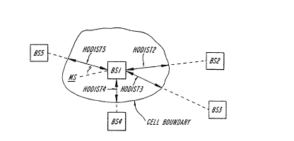
the cell. This can be seen with reference to Fig. 13, where HS1
is the current base station and.BS2 through BS5 represent
intracell neighbors. In Fig. 13, the cell size can be estimated
as the average of HODIST 2 through HODIST 5. Since the mobile
station could be anywhere in the region defined by the cell
boundary, a fraction of the average cell size should be used
according to the measured pathloss. This can be represented by
the following equation:
EIdTRYDIST = (k2 x pathloss) x AVEHOD3ST
where: AVEHODIST is the cell size estimate calculated by
averaging HODIST 1 through HODIST 5: and k2 is a constant which
scales down the cell size based on pathloss. The constant k~ is
determined in the same manner as kl.
In step 2~0 of Fig. Sb, when the new cell or channel is known to
share the same physical location as the old cell or channel, then
Wa 92/22~s6 PCT/SE92/OU403
the entry distance is already knawn from the current channel's
time alignment and no calculation is necessary. , The mobile
station in this case should be instructed to continue maintaining
the present timing offset following handoff. This method could
5 be used for the handoff case as presented by Figs. 5 and 6 when
the old time alignment value is available and intracell handoff
from a digital to a digital voiceJtraffic channel.
In Fig. 10A, at step 312, the entry distance can be estimated
using the following method according to a preferred embodiment of
10 the present invention. When a mobile station uses analog control
channels to setup a call, little is known about the position of
the mobile station within the accessed cell. However, the
pathloss of the mobile station measured during an access request
or paging response, can be used together with the average HODIST
15 value into the cell in a manner similar to the method described
with respect to Fig. 13 to estimate the entry distance. This can
be used, for example, in situations shown in fig. 2.
In Fig. 108, step 326, the time alignment parameter iTA can be
estimated as follows. Since it may be possible to directly
measure the timesync error of the mobile station access request
on a digital control channel, (see Fig. 7) the.variable iTA can
be calculated directly without reference to the entry distance or
call setup distance.
Fig. 14 is a block diagram of the functional elements of a
typical mobile station. The operating part 62 is controlled by
a microprocessor and is often incorporated in the handset 61.
The operating part 62 contains a push-button keypad and a display
of dial digits (not shown). The sensing of the pressed keys in
the operation of the display is handled by the above-mentioned
microprocessor.
The control part 64, which is also based on a microprocessor,
handles the following tasks. Control part 64 controls the data
signalling on the radio path according to conventional protocols.
Control part 64 also controls the radio part 65 to perform such
O
'WO 92/22966 PCT/SE92/OtD403
16
operations such as selection of channels, start of transmit,
opening of channel path, ete. Finally, the control part 64
controls communication with the operation paxt -62 as, for
example, during reception of the dialed telephone number to be
sent on the radio path. The control part 64 also controls the
scanning of the control channels broadcast by the closest base
stations to determine along which control channel communications
are to occur.
The radio part 64 consists of a transmitter, receiver and power
amplifier (not shown) and functions in a very similar way to the
corresponding parts described in the base station. The duplex
filter 66 is used for simultaneous transmission and reception via
the same antenna on the radio path. Additionally, a loud speaker
68 and microphone 70 can be installed for hands-free operation.
Figs. 15A and 155 are block diagrams illustrating an example of
a base station within a cellular mobile radio system. The base
station is designed for transmission and reception on a plurality
of radio channels used for digital communication channels, analog
communication channels and control channels. The equipment
configuration shown in Fig. 155, i.e. one control channel, a
number of voice channels, and one signal strength receiver, is a
typical configuration of a radio channel group required to serve
one cell. A typical base statian,shown in Fig. 15A comprises
three major functional units: a radio channel group 32, exchange
radio interface 30, and the power supply (not shown). The
exchange radio interface 30 functions as a medium to signal
between the mobile switching center and the base station. Thus,
the equipment receives data from the channel units and sends this
data to the mobile switching center on a dedicated mobile
switching center to base station data link. In the reverse
direction, the equipment receives data from the mobile switching
center on the mobile switching center to a station data link and
sends this data to the channel unit of destination. A voltage of
26.4 volts is normally provided as the distributed supply voltage
to the base station from mains via analog AC~DC converters. A
WO 92/22966 FaCT/SE92/00403
17
battery bac3c-up power supply is normally provided for continued
service in the case of mains breaDc down. . _
The radio channel group 32 holds all of the equipment normally
needed to handle the radio communication with the mobile
S stations. A typical radio channel group 32, shown in Fig. 15B,
comprises the following equipmenta channel units 42, 44, a
transmitter/combiner 46, receiver multi-couplers 48, a signal
strength receiver 50, a control channel redundancy switch 52, a
channel tester 54, a power monitoring unit 56 and an antenna
system 58.
The channel units for the control channels 42 and for the voice
channels 44 are identical. Each channel unit .consists of a
transmitter 440, a receiver 442 and a control unit 444 and a
power amplifier (not shown) connected to the transmitter output.
The output power determines the size of the coverage area of the
channel in question. The particular power amplifier used is
selected in order to obtain the required coverage for each cell.
In addition, accurate adjustment of the output power may ~be
manually performed.
A radio channel group can consist of a number of channel units,
for example, 96 channel units. A radio base station can consist
of one or more radio channel. groups.
In typical configurations, the racefiver multi-couplers 48 allow
a number of channel receivers and signal strength receivers to be
connected to the same receiver antenna. For example, up to 48
channel receivers and two signal strength receivers may be
connected to the same receiver antenna.
The signal strength receiver 50 is implemented in a channel unit
frame. It consists of a receiver 442 and a control unit 444.
The signal strength receiver 54 measures the strength of the
received signal (from the mobile stations) on any channel
allocated to the neighboring cells. The relevant channel numbers
as specified by the mobile switching center and the channels are
PCT/SE92/Oa443
dV0 92/22966 18
continuously scanned one-by-one and samples of the measurements
are stored in the control unit 444.
The transmitter combiner 46 allows a number of transmitters to be
connected to a common antenna, for example, up to 16 transmitters
can be connected to one antenna. The channel tester 54 performs
mobile switching center operator controlled tests of the
equipment. The power monitoring unit 56 is connected at the
combiner output. It supervises the forward and reflected power
and activates an alarm when, for example, the reflected power is
too high. The antenna system comprises several alternative
antenna configurations depending on the cell shapes required.
The control unit 444 used in the various channel units is based
on a microprocessor with program stores implemented. in the
read/write memories. In a preferred embodiment, the portions of
the method according to the present invention which occur in the
base station are implemented in the microprocessor. The
microprocessor can be any suitable commercially available
microprocessor. The control unit performs a large number, of
functions, a number of which are relevant to this invention and
are described herein. The remainder of the functions not
discussed herein are considered not relevant to the present
invention.
The control unit 444 controls the exchange of data messages
between the mobile switching center and the mobile stations.
2S Data to the mobile station is formatted with synchronization bits
and an error correction pattern and is inserted into the
transmitter. Data from the mobile station via the receiver 442
is detected and decoded and possible errors corrected prior to
sending it to the mobile switching center. The control unit 441
also evaluates the signal strength measured by the receiver 442.
Fig. 16 is a block diagram of an example of a mobile switching
center which can be used to implement the method according to the
present invention. The mobile switching center shown in Fig. 16
is a simplified block diagram of some of the functional units in
~ ~ c ~ a :~ Pc°r/sE92/oo~03
- WO 92/22965
19
a mobile switching center. Fig. 16 shows but cane example of a
mobile switching center. Other systems may also be used.
The mobile switching center 70 is a highly modular system which
includes a central processor ?2 and a mobile telephone subsystem
74 for the cellular system which is integrated with the other
subsystems. A group switching subsystem 78, a common channel
signalling subsystem 78, and a trunk and signalling subsystem 80
are connected to the central processor 72. The mobile telephone
subsystem 74 includes a regional processor 82, a mobile telephone
base station line terminal 84 and a signalling terminal 86. The
remaining subsystems also each include a regional processor 82.
The mobile telephone subsystem 74 handles all specific mobile
subscriber functions, cellular network functions, as well as the
signalling with the mobile stations. subsystem 74 also provides
the common channel signalling subsystem 78 with. the necessary
data from the mobile switching center signalling. The operation
and maintenance functions specific for the cellular system are
also implemented in the mobile telephone subsystem 74. The
mobile telephone subsystem 74 includes the mobile telephone base .
station line terminals 84 which connect the mobile telephone
subsystem 74 to the various base stations within the system and
to the public switching telephone network. The signalling
terminal 86 provided in the mobile telephone subsystem 74 handles
data communication between the mobile switching center and the
base stations. The regional processor 82 provided in each of the
subsystems stores and executes the regional software for the
switching system, handling simple, routine and high capacity
tasks.
The group switching subsystem 76 is controlled by a traffic
control subsystem (not shown). The group switching subsystem 76
sets up, supervises and clears connections through the group
switch (not shown). The common channel signalling subsystem 78
contains functions for signalling, routing, supervision and
correction of messages sent in accordance with a predetermined
~~d~~~ a
WO 92/229156 PCT/SE92/00403
standard. The trunk and signalling subsystem 80 supervises. the
state of the trunk lines to the public switching telephone
network and to the other mobile switching centers.y -_
The central processor 72 stores and executes the central
5 processor software for the switching system, handling the more
complex functions. These functions include, but are not limited
to, job administration, store handling, loading and changing of
programs, etc. The regional processor 82 in the mobile telephone
subsystem 74, in a preferred embodiment, implements those
10 portions of the method according to the present invention, which
occur in the mobile switching center. Alternatively, they may be
implemented in the central processor 72. The foregoing
description of the specific embodiments will so fully reveal the
general nature of the invention that others can, by applying
15 current knowledge, readily modify and/or adapt for various
applications such specific embodiments without departing from the
generic concept, and, therefore, such adaptations and modifica-
tions should and are intended to be comprehended within the
meaning and range of equivalents of the disclosed embodiments.
20 It is to be understood that the phraseology of terminology
employed herein is for the purpose of description and not of
limitation.