Note: Descriptions are shown in the official language in which they were submitted.
2089428
BACKGR011ND OF THE INVENTION
Field of the Invention
lQ The present invention relates to an apparatus and
method for wrapping articles.
~escription of the Related Art
Article wrapping devices are utilized for wrapping
articles with a protective wrapper, such as paper, plastic foil
or the like. Article wrapping devices are widely used in the
publ~shing industry to wrap bundles of signatures, such as
newspapers or magazines. Article wrapping devices have also been
used to package consumer products.
A conventional wrapping device which is widely used in
the publishing industxy is a three-sided bottom wrapper. Bundles
of signatures to be wrapped are conveyed on a series of generally
horizontal successive conveyor belts. A roll of wrapping paper
is positioned beneath the conveyor belts.
At a selected time, the roll feeds a leading edge of
the wrapping paper upward through a feed slot between two of the
successive conveyors. A mechanical gripping apparatus grips the
leading edge of the wrapping paper with a clamp, and lifts it
upward~ with a hydraulic or pneumatic cylinder. The wrapping
paper is thus lifted in an orientation which is generally
perpendicular to the path of the oncoming bundle of signatures.
When the bundle intersects the wrapping paper, the leading edge
of the wrapping paper is released by the clamp, and drapes over a
top side of the bundle. Simultaneously, a cutting device below
the conveyors slices the dispensed wrapping paper from the roll.
~he trailing end of the dispensed wrapping paper is dragged
beneath the bundle by its continued passage on the conveyor belts
past the feed slot.
The mechanical gripping apparatus used to lift the
sheet of wrapping material significantly increases the unit cost
of the article wrapping device.
Maintaining and replacing such a mechanical gripping
apparatus is costly and can result in unacceptable down time for
: :
- - : ~ .
2089428
the entire article wrapping device while the mechanical gripping
device is maintained or overhauled.
- The mechanical gripping apparatus also slows the
throughput rate of the wrapping device. When a bundle has been
wrapped and is exiting the device, the mechanical gripping
apparatus must be lowered to grip the next sheet of wrapping
paper to ~rap the next bundle. This creates ~dead time~ in the
cycle, because no follow-on bundle can be wrapped until the
mechanical gripping apparatus is lowered and grips the next sheet
of wrapping paper. Throughput of the wrapping device is thus
inhe~ently limited by the operation of the mechanical gripping
apparatus.
It is an object of the present invention to provide a
simple and reliable article wrapping device which does not
require a mechanical gripping apparatus to grip the leading edge
of the wrapping paper. Deletion of the mechanical gripping
apparatus will minimize maintenance, eliminate a source of
potential failure, and minimize the overall cost and down-time of
the article wrapping device.
It is also an ob~ect to provide for increased
throughput of the wrapping device, by eliminating the "dead time~
! associated with the operation of the mechanical gripping
apparatus, and allowing a follow-on bundle to enter the device
before the previous bundle has exited the device.
Additional objects and advantages of the invention will
be set forth in the description which follows, and in part will
be obvious from the description, or may be learned by practice of
the invention. The ob~ects and advantages of the invention may
be realized and obtained by means of the instrumentalities and
combinations particularly pointed out in the appended claims.
SUMMARY OF THE INVENTION
I ~o achieve the foregoing ob~ects, and in accordance
`~ with the purposes of the invention as embodied and broadly
described herein; an article wrapping device comprises conveyor
` means for conveying articles to be wrapped along a first path in
a generally horizontal direction, feeding means beneath the first
path~for feeding a sheet of wrapping material upwards along a
.
:,,,,~.
. . . . .
. .
-. :: '
;~ , . ~ : '' ~.
.~ , - - -
2089~28
-- 3 --
second path in a generally vertical direction, the second path
intersecting the first path, displaceable wall means disposed in
a generally vertical orientation across the first path alongside
the second path above the feeding means, and air flow means for
providing a flow of air along and between the second path and the
displaceable wall means to maintain a general orientation of the
sheet of wrapping material in the second path.
It is preferable that the article wrapping device
further comprise means for dampening oscillatory movement of the
displaceable wall means follo~ing displacement by the article,
thereby allowing the displaceable wall means to be quickly
repositioned in the generally vertical orientation following
displacement of the displaceable wall means by the article.
It is also preferable that the displaceable wall means
comprises a flexible curtain supported from a location above the
first path.
BRIEF DESCRIPTION OF THE DRAWINGS
The accompanying drawings, which are incorporated in
and constitute part of the specification, illustrate a preferred
embodiment of the invention and, together with the general
description given above, and the detailed description of the
preferred embodiment given below, serve to explain the principles
of the invention.
FIG. 1 is a partial side view of a preferréd embodiment
of an article wrapping device according to the teachings of the
present invention;
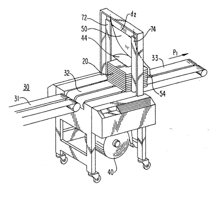
FIG. 2 is a perspective view of the article wrapping
device depicted in Fig. 1;
FIG. 3 is a representative side view depicting the
displaceable wall means and repositioning means of the device
depicted in Fig. l;
FIGS. 4-7 are perspective views of the device of Fig.
1, showing a sequence of operational steps;
DESCRIPTION OF THE PREFERRED EMBODIMENT
Reference will now be made in detail to the present
preferred embodiment of the invention as illustrated in the
accompanying drawings.
-
- '
. . .... ... :, . . ~ . ,
.
. : , ~ :
: ::
` 2089428
-- 4 --
According to the present invention, an article wrapping
device includes conveyor means for conveying articles to be
wrapped along a first path in a generally horizontal direction.
As embodied in Figs. l and 2, an article to be wrapped 20, which
may be bundle of signatures, is conveyed in a generally
horizontal first path P1, on conveyor 30.
Preferably, conveyor 30 includes a plurality of
successive con~eyor portions 31, 32, 33. As embodied in Figs. 1
and 2, conveyor portions 31, 32, 33, consist of pairs of
successive conveyor belts, rotating on respective sets pulleys
34, 35, 36. However, conveyor 30 is not limited to successive
pairs of conveyor belts. Conveyor 30 may include successive
chains, rollers, or any of the like devices that are well known
in the conveyor art.
According to the present invention, the article
wrapping device includes feeding means beneath the first path for
feeding a sheet of wrapping material upwards along a second path
in a generally vertical direction, the second path intersecting
the first path. As embodied in Fig. l, a roll of wrapping
material 40, which may be a roll of kraft paper, is rotatably
mounted beneath conveyor 30 on axle 41. A sheet of wrapping
material 44 is fed via pulley 45 between nip rolls 46, also
disposed beneath conveyor 30, in a generally vertical second path
P2.
Preferably, the sheet of wrapping material 44 is fed
through a slot 48 between two of the successive conveyor
portions. As embodied in Fig. l, slot 48 is positioned between
conveyor portions 32, 33. As sheet of wrapping material 44
penetrates slot 48, it intersects first path P1.
According to the invention, the article wrapping device
includes displaceable wall means disposed in a generally vertical
orientation across the first path alongside the second path above
the feeding means. As embodied in Fig. 1, displaceable wall 50
depends from a bracket 52 suspended above conveyor 30.
Displaceable wall 50 hangs in a generally vertical direction,
spaced a short distance dl from the second path P2 of sheet of
wrapping material 44.
2~89~28
- 5 -
As embodied in Fig. l, roll 40, nip rolls 46, and slot
48 are positioned relati~e to displaceable wall 50 so that sheet
of wrapping material 44 is fed between the article to be wrapped
20 and displaceable wall 50. In this embodiment, a single
displaceable wall 50 is positioned downstream of sheet of
wrapping material 44 as it is fed in second path P2.
Alternatively, it is within the scope of the invention to provide
one displaceable wall upstream of sheet of wrapping material 44,
and another displaceable wall downstream of sheet of wrapping
material 44.
Preferably, displaceable wall 50 comprises a flexible
plastic curtain suspended from bracket 52. It is further
preferable that the flexible curtain include a weighted lower
edge portion. As embodied in Fig. 1, a rigid rod 54 is attached
at lower edge 55 of the curtain. In the embodiment where
~isplaceable wall 50 comprises a flexible curtain, rod 54
flmctions as a weight which applies tension to the curtain,
thereby helping to maintain displaceable wall 50 in its generally
vertical orien~ation.
According to the invention, the article wrapping device
includes air flow means ~or providing a flow of air along and
between the second path and the displaceable wall means to
maintain a general orientation of the sheet of wrapping material
in the second path. As embodied in Fig. 1, a pressurized air
source 60 is provided beneath conveyor 60. Pressurized air
source 60 may include one or a plurality of air jets 62,
including a pressure regulator 64 and a nozzle 66.
Preferably, each nozzle 66 is positioned to direct a
flow of forced air in an upward direction generally along third
path P3 through slot 48. According to the invention, third path
P3 will he between the sheet of wrapping material 44 travelling
in second path P2 and the displaceable wall 50.
In this configuration, the flow of forced air enables
the article wrapping device to operate without the use of a
mechanical gripping apparatus to lift the sheet of wrapping
~aterial 44. Sheet of wrapping material 44 will be drawn
slightly toward displaceable wall 50 but will remain spaced from
. ' . ' -
:
2089~28
-- 6 --
displaceable wall 50. This attraction towards displaceable wall
50 enables sheet of wrapping material 44 to maintain its
generally vertical orientation, as it continues to be fed upward,
without the use of a mechanical gripping apparatus.
According to the invention, the article wrapping device
further includes means for dampening oscillatory movement of the
di~placeable wall means after being displaced by the article, to
assume its original generally vertical orientation. As embodied
in Figs. 2 and 3, wall stopper 70 includes a pair of bars 72, 74,
disposed alongside each side of conveyor 30. Bars 72, 74 are
positioned in alignment with one another, and spaced apart by a
distance d2. Preferably, distance d2 is less than the width of
displaceable wall 50. Bars 72, 74 each have a height which is
slightly less than the height of displaceable wall 50.
Although not shown or numbered, the article wrapping
device further includes means for sensing the article 20 on
conveyor 30, and means for cutting sheet of wrapping material 44
from the roll of wrapping material 40. Such means are well known
25 in the article wrapping device art, and will not be discussed `
further.
An operation of the article wrapping device according
to the present invention will now be described. This operation
i8 described with reference to Fig. 1, and more particularly to
; 30 Figs. 4-7.
As shown in Fig. 4, article 20, for example a bundle of
signatures, is fed to an infeed location on conveyor 30, where it
is conveyed in a generally horizontal direction along first path
Pl on successive conveyor portions 31, 32, 33. ~isplaceable wall
50, suspended from bracket 52 above the first path, is oriented
in a generally vertical direction intersecting the first path P1.
~`~ At a preselected position of article 20 along first
path Pl, an article sensor (not shown) detects the presence of
article 20 and instructs wrapping material roll 40 to commence
feeding~a sheet of wrapping material 44 about pulley 45 and
between nip rolls 46 tnot shown in Fig. 4). Sheet of wrapping
~material 44 is fed in a generally vertical direction in a second
pa~th P2. Second path P2 intersects first path Pl, and is
.~
;
. , .
2089~28
- 7 -
s
generally perpendicular to first path Pl. As it is fed along
second path P2, sheet of wrapping material 44 passes through slot
48, and continues upward alongside displaceable wall 50,
approxi~ately a distance d1 from displaceable wall 50.
As sheet of wrapping material 44 passes through slot
48, air jets 62 (not shown in Fig. 4) disposed beneath conveyor
30 are energized. Air jets 62 blow forced air upward through
slot 48, between the second path P2 and the displaceable wall 50.
Referring now to Fig. 5, article 20 continues to be
conveyed along first path Pl. Sheet of wrapping material 44 has
been fed farther along second path P2. ~he flow of forced air
from air ~ets 62 between the sheet of wrapping material 44 and
displaceable wall 50 creates a low pressure area between the
sheet of wrapping material 44 and displaceable wall 50. The
sheet of wrapping material 44 is slightly attracted towards
displaceable wall 50, enabling sheet of wrapping material 44 to
maintain its generally vertical orientation.
Referring now to Fig. 6, article 20 continues along
first path Pl, intersecting sheet of wrapping material 44, and
next intersecting displaceable wall 50. Displaceable wall 50 is
displaced in the direction of the first path Pl. As can be seen
from Fig. 6, displaceable wall 50, as it is displaced, functions
to force a leading edge of the sheet of wrapping material 44 over
a top side of article 20. At approximately this timé, feed roll
40 stops rotating, and cutting means (not shown) beneath conveyor
30 cut a trailing edge of the sheet of wrapping material 44 from
roll 40. At this time, air ~ets 42 can be deenergized.
Referring now to Fig. 7, article 20 continues to be
conveyed in first path P1. Rod 54 on the trailing edge of
displaceable wall 50 passes across the top side of article 20,
ensuring the leading edge of sheet of wrapping material 44 is
wrapped over the top side. Meanwhile, the trailing edge of sheet
of wrapping material 44 wraps around a bottom side of article 20
~;~ 40 by the friction of conveyor portion 33, as article 20 continues
`~ ~ in the first path Pl .
Shortly after the position shown in Fig. 7, the
~; trailing edge 55 of displaceable wall 50 passes over the top side
., .
: .
.
.
-. . .
. . : . . .
'.
2089~28
of article 20. Displaceable wall 50 now swings back toward its
generally vertical orientation shown in Fig. 4. It will be
xeadily understood that without the presence of the dampening
means, wall 50 would oscillate for several seconds before
regaining its vertical orientation. This would cause a delay
before another article could be converged along first path Pl.
However, in accordance with the invention, as displaceable wall
50 swings (see Fig. 3), it is quickly repositioned in its
l$ generally vertical orientation when bar 54 hits bars 72, 74 and
the side portions of the curtain come in contact with bars 72 and
74, preventing a wave from oscillating along the length of the
curtain. By preventing this oscillation, displaceable wall 50
quickly returns to its original generally vertical orientation,
thereby enabling another article 20 to be conveyed along first
path P1 in a relatively short period of time.
In the device described above, an article being
conveyed on a conveyor in a generally horizontal direction is
wrapped by a sheet of wrapping material fed upward from beneath
the conveyor. No mechanical gripping apparatus is required to
lift the sheet of wrapping material upwards, because the sheet of
wrapping material can be maintained in a generally vertical
orientation without re~uiring such a mechanical gripper.
~limination of the mechanical gripping apparatus simplifies the
overall design. The need for maintenance and overhaul of the
mechanical gripping apparatus is eliminated. Costs and down-time
for the entire article wrapping device are significantly reduced.
Furthermore, follow-on bundles can be fed to be wrapped
without the "dead time" associated with a mechanical gripping
apparatus being lowered to grip the next sheet of wrapping
material. Therefore, the throughput rate of the device is
increased.
Additional advantages and modifications will readily
occur to those skilled in the art. The invention in its broader
aspects is therefore not limited to the specific details and
representative apparatus shown and described. Accordingly,
departures may be made from such details without departing from
the spirit or scope of the applicant~s general inventive concept.