Note: Descriptions are shown in the official language in which they were submitted.
2 ~ 3
VACUU~_CLEANING TOOI. FOR WET AND DRY VACUUM CLEANERS
The invention refers to a vacuum cleaning tool
according to claim 1.
Wet cleaning is inevitable particularly for cleaning
textile floor coverings. Initially the coarse dust is
cleaned off and this is preferably carried out with a brush
roller which ro-tates in a flow of vacuum air. Then cleaning
foam is applied and the floor covering is cleaned
mechanically - preferably by just a rotating brush. Excess
10 fluid must then be vacuumed off so that when the floor
covering is dry it can be vacuumed again, perhaps with
brushes.
A vacuum cleaning tool is used for dry vacuuming and
already exists, for example, according to the US patent
15 4,426,751. Two brush rollers rotating in opposite
directions are located in a brush chamber and a vacuum air
duct is provided on a tangent to each. Both vacuum air
ducts open into a common connection which leads to a vacuum
cleaning unit.
The German patent DE 34 14 860 ~1 shows that the flow
of turbine air driving the brush roller can be adjusted by a
flow flap.
For wet cleaning, in particular for vacuuming off any
excess cleaning fluid, a vacuum cleaning tool which has been
25 suitably adapted must be used. For this reason the vacuum
cleaning tool has to be replaced for this procedure. This
~9~3
is complicated and time--consuming, especially if only
individual parts of a large overall area are to be cleaned
one after the other.
The invention is based on the task of providing a
vacuum cleaning tool of the type stated at the outset but
which can carry out the dry and we-t vacuuming processes
without the vacuum cleaning tool having to be changed.
This task is solved by the invention according to the
main characteristics of claim 1.
The wet vacuuming duct formed in particular between a
cover part fixed to the casing and the top part of the
casing itself connects a wet vacuuming opening provided at
the base of the casing to the connection for the vacuuming
cleaning tool so that the vacuum opening, the brush chamber
and the flow duct to the connection - and therefore also the
turbine chamber - are bypassed. This therefore provides a
separate flow path for wet vacuuming and avoids any effect
on the ducts for dry vacuuming. ~ flow blocking device is
provided in the wet vacuuming duct as well as in the flow
2n duct so that the one or other duct can be operated
individually. The flow blocking device completely closes
off the duct which is not required, so that no unwanted air
flow - whether dry or wet - occurs
An air duct which opens into the turbine chamber
25 parallel to the flow duct is beneficial and is fitted with a
switchable flow blocking device so that in the dry mode
2 ~ 3
either a flow of vacuum air with the rotating brush is
available or just the rota-ting brush itself. A vacuum
cleaning tool of such a design can be used in three totally
independent modes of operation, i.e. brushing with a vacuum
flow of air (flow duct open), brushing without a vacuum flow
(auxiliary air duct open) and wet vacuuming ~wet vacuum duct
open).
The flow blocking devices are connected in relative
positions by a linking device to ensure that when one of the
10 ducts is open the other ducts are closed. Such a linking
device should ideally possess a control cam which holds the
free end of the actuator arm of tlle relevant flow blocking
deviee which is designed as flap. The eams are designed and
physically located according to the switching positions
15 required.
The part of the cover which together with the top part
of the casing forms the wet vacuuming duct should ideally be
clipped to the casing of the vacuum eleaning tool. In this
way the cover part can easily be replaced by a plate which
20 covers only the overflow opening of the wet vacuum duet and
the overflow opening of the au~iliary air duct at the top of
the easing.
Further features of the invention are shown in the
other elaims. The invention is illustrated in the drawings
25 with a design e~ample which is described in detail below.
The drawings show:
- - ~
Fig. 1 Top view of the upper section of the casing of a
vacuum cleaning tool
Fig. 2 Section along the line A-A in Fig. 1
Fig. 3 Section along the line B-B in Fig 1
Fig. 4 View from below of the top section of the casing
according to Fig. 1
Fig. 5 Section along the line C-C in Fig 1
Fig. 6 View of the underside of the bottom part of the
casing of the vacuum cleaning tool
10 Fig. 7 Section along the line D-D in Fig. 6
Fig. 8 Top view of a turbine chamber casing with an
integral connection
Fig. 9 Section through the turbine chamber casing along
line E-E in Fig. 10
15 Fig. 10 Axial section through the turbine casing according
to Fig. 8
Fig. 11 Section through the vacuum cleaning tool at the
level of the flow duct
Fig. 12 section through the vacuum cleaning tool at the
~0 level of the flow duct in a further design
Fig. 13 Section through the vacuum cleaning tool at the
level of the wet vacuum duct
; Fig. 14 Schematic representation of a link component
designed as a switching gate
25 Fig. 15 Relevant design of the linking component according
to ~ig. 14
2 ~
Fig. 16 View of the linking component according to Fig. 15
Fig. 17 Top view of a cover for forming the wet vacuum
duct
Fig. 18 View of the cover from below
Fig. 19 View of the cover from behind
Fig. 20 Section through the cover along the line F--F in
Fig. 17
Fig. 21 Section along the line G-G in Fig. 17
Fig. 22 View of an air turbine with a bearing on one side
Fig. 23 Axial view of the air turbine according -to Fig. 22
Fig. 24 Top view of a cover plate
Fig. 25 Section through the cover plate according to the
line H-H in Fig. 24
Fig. 26 View from below of the cover plate according to
Fig. 24
The vacuum cleaning tool shown in the drawings has a
casing which consists of a top section (1) (Fig. 1) and a
preferably hinged bottom section (2)(Fig. 6). The top
section o~ the casing (1) shown in a top view in Fig. 1 is
generally rectangular, whereby the one long side forms the
front face (3) of the vacuum cleaning tool and the other
long side orms the rear (4) of the tool. A mounting (6) is
provided in the top part of the casing (1) symmetrical to
the lateral centre axis (~) and is largely open upwards and
to the rear (4) of the vacuum cleaning tool. The mounting
(6) serves for installing a turbine chamber casing (3) as
~~
2 ~ 3
shown in Figs. 8 to 10. It mainly consists of a half
cylinder (31) which is sealed at its axial ends by walls
(32). On the side opposite the opening (33) the half
cylinder is connected to a funnel section (34) which becomes
a connection (35) for the vacuum hose of a vacuum cleaning
unit not shown in more detail. The side wa-lls (32) of -the
turbine chamber casing (30) are rounded on the edge (36)
towards the opening (33), whereby a step (37) is provided at
the changeover to the base section (31a) of the half
cylinder (31). This step (37) acts together with a stop
(79) on the casing (Fig. 11) in limiting the pivoting
movement of the turbine chamber casing (30) in the mounting
(6). In the direction of the longitudinal centre axis (38)
there is a slot (32a) in each side wall (32) and each slot
15 ends in a semicircle t32b)(Fig. 9). The centre point of the
semicircle (32b) lies on the centre axis (39) of the half
cylinder (31) which at the same time represents the axis of
rotation of the turbine chamber casing (30) in the top
section of the casing (1) and also the axis of rotation of
an air turbine provided in the turbine chamber casing.
When viewed from above, the front long edge (33a) of
the base of the half cylinder (31a) lies in front of the
long edge (33b) of the part of the cylinder (31b) which
forms the roof. The opening (33) which is limited by the
long edges (33 and 33b) and by the edges (36) of the side
walls (32) is of a height approximately equal to the
2~g~
diameter of the half cylinder (31) and is divided into a
large inlet opening (41) and a small inlet opening (42) by a
partition (40) provided at right angles to the centre axis
(39). The large inlet (41) opens into the actual turbine
chamber (43) which is limited by the one axial side wall
(32) and the partition (40). The small inlet (42) forms a
bypass duct (44) for the turbine chamber (43) whose function
is explained in detail in the following section.
In the area of the connection of the funnel section
(34) and the axial side walls (32) there are mountings (45a)
for securing screws or bolts which are not shown in more
detail.
The turbine chamber casing (30) which can pivot around
the axis (39~ in the mounting (6) has ducts in the top part
of the casing (1). As shown in section A-A in Fig. 1, the
opening (42) of the kurbine chamber casing (30) fitted in
the mounting (6) lies opposite an overflow opening (45)
whlch is separa-ted from the overflow opening (47) by a
partition (46). The overflow openings (45 and 47) lie on
the top part of the casing towards the front ~ace (3), as
shown in particular by Figs. 2 and 3. The partition (46)
protrudes with an extension (48) towards the half
cylindrical mounting (6) into the mounting (6) so that the
partition (40) of the turbine chamber casing (30) when
; 25 fitted and the extension (48) overlap when viewed in the
axial direction.
~ 2 ~
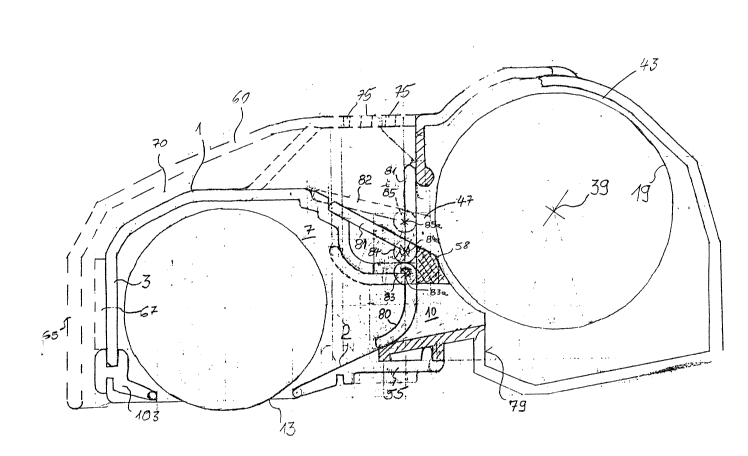
A flow duct (10)(Fig. 3) which starts from the brush
chamber (7) and opens into the mounting (6) is provided
below the overflow opening (47). As shown in Fig. 3, a
vertical slot (49) is provided in the partition (46) and
begins above the flow duct (10) and continues approximately
to the bottom edge of the overflow opening (45). The slot
(49) serves to support the activator shafts (83, 84, 85) for
the flow blocking devices (80, 81 and 82)(Fig. 11) which are
described in more detail below.
Parallel to the walls (6a and 6b) of the mounting (6)
the casing construction (7a) in which the mounting (6) is
provided is provided with grooves (B and 9) parallel to the
lateral centre axis (5). Latching openings (11 and lla
respectively) are provided in the base of these grooves.
the design of the casing (7a) is symmetrical to the lateral
centre axis (5).
; In the base (16) of the mounting (6) which lies at a
sharp angle of approximately 15 to the hori~ontal there are
slots (15) on both sides of the lateral centre axis (5).
The slots lie adjacent to the axis of rotation (39).
On the one side of the lateral centre axis (5) an
opening is provided next to the casing (7a). A largely
rectangular rocker switch (12a) is located in this opening.
The rocker switch (12a) is fitted so -that it can swivel
around the axis (39) and has three positions which are
described individually below.
21~9~
The bottom view illustrated in Fig. 4 shows the brush
chamber (7) which at its axial ends has mountings (12) to
support a rotating brush roller (13). This roller (13) is
fitted with a belt pulley (14) at one end which is driven by
a belt, preferably a toothed belt (17), by a drive pulley
(18). The drive pulley (18) rotates around the centre axis
(39) and is driven by the drive shaft (21) of an air turbine
(19), whereby one end of the drive shaft (21) is located in
a hollow shaft (20) mounted in the casing. The axis of
rotation of the air turbine (19) corresponds to the centre
axis (39).
The base (16) of the top part of the casing (1)
protrudes beyond the rear (4). In the corner be~ween the
base (16) and the rear (4~ there is a casing (29) in which a
rotor (not shown) is fitted so that it can rotate.
The bottom section of the casing shown in Figs. 6 and 7
is secured in the top part of the casing (1) by means of
screw domes (50) in the bottom part of the casing (4) into
which securing bolts which pass through openings (51) in the
; 20 bottom part of the casing (2) are fitted. The bottom part
of the casing (2) is generally U-shaped when viewed from
above, whereby the two legs (52) cover the top part of the
casiny at the side of tha base (16). A vacuum opening (53)
is provided in the bottom part of the casing (2) which forms
the base and this opening lies at right angles to the
lateral central axis (5), generally stretching over the
2 ~
-- 10 --
entire width of the vacuum cleaning tool. The bristl~s of
the brush roller (13) protrude through the vacuum opening
(53) as shown schematically in Figs. 11 to 13. A U-shaped
mounting (54) is provided on both of the narrow edges of the
bottom part of the casing (2) approximately at the level of
the shoulders in the legs (52) and these mountings (54)
serve to support the other rotating rollers (not shown)
which are fitted at the base of the vacuum cleaning tool.
Between the two legs (52) is an extension (55) which, as
10 shown in Fig. 11, extends below the flow duct (10). This
therefore guarantees to provide a tight seal between the
bottom part of the casing (2) and the top part of the casing
(1) in the area of the flow duct (10). It can be beneficial
to fit a rubber seal (103) between the bottom edge of the
15 front face (3) of the top section of the casing (1) and the
edge of the bottom section of the casing (2). The
cross-section of the edge of the casing should be designed
to fit the rubber seal (103).
~; As shown in the section according to Fig. 7 the legs
(52) are fitted with clips (56) on the side towards the
bottom part of the casing (2). As described below, these
clips (56) fit around the shafts (20) installed on both
sides of the mounting (6) in the top part of the casing (1)
and are therefore held firmly to them. The clips (56) are
25 shown in Fig. 6. Bearing covers (57)(Fig. 7) are also
provided at the axial ends of the bottom part of the casing
,. . .
2 ~
(2) to close the mountings (12) in the top part of the
casing tl).
Figs. 11 to 13 show various sections through the vacuum
cleaning tool according to the invention, parallel to the
S lateral centre axis t5). On the top part of the casing tl)
a hood-shaped cover t 60) is secured which is approximately
T-shaped in its top view (Figs. 17 and 18). The foot of the
"T" is angled, as shown in Figs. 20 and 21.
The hood-shaped cover section t60) has a connecting
area t62) whose width is slightly broader than the mounting
t6) and has lugs t61) at the side of its free end (63) which
are designed as extensions of the side walls t64). The side
walls are designed to fit in the grooves t8 and 9) in the
top section of the casing (Fig. 1) whereby the front lugs
(61) reach into the openings (11) next to the centre axis
(39). As Figs. 20 and 21 show, the side walls have further
lugs (6la) which are provided to reach into the openings
(lla)(Fig. 1). The hood-shaped section (62) there~ore lies
firmly on the top part of the casing (1) and thus forms the
wet vacuum duct (7) running from the mounting (6) to the
front face (3). This connects a wet vacuum opening (71)
located at the level (59) of the vacuum opening (53) in
front of the front face (3) with the overflow opening (45)
to the mounting (6). The wet vacuum opening t71) is limited
by the bottom edge of the front face (3) and the bottom edge
of a vertical wall (65) lying at the level (59) of the
2~9~
- 12 -
vacuum opening (53), whereby the vertical wall ~65) changes
into the connection area (62). At its end opposite the
vertical wall (65) this connection area (62) extends with a
roof section (66) over the mounting (6) and ends - when
viewed from the top - just in front of the common axis of
rotation (39).
The wet vacuum opening (71) connects to a funnel
section (72)(Fig 19) which is provided between an inner wall
(67) and the outer wall (65). The funnel section (72), as
part of the wet vacuum duct (70), reduces the cross-section
available for the flow of air to the passage in the
connection area (62) which corresponds approximately to the
width of the mounting (6). As shown by the bottom view
according to Fig. 18 a Z-shaped seal wall (68) is provided
lS in the connection area (62), approximately at right angles
to the lateral centre axis (5). The seal wall (68) is
designed as a double wall, for installing a rubber seal.
The seal wall (68) lies ln contact with the upper side of
the casing (1) which produces an area (69) separate from the
wet vacuum duct (70). This area (69) is connected to the
overflow opening (47). As Fig. 17 shows, several openings
(75) ~or auxiliary air are provided in the area (69) in the
roof of the connection area (62) and allow air from the
environment to enter when the overflow opening (47) is open.
Figs. 11 to 13 show that a flow blocking device is
fitted in the duct (10) from the brush chamber ~7) to -the
. -;
2 ~
- 13 -
turbine chamber (43). The blocking device in the design
example shown is a flap (80). In the same way, a flow
blocking device in the form of a flap (81) is provided for
the overflow opening (47). Similarly, the overflow opening
(45)(Fig. 13) can also be closed by a blocking device in the
form of a flap (82). The blocking devices preferably
designed as flaps (80 to 82) are each firmly connected to an
actuator shaft (83 to 85) which is held parallel to -the
centre axis or the axis of rotation (39) in the top part of
the casing. The three actuator shafts (83, 84 and 85) are
fitted reasonably tightly in a slot (8~) in the separating
wall (46). The closeness of the actuator shaEts (83 and 84)
forms a type of partition which separates the overflow
opening (47)(Fig. 11) fxom the flow duct (10). The part of
the casing (58) shaded in Fig. 11 can -therefore be dispensed
with since its separating function is taken over by the two
adjacent actuator shaf-ts (83 and 84).
The ends of the actuator shafts (83 to 85) towards the
roc~er switch (12a) each have an arm (87, 88 and
89)(Fig. 14) whose free ends (87a, 88a and 89a) reach into
the control cams (90 and 91). For this, the free ends (87a
and 88a) of the axms (87 and 88) reach into a common
U-shaped control cam (90), whilst the free end (89a) of the
arm (89) reaches into a separate V-shaped control cam (91).
The cams (90 and 91) are provided in a cam disc (92) which
can pivot around its a~is of rotation (39). The V-shaped
2 ~
- 14 -
cam (91) lies with the opening of the "V" towards the axis
of rotation (39). The opening of the "U" in the U-shaped
cam (90) lies away from the axis of rotation (39). The cam
disc (92) shown as a component in Fig. lS links -the settings
of the flaps (80 to 82) according to the shape of the cams
(90 and 91) and the cam disc (92) therefore acts as a link
for the flaps (80 to 82).
As shown in Fig. 16 the cam disc (92) is strengthened
by ridges (93 and 94) so that the rocker switch (12a)
protruding out of the top part of the casing can be screwed
firmly to the connecting component (9S). When the rocker
switch (12a) is operated - by foot, for example - the cam
disc (92) is pivoted from the centre position shown in Fig.
14 either in the direction of the arrow (96) or the arrow
(97)-
The configuration is such that when the rocker switch(12a) is in the centre position the cam disc (92) is in the
position according to Fig. 14 in which the free end (89a) o~
; the actuator arm (89( lies at the neutral low point of the
V-shaped cam (91) and the free ends (87a and 88a) of the
actuator arms (87 and 88) lie in the neutral area of the rib
on the U-shaped cam (90).
Whilst at the neutral point of the cam (91) the flap
(82) takes on the rest position shown in Fig. 13 in which
the overflow opening (45) is clear, the flaps (80 and
81)(Fig. 11) lie in their working position where the flow
duct (10) or the overflow opening (47) respectively is
closed. To compensate for measurement tolerances in the
closed position the flap (80) can be bevelled at its outside
end.
5With the flap (82) in the wet vacuum duct (70) in the
rest position as shown, the flap lies in a recess (73) in
the top section of the casing (1) so -that the open flap (82)
does not restrict the flow. The recess (73) is also shown
in Fig. 2.
10If the cam disc (92) is moved in the direction of the
arrow (97) by pressing the rocker switch (12a), the free end
(89a) of the lever (89) moves into the end point (9la) of
the leg on the V-shaped cam wherehy the actuator shaft (85)
rotates and the flap (82) moves to the working position
shown in Fig. 13 in which the overflow opening (45) is
sealed. As a further feature, a stem (106)(Fig. 21) is
provided in the cover section (60) against which the flap
~82) rests in its operating position and this determines the
closed position. The closing movement of the flap (82) is
linked to the movement of the ~ree end (88a) of the actuator
arm (88) into the end of the leg (9Oa~ of the U-shaped cam
(90), which moves the actuator shaft (84) and opens the
overflow opening (47)(Figs. 11 and 12). A recess (74)
corresponding to the recess (73) is provided in the top part
of the casing (1) to accept the flap (81) in its rest
position. The free end (87a) of the actuator arm (87) only
2 ~
- 16 -
moves in the neutral area of the cam (90), so that the
actuator shaft (83) does not rotate.
If the rocker switch (12a) is moved in the direction of
the arrow (96) the free end (89a~ of the actuator arm (89)
moves into the end point (9lB) of the leg and the flap (82)
closes the overflow opening (45) again and the wet vacuum
duct is therefore blocked. This movement is linked to the
movement of the free end (87a) of the actuator arm (87) into
the end of the leg (9Ob) of the cam (90), which rotates the
actuator shaft (83) and therefore opens the flow duc-t (10).
In order to avoid any restriction in the flow the flap (80)
is curved and therefore lies flush against the curved wall
of the brush chamber. The free end (88a) of the actuator
arm (88) stays in the neutral area of the cam (90) so that
the overflow opening (47) remains closed.
The linking component (95) is connected ~irmly to a
collar (98), and is preferably o~ a one-piece design with
the collar (98). Latching openings (99a to 99c) are
provided in the jacket of the collar into which a
spring-loaded ball (100) held in the casing is pressed.
When the ball (100) latches into the opening (99b) this
secures the centre position of the rocker switch (12a)
corresponding to the position of the cam disc (92) in Fig.
14. In this position a mi~ture of air and fluid flows into
the vacuum cleaning tool only through the wet vacuum opening
(71), is fed -through the wet vacuum duct (70) past the brush
2 9 ~
- 17 -
chamber (7) and the duct (10) to the overflow opening (45)
and then enters the bypass duct (44) of the turbine chamber
casing. The bypass duct (44) bypasses the turbine chamber
(43) so that -the mixture of air and fluid flows directly out
through the connection (35).
When the ball (100) is latched into the opening (~9a)
the flap (82) closes off the wet vacuum duct (70) while the
overflow opening (47) is open, so that air flows only
through the auxiliary air openings (75) and the auxiliary
air duct to the turbine chamber (43). This drives the air
turbine (19) so that the brush roller (13) rotates. The
vacuum cleaning tool can be used for brushing. If the ball
(100) is latched into the opening (99c), the wet vacuum duct
(70) is closed, the auxiliary air opening (47) is closed and
; 15 now the duct (10) is open so that the brush roller (13) can
rotate as normal, the dissolved dirt enters the brush
chamber (7) thLough the vacuum opening (53) and is fed out
through the duct (10), the turbine chamber (43) and the
connection (35).
The position of the mouth of the duct (10) into the
turbine chamber (43), the auxiliary air duct (47) into the
turbine chamber and the changeover from the wet vacuum duct
(70) to the bypass duct (44) is guaranteed whatever the
position of the turbine chamber casing (30) around the axis
25 of rotation ~39), as the turbine chamber is open through an
angle of 180~ around its circumference. The air turbine
2 ~
- 18 -
(19) fitted in the turbine chamber (43) is connected on one
side to the drive shaft (21) which protrudes through the
hollow shaft (20). The drive shaft (21) is located in the
hollow shaft (20) and carries at i-ts free end (22)
protruding out of the hollow shaft (20) a drive belt pulley
(18) which is preferably designed as a toothed belt pulley.
The hollow shaft (20) at its end towards the air
turbine (19) is fitted with a bearing section (23) which is
held in the side wall (6a) of the mounting (6)(Fig. 1) so
that it can rotate. The bearing section (23) has a holding
flange (24) which is designed to match the slot (32a) in the
side wall (32) of the turbine chamber casing (30). In the
same way, a shaft is fitted in the side wall (6a) of the
mounting (6) adjacent to the rocker switch (12a) so that the
shaft can rotate around its cent:re axis (39). A support
flange (not shown) fits into the slot (32a) on the other
side of the turbine chamber cacsing (30). Opposite the
support flange (24) and offset to the side is a screw flange
(25) which - as shown by the broken line in Fig. 10 - lies
opposite the screw mounting (45a) and is intended for a
securing bolt to firmly connect the turbine chamber casing
(30) to the top section of the casing (1).
On the end away from the drive shaft (21) lies the air
turbine - as indicated in Fig. 4 ~ adjacent to the partition
(40)(Fig. 10). The air turbine (19) consists of a centre
disc (107) which is fit-ted on both sides with vanes (77, 78)
,
2 ~
- 19 -
which stand vertical to the disc (107). The rings of vanes
are offset in the direction of rotation and are terminated
by axial cover discs ~108 and 109)
A cover plate (60') can be fitted in place of the cover
part (60) and mainly consists of a roof section (66') and a
subsequent end section (62'). As shown in particular by
E'ig. 25, a vertical end wall (145) is provided in the area
of the overflow opening (45) to form a closed area near the
overflow opening (45). The bypass duct (44) is therefore
closed and no flow through the bypass duct (44) is possible.
A cut-out (75') is provided at the end of the end
section (62') away from the roof section (66') through which
auxiliary air can flow into the overflow opening (47). If
the cover plate (60') is used, it is only possible to switch
between the two modes "brushing and vacuuming" and
"brushing" if the vacuum cleaning tool is to be used mainly
for dry vacuuming, the cover (60) can be replaced by the
cover (60') so that the vacuum cleaning tool is physically
smaller and therefore more manoeuvrable.