Note: Descriptions are shown in the official language in which they were submitted.
2~~~~'~~o
DAMPER MECHANISM
BACKGROUND OF THE INVENTION
[Technical Field]
This invention relates to a damper mechanism for generating an
e~.ffect of damping impact by utilizing the pressure drag of a highly viscous
functional oil.
[Prior Art]
A damper mechanism utilizing a functional oil as a damping medium
as illustrated in illustrated in Fig. 5 of the accompanying drawings is
already known.
'fhe -damper mechanism of Fig. 5 comprises a cylinder a, a blade
shaft b disposect along the axis of the cylinder a, a blade c fitted to the
outer peripheral surface of the blade shaft b and designed to slidingly move
on the inner peripheral surface of the cylinder a, an upper stationary
bearing (not shown) and a lower stationary bearing (not shown) for rotatably
holding the blade shaft b, a stationary blade ~ arranged outside the blade c
and a nonreturn -valve i disposed in an oi:l passage h running through the
stationary blade ~, the inside _space d of the cylinder a being divided into
two chambers A, B by the blade c, both of the chambers A, B being filled with
a functional oil e.
If a relatively large gap exists between the inner peripheral
surface a' of the cylinder a and the blade c of a damper mechanism
illustrated in Fig. 5, the functional oil a can leak through the gap at an
enhanced rate to reduce the damping effect of the mechanism when -the blade
shaft b is rotated. If, on the other hand, no gap exists therebetween, the
2Q8~~~~
blade c becomes incapable of moving smoothly within the cylinder a.
For a damper of the above described type, therefore, there always
arises a requirement of reconciling the prevention of leakage of functional
oil. a and -the smooth movement of the blade c.
In order for the requirement to be met, the inner peripheral
surface a' of the cylinder a, the blade shaft b, the blade c and other
metallic parts of a conventional damper mechanism are subjected to precision
machining and precision assembly so that the gap may be made as small as
possible.
Obviously such measures can, by turn, pose technical difficulties
in machining and assembly of metallic parts and components of the damper
mechanism.
Additionally, a conventional damper mechanism as described above is
accompanied by the problem of poor durability due to the fact that friction
inevitably occurs between the inner peripheral surface a' of the cylinder a
and the blade c as the latter slidingly moves on the former until they are
abraded and no longer able to operate on a stable basis.
An alternative measure that has been proposed for the prevention of
leakage of function oil a consists in providing the blade c with a lining
member f and a sealing member.
With such a proposed technique of using a lining member f and a
sealing member, the level of precision machining and assembly of metallic
parts and components may apparently be reduced.
Such a technique, however, is accompanied by the problem of early
abrasion of the lining member f and the sealing member at locations where
2
they are held in contact with the inner peripheral surface a' particularly
when the surface a' is coarsely finished.
Therefore, the proposed technique cannot satisfactorily provide a
prolonged stability and an enhanced durability of a damper mechanism under
consideration.
An additional cost will be involved in the manufacture of a damper
mechanism as illustrated in Fig. 5 when an oil passage h is bored through the
stationary blade ~ of the cylinder a and a nonreturn valve i is arranged at
the oil passage h.
SUMMARY OF THE INVENTION
In view of the above identified technological problems of existing
damper mechanisms, it is therefore an object of the present invention to
provide a damper mechanism that can be economically manufactured, stably
operates for a prolonged period of time and has an excellent durability.
According to the invention, the above object is achieved by
providing a damper mechanism comprising a cylinder, a movable shaft and a
movable valve, said movable valve being disposed along said movable shaft and
swingable on the outer peripheral surface of said movable shaft, said movable
shaft being inserted into said cylinder with said movable valve and rotatable
relative to said cylinder, the front end of said movable valve being disposed
visa-vis the inner peripheral surface of said cylinder and capable of
detachably contacting said cylinder to form a nonreturn valve realized by
utilizing the movable valve and disposed between the inner peripheral surface
of said cylinder and the outer peripheral surface of said movable shaft, a
partitioning member being disposed between the inner peripheral surface of
3
said cylinder and the outer peripheral surface of said movable shaft and
longitudinally disposed therebetween, the inner space of said cylinder being
capable of being divided by the nonreturn valve and the partitioning member
into a plurality of chambers having volumes variable relative to each other
and held in communication with each other by way of an ail passage bored
through the boundary of the chambers, said variable volume chambers being
filled with functional oil.
Preferably, the movable valve is flap-shaped and swingably disposed
on the outer peripheral surface of the movable shaft by way of a valve
holder.
Preferably, the partitioning member is constituted by a block-like
partitioning piece projecting from the inner peripheral surface of the
cylinder toward the outer peripheral surface of the movable shaft.
'the partitioning member may be rigidly fitted to the inner
peripheral surface of the cylinder or, alternatively, movably arranged
between the inner peripheral surface of the cylinder and 'the outer peripheral
surface of the movable shaft.
When the partitianing member is movably arranged between the inner
peripheral surface of the cylinder and the outer peripheral surface of the
movable shaft, it may be so disposed in a guide groove formed on the cylinder
wall as to be capable of being pushed toward the outer peripheral surface of
the movable shaft and retracted toward the inner peripheral surface of the
cylinder.
When a such positionally adjustable partitioning member is used, an
oil passage for keeping the variable volume chambers in communication with
4
each other may be formed between the front end of the partitioning member and
the outer peripheral surface of the movable shaft and the cross section of
the oil passage may be variable.
When a positionally adjustable partitioning member is used, the
communication between the inner peripheral surface of the cylinder and the
outer peripheral surface of the movable shaft may be totally disconnected.
The oil passage connecting the variable volume chambers may
alternatively be formed in the partitioning member or the movable valve.
When the oil passage is formed in the partitioning member or the
movable valve, the partitioning member or the movable valve will be provided
with a through bore.
Alternatively, an oil passage may be formed in the partitioning
member and the movable valve at the same time.
When an oil passage is formed in the partitioning member and the
movable valve at the same time, 'the oil passage in the movable valve will
have a cross section smaller than that of the oil passage in the
partitioning member.
Such an oil passage will normally be a narrow orifice.
Still alternatively, a plurality of combinations of a nonreturn
valve and a partitioning member may be provided in the cylinder in a manner
same as or similar to the above described one.
When a plurality of combinations of a nonreturn valve and a
partitioning member are provided, the inner space of the cylinder is divided
into four or more than four variable volume chambers.
When external force is applied clockwise or counterclockwise to the
~~P~~~~
movable shaft of a damper mechanism according to the invention to rotate the
movable shaft in the direction of the applied external force, the movable
valve fitted to the movable shaft also rotates in the same direction.
As ctescribed earlier, the movable valve is detachabl.y contacting
the inner peripheral surface of the cylinder to form a nonreturn valve within
the cylinder.
The nonreturn valve principally constituted by the movable valve
can divide each of the variable volume chambers in the cylinder and be
displaced along the inner peripheral surface of the cylinder as the movable
shaft is rotated.
Thus, as the movable shaft is rotated and consequently the
nonreturn valve is displaced in a manner as described above, the variable
volume chambers in the cylinder changes their respective volumes relative to
each other so that the nonret urn valve is opened or closed as a function of
the flowability and pressure drag of the functional oil generated by the
changes in 'the volumes.
The opening or closing action of nonreturn valve may be best
understood by referring to a damper mechanism whose nonreturn valve is opened
when the movable shaft is rotated counterclockwise and closed when the
movable shaft is rotated clockwise.
With such a nonreturn valve, the movable valve which is a principal
component of the nonreturn valve is readily moved away from 'the inner
peripheral surface of the cylinder to open the nonreturn valve under the
resistance of the functional oil when the movable shaft is rotated
counterclockwise because it is subjected to no external force trying to keep
6
it under a closed condition.
As the nonreturn valve is opened, the functional oil begins to flow
from one of the variable volume chambers .into the other chamber. Therefore,
under this condition, no damping effect is produced there and the movable
shaft smoothly rotates counterclockwise.
If, now, the movable shaft is rotated clockwise, the movable valve
which is a principal component of the nonreturn valve is readily moved toward
the inner peripheral surface of the cylinder until the former comes into
contact with the.Iatter to close -the nonreturn valve under the resistance of
the functional oil.
As the nonreturn valve is closed, the flow of functional oil is
blocked there and, therefore, the volume of one of the variable volume
chambers is gradually reduced if the movable shaft is rotated further
clockwise. On 'the other hand, the other variable volume chamber is gradually
expanded.
If 'there were no flow of functional oil under this condition, the
movable shaft would stop ro'ta'ting. Since, however, the .functional oil in
the
variable volume chamber having a reduced volume is allowed to flow through
the orifice for passage of oil into the expanding variable volume chamber,
the movable shaft is made to slowly rotate as a function of the flow rate of
the functional oil.
Thus, a damper mechanism according to the invention produces a
given damping effect when the movable shaft is rotated clockwise.
It will be understood that a similar damping effect can be obtained
when the cylinder is held stationary and only the movable shaft is made to
7
rotate and compress the functional oil contained in one' of the variable
volume chamber or, conversely, when the movable shaft is held stationary and
only the movable shaft is made to rotate. It will also be understood that a
similar effect can be achieved still alternatively, when the cylinder and the
movable shaft are made to rotate in opposite directions.
BRIEF DESCRIPTION OF 'THE DRAWINGS
Fi.g. l is a cross sectional view of a preferred embodiment of
damper mechanism of the present invention.
Fig. 2 is a Iongi-tudinal sectional view of the embodiment of Fig. 1
cut along line A-A in Fig. 1.
Fig. 3 is a schematic perspective view of the partitioning member
of the embodiment of Fig. 1.
Fig. 4 is a lateral elevation view of a swing system incorporating
the embodiment of Fig. 1.
Fig. 5 is a cross sectional view of a conventional damper mechanism.
BEST MODE OF CARRYING OUT THE INVENTION
Now, the present invention will be described in greater detail by
referring to the accompanying drawings that illustrates a preferred
embodiment of the invention.
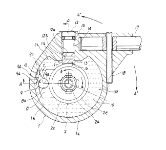
Referring to Figs. 1 through 3, 1 denotes a cylinder, 2 a movable
shaft, 3 a bearing, 4 a setscrew, 5 a bearing, 6 and ? 0-rings, 8 a valve
holder, 9 a movable valve, 10 a functional oil, 11 a partitioning member, 12
an adjust screw, 13 a guide groove, 14 a tapped hole, 15 an 0-ring, 16 an oil
passage, 17 an arm, 18 an angle adjust screw, 19 a metal holdfast, 31 and 32
variable volume chambers.
8
~0~~7~~
The cylinder 1 comprises a tapped section lb disposed near an end
of the inner peripheral surface and a tubular section Ia disposed close to
the other end and provided with a closure ld at the end and is combined with
a circular lid lc having a threaded outer peripheral surface which is held in
engagement with the tapped section lb,
The closure ld of the tubular section la is provided with a shaft
bearing hole le, a circular groove lg and a seal seat Ii while the lid lc is
also provided with a shaft bearing hole lf, a circular groove lh and a seal
seat l,j.
The tubular section la also has a guide groove 13 running on the
inner peripheral surface lk of its thick side wall and a tapped through bore
14 that can bring the guide groove 13 into communication with the outer
peripheral surface of the cylinder 1.
The movable shaft 2 comprises an inner shaft member 2a provided
with a splined section 2b near an end thereof and a serrated section 2f near
'the other end and an outer shaft member 2c engaged with the splined section
2b on the outer peripheral surface o.f the inner shaft member 2a.
'the cap-shaped bearing 3 fitted onto the outer peripheral surface
of the inner shaft near the upper end thereof is held in engagement with the
splined section 2b and rigidly secured to the upper end of the inner shaft 2a
by means of the stepscrew 4.
The cylindrical outer shaft 2c is provided on its outer peripheral
surface 2e with the valve holder 8 having an arcuately recessed holding
section 8a.
The movable valve 9 has a flaplike shape and provided with a
9
cylindrical shaft section 9a projecting downward from the bottom.
The shaft section 9a of 'the movable valve 9 is squeezed into the
holding section 8a of the valve holder 8 and pivotally held there.
The partitioning member 11 has a blocklike shape as illustrated in
Fig. 3.
The partitioning member II .is provided on the inside with a
relatively wide engaging groove Ilb running from an end of the member
substantially to the middle and on the outside with a relatively narrow
engaging groove lla which communicates with the relatively Large engaging
groove Ilb.
The adjust screw I2 which is driven into the partitioning member 11
comprises a neck section 12a disposed near an end thereof and received in the
ongaging groove lIa and a head section 12b disposed at an end of the neck
section 12a and received in the engaging groove 12b.
The above described components will be assembled to a damper
mechanism typically in a manner as described below.
In the first step of assembling operation, 'the lower end of the
inner shaft member 2a is introduced into the shaft bearing hole Ie of the
tubular section la with the interposition of the bearing 5 and the lower end
of the outer shaft member 2c is received in the groove Ig o.f the seal seat li
of the ttabular section la with the interposition of the 0-ring 6.
Now, the movable shaft 2 is set in position in the cylinder 1.
Thereafter, the shaft section of the movable valve 9 is squeezed
into the holding section 8a of the valve holder 8.
The movable valve 9 pivotally fitted onto the outer peripheral
1 0
~~8~'~:~~
surface of the movable shaft 2 is now slidingly movable on the inner
peripheral surface of (the tubular section Ia of) the cylinder 1 to produce a
nonreturn valve 9d between the inner peripheral surface of the cylinder and
the outer peripheral surface of the movable shaft.
Referring particularly to Fig. i, when the movable shaft 2 is
rotated counterclockwise (in the direction as indicated by arrow c), -the
nonreturn valve 9d is released to open itself, whereas it is closed when the
movable shaft 2 is rotated clockwise (in the direction as indicated by arrow
d) .
In the second step, the adjust screw 12 which is holding the 0-ring
15 is driven into the tapped through bore 14 of the tubular section la.
Now, the neck section 12a and the head section I2b of the adjust
screw 12 which is held to the tubular section la project into the guide
groove 13.
Thereafter, when the part itioning member il is squeezed into the
guide groove 13 of the tubular section la, the engaging grooves Ila, llb of
the partitioning member I1 respectively come to be engaged with the neck
section 12a and the head section 12b.
Thus, a partitioning section 11c is formed within the cylinder 1 by
the partitioning member 11.
The narrow oil passage 1& is now produced between the inner front
end of the partitioning member 11 and the outer peripheral surface of the
outer shaft member 2c of the movable shaft 2 as the inner end of the
partitioning member il is brought close to the outer peripheral surface of
the movable shaft 2.
1 1
2~~~'~~a
The position of the partitioning member 11 can be adjusted to
enlarge or narrow the oil passage 16 by moving the member 11 in either
direction of the arrow in Fig. 2 by means of the adjust screw 12.
Thus, the inner space of the cylinder 11 is divided into two
variable volume chambers 31, 32 by the nonreturn valve 9d and the
partitioning section llc and the two variable volume chambers 31, 32 are held
in communication with each other by way of the oil passage 16.
The variable volume chambers 31, 32 are filled with functional oil
in this stage of assembling operation.
In the final stage of assembling operation, the lid Ic carrying the
0-ring 7 on its seal seat lj is fitted to the opening of the tubular section
la to airtightly seal the inner space of the cylinder 11 by way of the mutual
engagement of the tapped section lb and the corresponding threaded section
(not designated by a reference symbol).
Under this condition, a top portion of the inner shaft member 2a
that carries the bearing 3 is squeezed into the shaft bearing hole if while a
top portion of the outer shaft member 2c is squeezed into the groove lh of
the lid lc.
The arm 19 is fitted to the outer periphery of (the tubular section
la of) the cylinder 1 by means of the angle adjust screw 18 and the metal
holdfast 19 is fitted to the serrated shaft section 2f of (the inner shaft
member 2a of) the movable shaft 2 projecting out of the (tubular section la
of) the cylinder 1.
All the components and members of a damper mechanism according to
the invention are made of metal and/or hard synthetic resin except the
1 2
2~~~~~~
sealing members which are made of rubber or synthetic resin of a known type.
The functional oiI 10 may be any viscaus fluid (oil) or oily
viscous and elastic fluid selected from silicon oil, grease and high
molecular substances.
The above described embodiment o.f damper mechanism of the present
invention may be modified in various ways.
A possible modification is that the partitioning member 11 is
rigidly secured to the inner peripheral surface lk of the cylinder 1.
With such an arrangement, a through bore is bored through either
the movable valve 9 or the partitioning member 11 and serves as an oil
passage 16.
Another modification is that both the movable valve 9 and the
partitioning member 11 are provided with an oil passages 16.
With such an arrangement, the oil.passage through the movable valve
has a cross section smaller than 'that of the oil passage through the
partitioning member 11.
Still another possible modification is that a plurality of
combinations of a nonreturn valve 9d and a partitioning section llc are
arranged in a manner same as or similar to that of arrangement of the above
described embodiment.
With such an arrangement, the inner space of the cylinder 1 is
divided into four or more than four variable a chambers.
Fig. 4 illustrates a swing Iid (door) to which the embodiment of
damper mechanism of the invention is applied.
In Fig. 4, an arm 22 is articulated at an end to a corresponding
1 3
2~~~'~~~
end of another arm 17 whose other end is rigidly secured to the cylinder of
the damper mechanism while the other end of the arm 22 is pivotally connected
to a metal holdfast 23.
A cabinet 20 as illustrated in Fig. 4 is provided at an edge of its
opening 21 with a swing lid 25 which is anchored to the cabinet 20 by means
of a hinge 24.
Another metal holdfast 19 is rigidly secured to the inner surface
of a lateral wall of the cabinet 20 near the opening 21 by means of screws.
The metal holdfast 23 is, on the other hand, rigidly secured to the lower
surface of the swing lid 25 by means of screws.
Thus, the damper mechanism comprising the arms 17, 22 and other
components operates like an elbow disposed between a portion of a lateral
wall of the cabinet 20 near the opening of the cabinet 20 and the swing lid
25.
If the swing lid 25 is turned from its closed position as indicated
by solid lines in Fig. 4 t o an open position as indicated by phantom lines
in Fig. 4, the cylinder 1 is rotated by means of the arms 17, 22 in a
direction as shown by arrow b' relative to -the movable shaft 2 which is
rigidly secured to a lateral wall of the cabinet 20 near the opening 21 by
means of the metal holdfast 19.
As the cylinder 1 is rotated, the nonreturn valve 9d is opened to
allow the functional oil 10 contained in the variable volume chamber 32 to
smoothly flow into the other variable volume chamber 31 so that the lid 25 is
turned open without any substantial resistance.
If, then, the swing lid 25 of 'the cabinet 20 is turned back from
1 4
2~~~'~~~
the open position as indicated by phantom lines to the closed position as
indicated by solid lines in Fig. 4, the cylinder 1 is rotated in a direction
as shown by arrow a' which is opposite to the direction shown by arrow b'.
As the cylinder 1 is rotated, the nonreturn valve 9d is closed and
the variable volume chamber 31. is compressed by the movable valve 9 whereas
the other variable volume chamber 32 is expanded to an equal extent.
Under this condition, since the functional oil 10 contained in the
compressed variable volume chamber 31 is partly fed to the expanded variable
volume chamber 32 by way of the oil passage 16 so that the movable shaft 2
is slowly rotated to softly close the .lid 25.
The angular speed of the movable shaft 2 and that of the lid 25 are
determined by the flow rate of functional oil running through the oil passage
16.
Thus, the angular speed of the closing li.d 25 can be appropriately
selected by moving the inner front end of the partitioning member 11 closer
to or away from the outer peripheral surface of the movable shaft 2 and
therefore by adjusting the cross section of the oil passage 16.
A damper mechanism according to the invention and capable of
exerting an above described damping effect can advantageously find various
applications where a component of a structure is rotated in two opposite
directions and the rotation of the component is natural in a given direction
whereas the rotation in the other direction need to be controlled.
(Industrial Applicability]
As described above, a damper mechanism according to the invention
has a simple configuration of comprising a mova'ale shaft housed in a cylinder
1 5
along with a nonreturn valve, a partitioning member and an oil passage and
the variable volume chambers formed within the cylinder and separated by the
nonreturn valve and the partitioning member are filled with functional oil.
A damper mechanism according to the invention produces an effect of
damping any rotary movement of the movable shaft when the movable shaft is
rotated in a given direction.
Thus, it is only a movable valve which is a principal component of
the nonreturn that is subjected to contact and .friction with the inner
peripheral surface of the cylinder while the damper mechanism is operated,
whereas any other components thereof are practically not subjected to
friction.
Moreover, the movable valve is subjected to contact with the inner
peripheral surface of 'the cylinder only when the damper mechanism produces a
damping effect and, because the contact between the movable valve and the
cylinder is very soft and mild, either of them will not be abraded.
Additionally, since 'the movable valve operates as a blade for
driving functional oil to flow and as a nonreturn valve for blocking the flow
of functional oil, the overall number of components of such a damper
mechanism is advantageously reduced.
Thus, a damper mechanism according to the invention can be
economically manufactured, stably operates for a prolonged period of time and
has an excellent durability. Such a damper mechanism can advantageously find
various applications where a damping effect is required.
1 6