Note: Descriptions are shown in the official language in which they were submitted.
8~2~
MODULAR SHAPING AND ~RIAL REDUCTION GUIDE FOR IMPLANTATION
OF POSTERIOR-STABILIZED FEMORAL PROSTHESIS AND METHOD OF
USING SAME
S Thiæ invention generally concerns orthopedic
surgical devices, particularly instrumentation used in
preparing a distal femoral bone surface to receive a
posterior-stabilized condylar prosthesis~ as well as a
method of using such instrumentation.
During surgical implantation of femoral condylar
prostheses, it is typically necessary to utilize some type
of tool to gauge whether or not the distal aspect of the
femur has been properly sized to receive the condylar
implant. This gauge typically resembles the actual
prosthesis which will be implanted. The surgeon first
~resects" the surface of the bone to match the geometry of
the implant by making several cuts as shown, for example,
in U.S. Patent No. 4,474,177 to Whiteside.
Once the distal aspect of the femur has been
resected, a convex patellar groove is formed in the
anterior surface of the resected bone, in order to
accommodate the mating concave patellar track of the
condylar implant. In a total knee replacement, the
external distal surface of the condylar implant, including
that of the patellar track, articulates with the proximal
aspect of an implanted tibial component. A previously
devised cutting guide for shaping the patellar groove i8
the subject of U.S. Patent No. 5,035,699 and assigned to
the instant assignee. Depending upon the degree of knee
reconstruction indicated, a patellar prosthesis may also be
implanted as shown, for example, in U.S. Patent No.
5,019,104 and also assigned to the present ascignee.
A challenge confronted by condylar implant
systems is the need to both accurately form a patellar
groove in the resected surface of the distal femur and
perform a trial reduction of the knee joint to ascertain
. -- 1
~982~
proper sizing of the condylar implant. This i8
conventionally a sequential procedure ~mploying first a
guide seated on the resected bone for engaging a shaping
tool which forms the patellar groove in the bone.
Secondly, a trial condylar implant is seated on the
resected surface of the distal femur, having a size and
- shape resembling that of the permanent condylar prosthesisactually being implanted, after which the trial reduction
of the knee is performed by articulating the femur and
tibia. Following satisfactory trial reduction, the trial
implant is removed and replaced by the permanent condylar
implant. A disadvantage of the procedure set forth above
is degradation of the bone caused by alternate insertion
and removal of separate track cutting and trial implant
guides respectively. Moreover, use of separate track
cutting and trial implant guides is relatively inefficient
and time consuming, further complicating the urgical
procedure for reconstructing the knee joint.
U.S. Patent No. 4,721,104 to Xaufman and
Whiteside, describes a femoral shaping apparatus employing
a template having a straight slot therein for cutting a
relatively deep recess for an intercondylar stab~lizing
housing of a knee implant. The patented system also
describes a trial implant module, however, it does not
disclose a cutting guide having a curved track ufieful for
forming a groove to accommodate a patellar track on such a
prosthesis.
U.S. Patent No. 5,098,436, assigned to the
instant assignee, shows using common surgical
instrumentation to form both a groove and deep recess in
the resected distal femur, respectively accommodating a
patellar track and intercondylar stabilizing housing of the
implant, but does not disclose a modular system also
capable of performing a trial ~oint reduction. U.S. Patent
No. 5,100,409, also assigned to the instant Assignee, shows
a device and method which combine the features of a femoral
~ U b ~
trial implant ~nd patellar track cutting guide, 80 that the
patellar groove may be 6haped and a ~urgical trial
reduction of the total knee joint accurately performed
using common instrumentation. However, thLs patent doe6
not show how such modular instruments could be modified to
also form a deep recess in the distal femur to accommodate
the intercondylar housing of a posterior-stabilized femoral
component.
Accordingly, there remains a need for modular
instrumentation which can be employed to form both a
patellar groove and deep recess in the resected surface of
a distal femur using a common guide which also functions to
perform a trial reduction of the total knee joint.
According to the invention, there is provided a
trial implant comprising a modular bracket defining a
structure having an internal surface adapted to be seated
on the distal aspect of a resected femur and an external
surface with a shape resembling the normal distal condyle
of the femur. The bracket hag an elongated central openinq
appointed to expose the resected surface of the femur,
including means for guiding a first shaping tool alonq a
predetermined path for controlled shapinq of a patellar
groove in the surface exposed throuqh the openinq. Means
are provided for guiding a 6econd 6haping tool for forminq
a deep recess in the distal femur to accommodate an
intercondylar hou6inq of a posterior-stabilized femoral
component and i8 replaced with an insert covering the
opening and provided with a posterior-stabilizing housing
which articulates with a proximal aspect of the tibia for
interoperative trial reduction of the knee joint without
removal of the bracket from the resected distal surface.
According to the invention, a method of
implanting a posterior-stabilized femoral prosthesis
comprises the steps of resecting the distal aspect of the
bone to receive a trial implant thereon. The trial implant
provided comprises a bracket defining a modular structure
- 3 -
g 2 ~
having an internal surface adapted to be seated on the
distal aspect of the femur and an external surface formed
with a shape resembling the normal distal condyle,
including an elongated central opening appointed to expose
an anterior distal resected surface of the femur to a first
shaping tool. The method further comprises the step of
providing means for guiding the first shaping tool along a
predetermined path for controlled shaping of the anterior
distal surface exposed through the opening. The first
shaping tool is moved along the path, cutting or abrading
a patellar groove in the distal surface. Means are
provided for guiding a second shaping tool during a step
which forms a deep rece s in the distal 6urface to
accommodate an intercondylar housing of the posterior-
stabilized femoral componQnt. A trial insert having a
posterior-stabilizing housing and cooperable with the guide
means is brought into secure engagement with the opening,
covering the area of the patellar groove. The in~ert and
bracket function as a trial implant a6 the femoral and
tibial component are articulated during a stQp which
includes the trial reduction of the total knee ~oint.
An advantage of this invention i8 a device and
method of using the device by which a patellar groove and
deep recess of a posterior-stabilized femoral component may
be shaped in a resected femur using common instrumentation
which also functions as a trial implant during trial
reduction of the total knee joint.
Another advantage of this invention is a method
and a device by which excessive wear on the distal aspect
of the femur i8 avoided by replacing the use of multiple
instruments with a single modular device.
The above and other objects and advantages of the
present invention will become apparent to those skilled in
the art upon an examination of the following detailed
description and drawings which are illustrative of the
present invention wherein:
- 4 -
~,J ~
FIG. 1 is a internal perspectivQ view of an
existing trial, ~hown with the first insert in place for a
regular condylar implant;
FIG. 2 i8 a side elevation view of the trial
implant of FIG. l;
FIG. 3 is an exploded perspective view of the
trial implant of FIG. 1, showing the modular bracket being
~eated on the resected distal femur with the first insert
removed:
FIG. 4 is a frontal view of the modular bracket
of the invention seated on the resected distal femur, ~hown
being used in combination with the first shaping tool for
shaping the patellar groove in the bone;
FIG. 5 is a frontal external view of the bracket
alone, illustrating cooperation of the guide means for the
first shaping tool along with that tool;
FIG~ ~ i8 an external frontal view of the trial
implant of FIG. 1, 6howing the first insert securely
positioned within the opening of the bracket and
articulating with a tibial prostheQis during the trial
reduction of a non posterior-stabilized knee ~oint;
FIG~ 7 is an exploded frontal view of the
assembly for forming a deep recess in the distal femur to
accommodate an intercondylar hou~ing for a posterior-
stabilized femoral component;
FIG. 8 is a side elevational view of the means
for guiding the second shaping tool of the lnvention for
forming a deep recess in the distal femur, shown resting on
the bracket which is indicated ln phantom;
FIG. 9 shows the guide means of FIG. 8 alone
apart from the bracket;
FIG. 10 is an exploded side elevational view of
the bracket of FIG. 8, in combination with a trial insert
adapted for reduction in a posterior stabilized total knee
joint;
2 ~
FIG~ 11 is an exploded frontal view of the
combination of FIG. 10; and
FIG. 12 i8 an external perspective ViQW of a
femoral trial component having a posterior-ctabilizing
housing with modular revision stem.
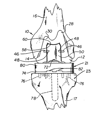
Referring to FIG. 1, a trial implant i8 generally
shown at 10 comprising a modular bracket, generally
indicated at 12, defining a structure having an internal
surface (facing the viewer) adapted to be seated on a
resected distal aspect, generally indicated at 14, of a
resected femur bone, shown at 16 in FIGS. 3, 4 and 6. With
particular reference to FIGS. 3, 5 and 4, the bracket has
an external surface (facing the viewer) resembling the
normal distal condyle of the femur and an elongated central
opening, generally indicated at 18 which is appointed to
expose the resected distal aspect 14 of the femur 16.
Means are provided in the form of parallel tracks or rails
20 for guiding a first shaping tool, generally indicated at
22 along a predetermined path in the direction of arrow 24
for controlled shaping of a patellar groove 26 (FIG. 4) in
the bone exposed through the opening 18. A replaceable
insert, generally indicated at 19 (FIGS. 1 and 3), covers
the opening 18 and articulates with either the normal
surface or a prosthesis 21 which is implanted on the
resected surface of the proximal aspect 23 of the tibia
bone during interoperative trial reduction of the knee
~oint as shown in FIG. 6.
Referring to the FIG. 1, the internal surface of
the trial implant 10 is shown comprising a medial 28 and
3Q lateral 30 portions of an anterior condylar flange, a pair
of posterior condylar flanges 32 which define an
intercondylar notGh 34 and a series of planar areas.
Specifically, the planar areas comprise a smooth metal
finish, since tissue ingrowth into the internal surface of
the trial implant 10 is not necessary and, in fact, a non-
abrasive action is desirable in seating the trial implant
- 6 -
`~a~2~
10 on the resected distal aspect 14 of the femur 16. With
additional reference to FIG. 2, the planar surfaces which
compri~e the internal surface of the trial implant, as
shown with the insert 19 positioned in the opening 18
(FIGS. 1-2) include a posterior 36, distal 38 and anterior
40 surface. A humped distal internal contact surface 42 of
- the trial implant 10, constitutes the internal surface of
the insert 19. Likewise, the internal 6urfaces of the
posterior condylar flanges 32 and the medial 28 and lateral
30 portions of the anterior condylar flange, respectively,
also have a smooth metal finish to facilitate placement
onto and off from the resected bone. The cleaner sur*ace6
correspond to the resection cuts made in the distal aspect
14 of the femur 16. A pair of pegs 44 are formed in the
planar surface 38 and project into corresponding holes 45,
shown in phantom in FIGS. 3 through 4, bored in the distal
aspect 14 of the femur 16.
Referring to FIG. 3, the bracket 12 has a pair of
alignment notches 46 on opposed sides of opening 18, which
nlign with a pair of corresponding notches 48 formed on
opposed sides of the insert 19. The insert 19 further
comprises a central concave patellar track 50 and a pair of
opposed lateral flanges 52 on either side of the patellar
track 50. The lateral flanges 52 engage the rails 20 of
the bracket 12. The insert is securely positioned in place
on the bracket by a pair of opposed studs 54 which meet
with a corresponding pair of apertures 56 formed in the
external distal surface of the bracket 12. The insert 19
has an interior shoulder 58 which engages in abutment ledge
60 formed in the interior of the bracket 12. The insert 19
may be readily positioned within the opening 18 of the
bracket 12 by means of a gripping aperture 62 formed in the
patellar track 50 of the insert 1g; likewise, the alignment
notches 48 may also facilitate interoperative removal and
replacement of the insert within the opening 18 as needed.
i v ~ ~ ~2 il
Referring to FIG. 4, the first shaping tool 22
further comprises a drive shaft 64 rotatably mounted by
means of a bearing sleeve 66 to a cutting element,
generally indicated at 68, having a plurality of convex-
shaped ribs which cut and/or ~brade the resected surface of
the distal femur to form the patellar groove 26.
Referring to FIG. 5, the bearing sleeve 66
extends outwardly from either side of the cutting element
68 and does not rotate with the cutting element 68.
Rather, the bearing sleeve 66 rotates independently of the
cutting element 68, engaging and travelling along the rails
20 which establishes the predetermined path indicated by
the arrow 24 to shape the patellar groove.
once the patellar groove 26 has been formed in
the manner described above, the insert is replaced into the
opening 18 and the knee joint is relocated, as shown in
FIG. 6 where the proximal aspect 23 of the tibia 17 has
also been resected and a tibial prosthesis 21 implanted, so
that the articulating process of the tibial implant engages
the patellar track 50 of the condylar prosthe~is. The
tibial prosthesis 21 may be selected from any of a variety
of conventional types available to those skilled in the
art. The tibial prosthesis 21 preferably comprises a metal
base plate 74 which is implanted into the resected proximal
aspect 23 of the tibia 17 by means of pairs of lateral
pegs, shown in phantom at 76 and a central long stem 78
which is fit into the intermedullary canal of the t~bia 17.
The tibial implant 21 ifi of modular construction, further
comprising an upper articulating portion 80, preferably
formed of a hard pla~tic material, for example, high
molecular weight polyethylene, to provide a non-degrading
articulating surface. The upper portion 80 locks into
place within the metal base 74 by means of an arrangement
of notches 82 and the upper portion may be replaced when
worn without removing the metal base 74 implanted into the
bone.
-- 8 --
2 4
Modular surgical instrumentation ~nd a method of
using same a8 described in conjunction with FIGS. 1-6 ~bove
is adapted to form a deep recess in the distal femur to
accommodate an intercondylar housing of a posterior-
~tabilized femoral component, according to the invention,
as further shown in FIGS. 7-12. This instrumentation
(bracketed in FIG. 7) comprises a bracket 312, which has
essentially the ~ame construction as the bracket 12
illustrated in FIG. 1 and 3-4 and need not be further
described in detail here. The bracket 312 defines a
generally U-shaped structure which i6 seated on the distal
aspect of the resected femur 313 and has the elongated
central opening 323 appointed to expose a selected area of
the femur, including ledges 340, 342 for guiding the first
shaping tool, along a predetermined path for controlled
shaping of a curved patellar groove in a portion of the
selected area exposed through the opening, substantially as
described above with reference to FIG 3. MeanR generally
shown at 300 for guiding a second shaping tool defines a
linear bore 302 (shown in phantom~ receiving a second
shaping tool in the preferred form of an end mill.
Generally indicated at 304 rotating in the direction of
arrow 306 and movable axially in the direction shown by
arrow 308, i.e., downwardly toward the resected femur 313
essentially parallel to the long axi~ of the femoral
medullary canal 311 (shown in phantom). Bore 302 may have
a pair of slots (not shown) which extend tangentially from
the bore for receiving a U-shaped punch of the type shown
in aforementioned U.S. Patent No. 5,098,436 or an osteotome
(not shown), downwardly in the direction of arrow 308
through the bore 302 to form, together with the end mill
304, a relatively deep elongated reces~ in the femur, as
will be described in conjunction with FIG. 11. The guide
means 300 further comprises a top 314 which is essentially
perpendicular to the long axis of the femur and through
which bore 302 is formed.
_ g _
~ J ~2 ~
Referring to FIGS. 7-9 and 10-12, extending
perpendicularly from the top 314 are a pair of lQgs 316
each having seats 318 which extend in an anterior-posterior
direction and have a curved shape to engage the ledges 340,
342 of bracket 312. Guide means 300 i~ aligned with
respect to bracket 312 by a pair of positioning holes 320,
322 which respectively engage a pair of pegs 324 projecting
distally from the bracket 312, to securely lock the guide
means 300 into proper position with respect to bracket 312.
The bracket 312 can be further secured either to the bone,
guide means or both by any suitable arrangement of clips,
clamps or the like as will be readily appreciated by those
skilled.
End mill 304, shown in FIGS. 7-9, has a shoulder
328 which bottoms-out in the stop 330 formed at the distal
end of bore 302. After end mill 304 is thus brought down
into the surface of the resected femur 313 and then
withdrawn, the punch or osteotome alluded to above is
impacted with a mallet or the like to finish forming an
elongated deep recess for the intercondylar stabilizing
housing, until the tip of such punch or osteotome reaches
the bottom of the hole formed by end mill 304.
Referring to FIGS. 10-11, following formation of
the deep recess, the surgeon replaces the guide means 300
with a different insert, generally shown at 332 which has
been modified with a posterior-stabilizing housing, the
combination of insert and bracket being collectively
denoted by reference numeral 310. The insert 332 is
positioned on the bracket 31~ by locator fingers 334
engaging slots 335, the bracket being, in turn, located on
the bone using pegs 336 (FIG. 10). The modified insert 332
further comprises an internal wall, indicated in phantom at
338, defining the housing 340, also shown in phantom in
FIGS. 10-11. A tapered female morse-type connector 342 is
provided adjacent the housing 340, receiving a tapered male
morse-type connector 344 from a trial stem 346 via keyway
-- 10 --
;~;b~g2~
348 which receives key 350, as ~hown by FIG. 12. Except
for the housing 340 and tapered connectors 342, 344, the
~tructure and function of the modular trial component of
FIGS. 10-12 is used in performing trial reduction of the
kneQ joint ~imilarly to the femoral trial component
discussed relative to FIGS. 1-6 above.
- The method of the invention comprises the ~teps
of seating the bracket described above on the distal aspect
of the resected femur and moving the first shaping tool
along the curved track to form a patellar groove in a
selected area thereof. The first shaping tool i~ then
withdrawn and, leaving the bracket in place, while the end
mill guide means discussed above relative to FIGS. 7-9 is
seated on the curved track so that the slotted bore of the
guide is accurately aligned with the opening of the
bracket, after which the end mill is introduced through the
bore to form a deep recess accommodating the intercondylar-
stabilizing housing of the trial implant and the trial
reduction of the posterior-stabilized knee joint i6
performed.
These and other variations of the present
invention may be made which fall within the scope of the
appended claims even though such variations were not
specifically discussed above.