Note: Descriptions are shown in the official language in which they were submitted.
2/U41)~X l'~_ l / U~ 5~4
T~TLE - 1 - 2089887
CONTACT LENS PURIFICA TION SYSTEM
BA CKGROUND
One of the biggest problems for wearers of
contact lenses is the cleaning and disinfecting that these
require. If dirt and microorganisms are not to enter the
eye with the lenses, these must be cleaned, soaked, and
disinfected using specified steps, materials, and treat-
ment schedules for each type of contact lens. In spite of
all the recommendations, lens wearers do suffer eye
problems from poor lens hygiene, and it is well known that
many lens wearers do not follow the suggested procedures
faithfully enough to avoid eye problems from contact
lenses introducing dirt and microorganisms into the eyes.
To help with the problem of contact lens
hygiene, my invention applies ozone purification to the
disinfecting of contact lenses. In doing so, I have
focused on simple and effective systems that are
inexpensive to manufacture and easy and convenient for a
user to operate. My systems for purifying contact lenses
facilitate the wearer's desire for simple and reliable
lens disinfection, require minimum involvement by the
wearer, and minimize chances of a failure. Achieving
these goals with a small and inexpensive lens purifier is
an intricate problem solved with varying degrees of
sophistication by the several embodiments disclosed in
this application. These embodiments use ozone for
purifying the lenses, and they generate the ozone and
apply it to the lenses in systems that represent
approximately a 1000:1 reduction in scale from the present
art of oz~ ~ purification.
SUMMARY OF THE INVENTION
My contact lens purification system brings a
lens to be disinfected into contact with ozone, either
2089887
dissolved in liquid or in a gaseous state, or both. The
lens is held in a treatment chamber where the ozone
contact occurs, while the lens is either submerged in or
sprayed with a purifying liquid. A generator produces the
ozone, and a pumping system that can include a gas pump, a
liquid pump, or both, mixes the generated ozone with a
purifying liquid and brings one or both into contact with
the lens. My system also involves a compact device that
can hold lenses in a convenient position for purification
and can automatically operate the ozone generator and the
pumping system for disinfecting the lenses. Appropriate
purification can be timed and sensed, and any escape of
ozone from the device can be made negligible.
DRA WINGS
All of the drawings are partially schematic
diagrams of different preferred embodiments of my contact
lens purification system. Each embodiment includes an
ozone generator, a lens chamber where contact lenses can
be purified, a pumping system for bringing ozone and a
purifying liquid into contact, a reducer for diminishing
the concentration of any escaping ozone, and a controller
to ensure that lens purification occurs. The various
embodiments of the drawings differ from each other in that:
Figure 1 shows a gas pump arranged for flowing an
ozone containing gas through the ozone generator and for
pumping purifying liquid in a circulation loop that
includes a bubble line and a gas/liquid separator.
Figure 2 shows a pump arranged for pumping both
purifying liquid and an ozone containing gas through a
circulation loop.
Figure 3 shows a liquid pump arranged for forcing
liquid through a venturi where it is combined with an
ozone containing gas in a circulation loop that includes a
gas/liquid separator.
~7'
.
~ / uL{u~
3 2089887
Figure 4 shows a gas pump arranged for forcing an
ozone containing gas through an ozone generator and
directly into a lens chamber where lenses are contacted by
both gaseous and dissolved ozone.
Figure 5 shows a gas pump arranged for forcing an
ozone containing gas through an ozone generator and
through a venturi spray nozzle that combines ozone with a
purifying liquid sprayed onto contact lenses.
Figure 6 shows a liquid pump arranged for forcing a
mixture of a purifying liquid and an ozone containing gas
entrained with the liquid through a nozzle directing a
spray onto contact lenses.
DETAILED DESCRIP7'ION
The preferred embodiments of the drawings have
comparative advantages in features such as convenience,
reliability, safety, cost, and compactness. Different
embodiments, using different combinations of such
features, may be preferred for different types of lenses
or for users with different desires. The embodiments will
be explained in the order presented in the drawings, but
this does not imply any similar order of importance.
Also, some of the different features that are illustrated
in the drawings can be interchanged among the various
embodiments, and the drawings are arranged to illustrate
the different features that can be combined, and not to
delimit one combination of features from another.
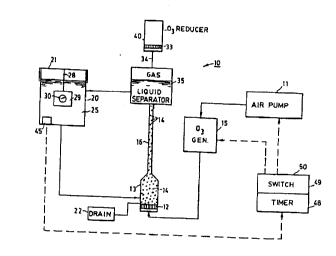
System 10 of FIG. 1 uses an air pump 11 as a
prime mover, to cause the necessary gas and liquid flows
o make the system work. Air pump 11 is preferably
arranged upstream of ozone generator 13 so that it can
force air through generator 15, which outputs a mixture of
air and ozone. Pump 11 could be arranged downstream of
ozone generator 15, except that an ozone environment is
too corrosive and problematic for most pumps to handle.
_ 4 _ 2089887
The air and ozone mixture output from generator
15 is delivered to a diffuser 12 arranged at the entry to
a chamber 13 that also receives purifying liquid 25 from
lens chamber 20. Diffuser 12 is porous and allows gas to
flow through, preferably in a way that divides the gas
flow into a multitude of bubbles 14. Although air stones
and other materials are available for diffuser 12, I
prefer a porous, hydrophobic resin material that allows
the air and ozone mixture to flow through, but resists any
flow of liquid 25 in the opposite direction. Diffuser 12
can then serve as a liquid barrier ensuring that no
purifying liquid 25 travels back to generator 15. This is
important because the preferred form of generator 15 is a
corona discharge device that would be damaged if liquid
were to enter it.
Another way to ensure that liquid does not
enter generator 15 is by directing the output from
generator 15 to a level higher than the purifying liquid
level within the system so that gravity prevents liquid
from flowing through the elevated passageway to generator
15. This would require that the system not be turned over
while it contains liquid 25 or that the elevated
passageway includes a trap large enough to hold all the
system liquid, if the system is turned over. A check
valve can also be arranged in the output line from
generator lS; and a check valve, like the porous
hydrophobic resin material preferred for diffuser 12, can
protect generator 15 from liquid 25, even if the system is
overturned.
Purifying liquid 25 can be water or saline
solution and can possibly contain other materials
beneficial to the cleaning and disinfecting of lenses 30.
These are arranged in a holder or container 29 that
permits liquid 25 to contact lenses 30. Container 29 is
mounted within lens chamber 20, preferably by an element
28 that suspends container 29 from cover 21. In the
~ L/ I~- U~ r~ 1 / u~ I ~ v~o~-~
- 5 ~ 2089 887
embodiment of FIG. 1, container 29 and lenses 30 are
submerged under purifying liquid 25 in which ozone is
dissolved so that flow of liquid 25 through chamber 20
contacts lenses 30 and purifies them by killing micro-
organisms and attacking other contaminants, as is
generally known in the ozone purification art.
Although ambient air is a simple and preferred
input for generator 15, it is also possible to use dried
air that has passed through a dryer, to help keep moisture
out of generator 15. Another possibility is supplying
oxygen from a small container serving as the input to
generator 15, which can produce more ozone from an oxygen
supply than from an air supply.
A drain 22 is a convenient feature for system
10, so that purifying liquid 25 can be drained out
whenever desired. This is especially important if system
10 is designed so that it should not be tilted for pouring
liquid out of chamber 20. Also, it may be desirable in
using purified liquid 25 for filling a lens storage case
or for rinsing and cleaning out a lens holding case. For
any of these purposes, drain 22 is preferably at the
lowest liquid level within system 10, which in the
illustration of FIG. 1 puts drain 22 at the bottom of
chamber 13.
The amount of liquid 25 in system 10 is
preferably predetermined, by the user pouring in the
proper amount, for example. If saline solution is desired
for liquid 25, this can be made within system 10 by adding
a proper sized salt tablet to distilled water. Operation
of system 10 purifies liquid 25, w le purifying lenses
30, so that any contamination enterlng system 10 with a
charge of liquid 25 can be purified by the ozone that
circulates within system 10.
2089887
-- 6
From chamber 13, where the air and ozone
mixture from generator 15 is combined and contacted with
purifying liquid 25 from chamber 20, a bubble line 16
extends to gas and liquid separator 35. Bubbles 14,
rising in bubble line 16, make purifying liquid 25 flow
with them from chamber 13 to separator 35. Bubble line 16
thus serves as a circulation pump for purifying liquid 25,
under the motive power of air pump 11. Bubble line 16
then draws liquid 25 from chamber 20 into chamber 13, and
on to separator 35 from which liquid flows back into
chamber 20. In passing through chamber 13, bubble line
16, and separator 35, liquid 25 dissolves some ozone that
enters chamber 20, to contact and purify lenses 30.
Air and any ozone that does not dissolve in
liquid 25 within chamber 13, bubble line 16, and separator
35 are directed through vent 34 to an ozone reducer 40
that greatly reduces the concentration of ozone in gas
escaping from separator 35. Reducer 40 contains at least
one of several materials that are available for reducing
ozone to oxygen so that raw ozone does not escape into the
atmosphere. Even if raw ozone were to escape through vent
34, however, it should not present any health hazard in
the small quantities used for operating system 10.
When reducer 40 is used and is filled with a
catalytic or other material that reduces ozone to oxygen,
it is important that purifying liquid 25 not reach the
material within reducer 40, because liquid would impair
its action. Working against this is the fact that bubbles
14 are entering separator 35 and bursting at the liquid
surface there, creating spray droplets that can enter vent
34. Baffles are one possibility for keeping these spray
droplets out of reducer 40, but baffles would not block
liquid flow if the system were overturned. What I prefer,
therefore, is a porous hydrophobic resin element 33 that
allows gas, but not liquid, to entér reducer 40.
.,~,.
2089887
-- 7
The system of FIG. 1 is preferably operated by
a controller 50 that includes a switch 49 and a timer 48.
The user preferably initiates a purifying cycle by
operating switch 49, and the duration of the purifying
process is controlled by timer 48. Starting up system 10
involves actuating air pump 11 and generator 15, and these
should run for a long enough interval to purify lenses
30. It is desirable that system 10 run no longer than
necessary for adequately purifying lenses 30, and the
duration of operation can be controlled in several ways.
A simple and preferred way is to set timer 48 for a
predetermined interval so that once switch 49 is actuated,
pump 11 and generator 15 operate for the timed interval
before shutting off. This interval should be established
to assure that liquid 25 is purified and lenses 30 are
adequately contacted with ozone to ensure their
purification. Depending on the ozone output rate of
generator 15, two to ten minutes should suffice.
Sensor 45 can be arranged in lens chamber 25,
or elsewhere in contact with liquid 25 containing
dissolved ozone; and sensor 45 is placed in communication
with control unit 50. Sensor 45 can detect a
concentration of ozone in purifying liquid 25, and
controller 50 can be made to act responsively to the ozone
concentration information from sensor 45. Ozone
purification involves both concentration of ozone and time
of contact of lenses 30 with the ozone concentration. The
more diluted the ozone concentration, the longer the time
required for purification, and vice versa. By adding a
simple microprocessor to controller 50, system 10 can be
operated for a time interval suitable to the concentration
of ozone in liquid 25 in chamber 20, as detected by sensor
45, to ensure that lenses 30 are appropriately disinfected
when a purification cycle ends.
- 8 - 2089887
Sensor 45 can also be used in a more simple
arrangement for merely verifying that ozone generator 15
is operatin~ and delivering ozone to liquid 25 in lens
chamber 20. For this, if sensor 45 does not detect ozone
in liquid 25, a warning or indicator light could be
illuminated to inform the operator that lenses 30 are not
being purified.
System 17 of FIG. 2 differs from system 10
primarily in the ways that venting, pumping, and liquid
and gas flows occur. Venting is through the cover 21 of
lens chamber 20, instead of from a gas and liquid
separator, but otherwise venting preferably includes vent
34, porous hydrophobic element 33, and reducer 40 that
reduces the concentration of any ozone escaping to
atmosphere.
The prime mover for flow in system 17 is pump
23, arranged for pumping both purifying liquid 25 and a
gas mixture that includes ozone, which flows from
generator 15 and combines with liquid 25 at a T 24. Pump
23 is preferably a positive displacement pump, such as a
gear pump, which helps mix and contact together the ozone
mixture and the purifying liquid. The piping of these
materials to pump 23 is sized to proportion the respective
flows for combining ozone with the liquid at a desirable
rate and for providing an adequate circulational flow
through lens chamber 20 to ensure that lenses 30 are
contacted by ozone dissolved in purifying liquid 25. The
circulational flow can also be arranged for directing
liquid flow over the surfaces of lenses 30 at a rate that
is adequate for removing dirt particles from lenses 30,
which can thus be cleaned by the combined effects of ozone
purification and agitational contact with liquid.
.~
W~ /1)4U~X ~ I/U~YI/U:~0~4
- 9 - 2089887
A filter 26 can be arranged in the line between
lens chamber 20 and junction 24, but filter 26 can also be
omitted. Ozone contact may precipitate some materials
from purifying liquid 25, depending on its purity when
introduced into the system; and impurities may be removed
from lenses 30, from the agitation action of the ozone and
the purifying liquid 25 that flows over lenses 30. Either
impurity can be captured by filter 26. Also, a desirable
drain 22 for system 17 can allow liquid 25 to be changed
frequently enough so that filtration may not be necessary.
A check valve 27 is shown in the line between
ozone generator lS and T junction 24, to ensure that
liquid 25 does not enter generator 15. Other
alternatives, as previously explained, can include
elevating the output line from generator 15 to a level
above liquid 25 or using a porous hydrophobic element to
block liquid back flow.
A static mixer 31 is shown downstream of pump
23, to ensure thorough mixing of the liquid and gas before
these reach lens chamber 20. Mixer 31 can be eliminated
whenever pump 23 itself provides adequate mixing. Static
mixer 31 can also be arranged downstream of the gas and
liquid contact region in other embodiments where
additional liquid and gas mixing is desirable.
The control of system 17 can be similar to the
control described for system 10. Also, the separator 35,
with its ozone reducer 40, can be incorporated into system
17, rather than venting gas through chamber cover 21.
System 18 of FIG. 3 is similar to system 10,
except for the pumping and combining of the liquid and
gas. Liquid pump 36 pumps liquid from lens chamber 20
through venturi 37 where an air and ozone mixture from
generator 15 is entrained with the flowing liquid.
Purifying liquid 25 can flow through filter 26 enroute to
2089887
-- 10 --
pump 36, if desired, and a check valve 27 or other
restriction against liquid backflow can be arranged in the
output line from ozone generator 15. Venturi 37 is sized
to entrain the ozone gas mixture at a flow rate that is
appropriate to the liquid output flow from pump 36.
Venturi 37 also contacts the liquid and gas phases
together and helps mix these two to facilitate dissolving
ozone within the liquid. A static mixer 31, such as shown
in system 17 of FIG. 2, can be arranged downstream of
venturi 37, if necessary, to ensure adequate mixing of gas
and liquid.
System 18 can use a similar control 50, gas and
liquid separator 35, ozone reducer 40, lens container 29,
and drain 22 as previously described for systems 10 and
17. The liquid level shown in gas and liquid separator 35
can be controlled by gravity and by proper dimensioning of
flow lines, as explained for system 10, or a float valve
can be arranged to control liquid level in separator 3S.
In fact, a float valve liquid level control is also
possible for separator 35 in system 10, and for liquid
level control purposes in other illustrated embodiments.
The embodiment 19 of FIG. 4, instead of using a
liquid flow loop bypassing lens chamber 20, directly
bubbles an air and ozone mixture from generator 15 into
purifying liquid 25 in lens chamber 20. This can contact
lenses 30 in holder 29 directly with some gaseous ozone,
as bubbles rise through liquid 25 in chamber 20. Lenses
30 must be able to tolerate direct contact with ozone for
this operation to be satisfactory.
Alternatively, a baffle 47 can divert the
rising ozone bubbles around lens 30 so that there is no
direct contact of lens 30 with ozone bubbles. Either way,
some of the ozone in the rising bubbles also dissolves in
purifying liquid 25, and dissolved ozone in liquid 25 also
W O 92/04098 PC~r/US91/05624 11- 2089887
contacts lenses 30 for purification purposes. Also, the
rising bubbles of ozone can drive a circulational flow of
liquid 25 in chamber 20 so that moving liquid carrying
dissolved ozone contacts lenses 30. For this purpose,
ozone bubbles preferably rise in the vicinity of lenses 30
even if they are baffled out of contact with lenses 30.
Ozone bubbles can also provide agitation at the surfaces
of lenses 30, for dislodging dirt particles on the lenses;
and providing the lenses can withstand direct contact with
ozone, baffle 47 can be arranged for directing ozone
bubbles to flow against the surfaces of lenses 30 to
accomplish agitatioral cleaning along with ozone
purification.
The output line leading from ozone generator 15
to lens chamber 20 preferably rises above the level of
liquid 25 in chamber 2~ so that liquid 25 cannot flow from
chamber 20 back to ozc ~ generator 15, so long as system
19 stays upright. A diffuser 32 arranged at the gaseous
entrance to chamber 20 divides the gas low into bubbles
that rise through and dissolve in purifying liquid 25,
which contacts lenses 30 in holder 29. Diffuser 32 is
preferably formed of a porous hydrophobic resin material
that not only allows the gas mixture to pass freely into
purifying liquid 25, but also serves to block the flow of
liquid 25 back toward generator 15, even if the system is
overturned.
A vent 34 from chamber 20 preferably includes
an ozone reducer 40, as previously explained. The only
pump required for embodiment 19 is air pump 11, which
forces air or oxygen through generator 15 and forces the
ozone gas mixture output from generator 15 into chamber 20
via diffuser 32. Control 50 can be arranged in any of the
previously described ways.
2089887
- 12 -
Chamber 20 can be made disconnectable from
ozone generator 15, preferably by a quick-connecting and
disconnecting junction 52 where the line from ozone
generator 15 delivers its gaseous output to diffuser 32.
This can allow chamber 20 to serve as a portable holder
for lenses 30 and to be plugged back into the rest of
system 19 whenever desirable for purifying lenses 30.
While chamber 20 is disconnected from the rest
of system 19, the preferred hydrophobic nature of diffuser
32 can prevent liquid 25 from leaking out of chamber 20
via the gas input; and the preferred hydrophobic element
33, in ozone reducer 40, can prevent liquid 25 from
leaking out of chamber 20 via ozone reducer 40. Chamber
20, with or without ozone reducer 40, is preferably made
compact, for portability, and is also preferably made to
cooperate with the rest of system 19 simply by being
replugged into connection 52. If a sensor 45 is arranged
in chamber 20, this is preferably automatically
reconnected with controller 50 whenever chamber 20 is
plugged back into system 19. The disconnection of chamber
20 so that it can be portable, apart from the rest of
system 19, can also be applied to the other illustrated
embodiments, which can be provided with the necessary
disconnectable connections.
Embodiment 39 of FIG. 5 directs a spray of
purifying liquid 25 and a gas mixture including ozone
against lenses 30 in holder 29 within lens chamber 20.
This is caused by air pump 11 forcing air through
generator 15 and forcing an output mixture of air and
ozone through venturi 41, which draws up and entrains
purifying liquid 25. The output from venturi 41 is a
spray of liquid and gas directed against lenses 30.
Liquid 25 includes dissolved ozone, but some
undissolved ozone also contacts lenses 30, which must be
able to withstand this. Liquid spray drops contacting and
W092/04098 PCT/US91/05624
- 13 - 2089887
passing by lenses 30 fall into a reservoir of liquid 25
that collects at the bottom of lens chamber 20. The
liquid spray also provides a vigorous agitational contact
of liquid drops against the surfaces of lenses 30, to
dislodge and remove dirt particles.
A bearing 38 can be arranged to allow lens
holder 29 to rotate freely so that the spray from venturi
41 can rotate holder 29 and direct a spray against all
exposed surfaces of lenses 30. To accomplish this, the
spray from venturi 41 is directed off the axis of the
support provided for holder 29 by bearing 38. This can
set lenses 30 whirling within their holder 29 while the
surfaces of lenses 30 are bombarded with liquid spray
drops, to purify the lenses with ozone while knocking
loose and removing dirt particles. Venting from chamber
20 is preferably arranged through ozone reducer 40, and
system 39 can be operated by controller 50, both as
previously described.
System 44 of FIG. 6, like system 39 of FIG. 5,
also directs a spray of air and ozone mixed with purifying
liquid against lenses 30 and holder 29, which is also
preferably made free to rotate by bearing 38. Instead of
an air pump powering a spray nozzle, however, liquid pump
43 forces purifying liquid 25 through a bypass loop that
can include a filter 26 and does include a T 42 where an
ozone gas mixture from generator 15 is entrained in the
flow of liquid 25. The gaseous and liquid mixture is
forced by pump 43 through spray nozzle 46, which directs a
purifying spray against lenses 30. The liquid output from
pump 43 can produce a vigorous spray that can remove dirt
from lenses 30 by agitation, while the spray drops also
purify lenses 30 with the ozone they contain. T 42 can be
moved downstream of pump 43 to the 42' position at the end
of the broken line extension of the output line from
generator 15.
- 2089887
- 14 -
Ozone becomes dissolved in purifying liquid 25,
which collects in a reservoir at the bottom of lens
chamber 20. Gas vented from chamber 20 preferably passes
through ozone reducer 40, and controller 50 operates the
system as previously explained. A gas and liquid
separator 35, such as illustrated in the embodiments of
FIGS. 1 and 3, can be arranged in system 44, between T 42
or 42' and nozzle 46 so that lenses 30 are sprayed only
with liquid containing dissolved ozone, and not directly
with undissolved ozone gas.