Note: Descriptions are shown in the official language in which they were submitted.
~ 208~963
_
1 --
A LIOUID PASSAGE SYSTEM FOR
PHOTOGRAPHIC COATING DEVICES
FIELD OF THE INVENTION
The present invention relates to a device for
applying liquid photographic coatings to a paper or film
support.
BACKGROUND OF THE INVENTION
In producing photographic film or paper, it is
necessary to coat the film or paper support with
discrete layers of photographic coatings. Some of these
15 layers contain a radiation sensitive material like
silver halides, diazonium salts, and light sensitive
dyes as well as other photographic additives including
matting agents, developing agents, mordants, etc. Other
layers may contain materials which are not radiation
2~ sensitive like subbing layers, pelloid protective
layers, filter layers, antihalation layers, and
interlayers. Additionally, hydrophilic colloids,
polysaccharides, surfactants, and synthetic polymers may
also be incorporated in photographic coating liquids.
The number of separate and discrete layers of
photographic coatings applied to photographic paper or
film support depends on the product~s design.
Typically, the number of layers varies between 1 to 15,
more usually 3 to 13.
A slide hopper is a known apparatus which will
coat one or more liquids onto a solid support. The
conventional multi-slide hopper performs its coating
operation by metering a first coating liquid from a
supply through a narrow slot which distributes the
35 liquid uniformly across the top of a downwardly inclined
2089~63
_ 2 -
slide surface. This layer of liquid moves down the
slide surface by gravity to supply a steady, uniform,
smooth coating layer to a coating ~ead across which it
is applied to a moving web being coated. A second
5 coating liquid is supplied to and distributed by, a
second slot which directs a uniform layer of that liquid
onto the top of a second slide surface. The second
coating liquid first flows down its own slide surface
and then onto the top of the layer of liquid issuing
10 from the first slot without interlayer mi~ing. The
layers of the first and the second liquids then together
flow down to a coating bead where they are applied to
the web. Additional liquids may be coated
simultaneously by equipping the hopper with the
15 appropriate number of slots and slide surfaces.
Instead of applying photographic coatings from a
multi-slide hopper to a web by use of a coating bead,
multi-layer photographic coatings can be applied by
passing the web beneath a liquid curtain formed by
20 discharging the coating liquid from a terminal lip
portion of the multi-slide hopper. Both the bead
coating and curtain coating techniques are well known,
as disclosed e.g., in U.S. Patent No. 4,287,240 to
O'Connor.
In older photographic coating hopper
arrangements, photographic liquids were pumped from a
narrow feed conduit into a distribution channel where
the liquid was spread transversely across the hopper.
From the distribution channel, the photographic liquid
30 was passed through a metering slot of constant width and
discharged onto a slide surface. U.S. Patent
No. 2,761,417 to Russell et al. depicts such a system.
It has been found that such conventional hoppers
often tend to produce a defect in the final coating
- 208996~
-- 3
product which appears as a long line or lines running
parallel to the direction of coating. These defects are
not always visible in the product as coated and very
often they become visible only after the product is
5 dried and/or processed (if the coating web is a
photographic product) and then is visually checked. One
cause of such streaks is local deficiencies in the layer
of coating liquid issuing from any slot which is thinner
than the adjacent layer of coating liquid. The total
10 thickness of the layers is constant throughout the
coatings. Streaks may also result from the entrapment
of particles and bubbles in areas of the coating system
having low wall shear stress or regions of recirculation
(i.e., vortices).
In U.S. Patent No. 3,005,440 to Padday, the line
problem was attacked by terminating the metering slot at
a discharge slot which abruptly widens at a right angle
to the metering slot. This sharp right-angle corner
produces the maximum amount of turbulence in the stream
20 and heals lines formed by upstream blockages in the
metering slot. With this configuration, any flow
obstructing particles will be present only in the
metering slot having a narrow width to maintain
backpressure on the upstream distribution channel. The
25 lenyth of the wider discharge slot is sufficient to heal
any turbulence created by blockages in the metering
slot. Studies, however, indicate that streak-creating
vortices can occur in the discharge slot at slot
Reynolds Numbers of 5 or above.
~nother approach to elimination of lines, as
discussed in U.S. Patent No. 3,474,758, is to direct the
e~it end of the discharge slot at an angle to the slide
surface on which liquid from the slot e~its. Somewhat
similar to this concept is the device disclosed in U.S.
2089g63
-- 4
Patent No. 4,041,897 to Ade where each emulsion is
applied to a slide on the device through a slot having a
vertically-extending upstream wall and an inclined
downstream wall such that the slot widens as it
5 approaches the slide. Such techniques, however, are
susceptible to the adherence of streak-forming particles
to the incline.
Streaking is thus a significant problem in
processes of coating a pack of photographic emulsion
10 layers onto a support. There continues to be a need for
an economical and effective procedure for correcting
this problem.
SUMMARY OF THE INVENTION
The present invention relates to a coating
device which can be used to apply one or more layers of
photographic liquids onto a web of paper or film
support. The device includes a liquid passage system
20 which contains a metering slot having a defined,
preferably, narrow width to maintain an upstream back
pressure. Downstream of the metering slot is an
e~pansion section which has a smoothly increasing width
as liquid moves away from the metering slot. This width
25 e~pansion can have a configuration which is linear or
non-linear (e.g., exponential). A discharge slot
connected to the expansion section has a defined,
preferably, constant width which is greater than the
width of the metering slot. The discharge slot delivers
30 photographic liquid to a location in the coating device
where a layer of that liquid is formed.
The liquid passage system of the present
invention is particularly useful in conjunction with a
slide hopper. Such devices have a liquid-applying plate
- 2089963
-- 5
and a plurality of spaced, serially-arranged, layering
plates defining a planar incline which directs layers
formed on the incline to a coating application area.
The liquid passage system of the present invention,
5 which can be located between each of the layering plates
and between the liquid-applying plate and its adjacent
layering plate, supplies liquid-forming layers to the
incline. Such hoppers can be used to apply photographic
coatings to a support by either curtain coating or bead
10 coating.
BRIEF DESCRIPTION OF THE DRAWINGS
Figure 1 is a side cross-sectional view of a
15 curtain coating slide hopper in accordance with the
present invention.
Figure 2 is a side cross-sectional view of a
liquid passage system of the slide hopper of Figure 1.
Figure 3 is a side cross-sectional view of a
20 second embodiment of a liquid passage system in
accordance with the present invention.
Figure 4 is a side cross-sectional view of a
third embodiment of a liquid passage system in
accordance with the present invention.
DETAILED DESCRIPTION OF THE DRAWINGS
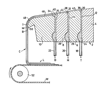
Figure 1 is a side cross-sectional view of a
photographic liquid coating slide hopper 2 in accordance
30 with the present invention. Slide hopper 2 includes
layering plates 4, 6, and 8 and curtain-forming plate
10. Layering plates 6 and 8 and curtain-forming plate
10 have upper planar surfaces 42, 44, and 46,
respectively, which together form a wide incline at an
-- ~ 2089963
-- 6
angle of from 5 to 20 degrees, preferably 15 degrees,
from horizontal. Protruding from the end of
curtain-forming plate 10 which is distal from the
layering plates is vertical lip 50.
The spaces between layering plates 4, 6, and 8
and between layering plate 8 and curtain-forming plate
10 form passages for supplying photographic liquids to
the incline formed by upper planar surfaces 42, 44, and
46. For top liquid T, this passage, which extends
10 transversely to slide hopper 2 ( e. into and out of
Figure 1), is defined by the space between layering
plates 4 and 6 and includes primary distribution
channel 24, metering slot 12, expansion section 30, and
discharge slot 36, all of which extend transversely of
15 hopper 2. Liquid T is fed to primary distribution
channel 24 by feed conduit 18 which has a central or
side location relative to the transverse extent of
channel 24 across the width of hopper 2. As to middle
liquid M, the space between layering plates 6 and 8,
Z0 defined by primary distribution channel 26, metering
slot 14, expansion section 32, and discharge slot 38,
all of which extend transversely across hopper 2,
constitutes the passage. Liquid M is supplied to
primary distribution channel 26 by feed conduit 20 which
25 is located centrally or at the end of the transverse
extent of channel 26. Bottom liquid B's passage is
between layering plate 8 and curtain-forming plate 10
and includes distribution channel 28, metering slot 16,
expansion section 34, and discharge slot 40, all
30 extending transversely of hopper 2. Feed conduit 22
supplies liquid B to primary distribution channel 28 and .
has a central or side location with respect to the
transverse extent of channel 28 across the width of
hopper 2. For liquids T, M, and B, the distribution
7 ~
'~
channels reduce the resistance to transverse flow of
liquid across hopper 2, while a high resistance to
longitudinal flow is maintained by metering slots. As a
result, liquid layers flowing onto the incline defined
5 by planar surfaces 92, 44, and 46 are spread to a
suitable width and have a high level of uniformity due
to the substantial reduction in pressure variation
achieved by the distribution channels. Instead of
providing each photographic liquid passage with a single
10 distribution channel, it is particularly desirable to
utilize a pair of serially-arranged distribution
channels (not shown) in each passage in accordance with
pending C~. Patent Application Serial No. 2,076,276 ,
entitled "Liquid Distribution System for Photographic
15 Coating Devices" to Solomon T. Korokeyi.
As is apparent from Figure 1, top liquid T is
discharged from discharge slot 36 onto planar surface
42. In turn, middle liquid M is deposited on and in
contact with planar surface 44 beneath top liquid T.
20 Likewise, bottom liquid B is deposited on and in contact
with planar surface 46 of curtain-forming plate 10
beneath middle liquid M and top liquid T. Once applied
to the incline defined by the upper planar surfaces of
layering plates 4, 6, and 8 and curtain-forming
25 plate 10, liquids B, M, and T maintain their identity as
separate and discrete layers.
The separate and discrete layers of liquids B,
M, and T flow down planar surface 46, around transition
section 48 and fall from lip 50 as a curtain C of liquid
30 coating onto web W as layer L. Web W is transported
into contact with curtain C by drive roller 52.
Figure 2 is a side cross-sectional view of the
liquid passage system between plates 8 and 10 of the
slide hopper of Figure 1. As depicted, metering slot 16
~ *-
,~. 5'i
~0~9~6~
-
-- 8
is defined by upstream wall 54 and wall section 56a
which are in parallel planes. Connected to metering
slot 16 is e~pansion section 34 which is also defined by
upstream wall 54 as well as wall section 56b. Discharge
5 slot 40, which receives liquid from e~pansion
section 34, is defined by wall section 56c and upstream
wall 54 which are in parallel planes. Liquid emerging
from discharge slot 40 onto upper planar surface 46 of
curtain-forming plate 10 forms a layer of bottom
10 liquid B. The liquid passage systems which form the
layer of top liquid T and the layer of middle liquid M
are similarly configured.
The angle ~ at which wall section 56b is
inclined from wall section 56a ranges from 5 to 45~,
1~ preferably 25O. The perpendicular distance between
upstream wall 54 and wall section 56a is 0.1 to 0.6 mm,
preferably 0.25 mm, and is substantially constant. The
perpendicular distance between upstream wall 54 and wall
section 56c is also substantially constant and ranges
20 from 0.5 to 1.5 mm, preferably 0.9 mm. The length of
wall section 56c between where it contacts wall
section 56b and upper planar surface 46 ranges from 1.5
to 4.5 mm, preferably 2.7 mm. To avoid low wall shear
stress and regions of flow recirculation, the location
25 where wall section 56a meets wall section 56b and where
wall section 56b meets wall section 56c are not defined
by sharp edges but, rather, by rounded transition
surfaces.
Figure 3 is a side cross-sectional view of a
30 second embodiment of a liquid passage system in
accordance with the present invention. This
configuration is essentially the same as that depicted
in Figure 2 except that the passage e~pands in the
upstream direction. As depicted, metering slot 16 is
~ -9-
defined by downstream wall 56 and wall section 54a.
Expansion section 34 is connected to metering slot 16
and is defined by downstream wall 56 and wall section
54b. From expansion section 34, liquid enters
discharge slot 40 which is defined by wall section 54c
and downstream wall 56. As in Figure 2, liquid
emerging from discharge slot 40 flows onto planar
surface 46 of curtain-forming plate 10 as a layer of
bottom liquid B.
The angle ~' at which wall section 54b is inclined
from wall section 54a ranges from 5 to 45, preferably
25. The perpendicular distance between downstream wall
56 and wall section 54a is 0.1 to 0.6 mm, preferably
0.25 mm, and is substantially constant. The
perpendicular distance between downstream wall 56 and
wall section 54c is also substantially constant and
ranges from 0.5 to 1.5 mm, preferably 0.9 mm. The
length of wall section 54c between where it contacts
wall section 54b and upper planar surface 44 ranges
from 1.5 to 4.5 mm, preferably 2.7 mm. Like the
embodiment of Figure 2, wall sections 54a, 54b, and 54c
are joined by rounded transition surfaces.
Figure 4 is a side cross-sectional view of a third
embodiment of a liquid passage system in accordance
with the present invention. This arrangement, in
essence, combines the features of Figures 2 and 3.
Metering slot 16 is defined by wall sections 54c and
56c, expansion section 32 is formed by wall sections
54b and 56b, while discharge slot 40 is defined by wall
sections 54a and 56a.
The angles ~ and ~' are 2.5 to 22.5, preferably
12.5. The perpendicular distance between wall sections
54a and 56a is 0.5 to 1.5 mm, preferably 0.9 mm, and is
substantially constant. The perpendicular distance
between wall sections 54c and 56c
A
--10--
is 0.1 to 0.6 mm, preferably 0.25 mm, and is
substantially constant. The length of wall section 56c
between where it contacts wall section 56b and planar
surface 46 and of wall section 54c between where it
contacts wall section 54b are both 1.5 to 4.5 mm,
preferably 2.7 mm. As in the embodiments of Figures 2
and 3, rounded transitions connect wall sections 54c
and 56a-c.
Metering slots 12, 14, and 16 must be configured
to hold an upstream backpressure so that liquid will
spread transversely through distribution channels 24,
26, and 28, respectively, and nonuniformities can be
removed. The discharge slot is of sufficient length
and width to prevent vortex formation on the slide
surfaces and intermixing of coating layers above the
discharge slot.
The liquid passage system of the present invention
has numerous advantages over prior art arrangements.
It is able to handle liquid flowing at Reynolds Numbers
of up to 50 without substantial vortex formation in the
liquid passage system or on the downstream planar
incline. This system is also able to operate without
substantial interlayer mixing at similar Reynolds
Numbers. The present invention also utilizes an
economical and simplified structural arrangement.
Moreover this arrangement can easily be retrofitted to
existing coating hoppers like those disclosed by U.S.
Patent No. 3,005,440 to Padday.
Although the invention has been described in
detail for the purpose of illustration, it is
understood that such detail is solely for that purpose,
and variations can be made therein by those skilled in
the art without departing from the spirit and scope of
the invention which is defined by the following claims.
~ 1 .