Note: Descriptions are shown in the official language in which they were submitted.
W093/00780 PCT/GB92/~1147
~9010~
ELECTRIC ELEMENT ASSEMBLY
This invention concerns an electric elemQnt
assembly for liquid heating purposes, particularly but
not exclusively for an electric kettle.
Conventionally, an electric kettle element
assembly, of the type with which the present invention
is concerned, comprlses a substantially flat metal
backplate and a metal-sheathed reslstance heating
element which extends from and has lts ends seallngly
connected to the backplate, with a central portion of
the sheath also in dlrect thermal transfer relation with `
the backplate. In use, the backplate ls sealed relatlve
to an aperture in the kettle wall, with the element
extendlng lnto the llquld reception vessel.
The reason for having the central portion of the
sheath ln dlrect thermal transfer relatlon with the
backplate ls to effect rapid heat transfer through the
backplate to a temperature sensitive cut-out (usually a
bimetalllc strip, but possibly a plastics strlp)
dlsposed at the other side in the event that the element
is operated when not immersed in liquid, so as to cut
off power supply to the element before too much damage
is done.
The backplate and the element sheath ar~
conventionally formed of copper or an alloy of copper,
which are good heat conductors. ~owever, stalnless
steel ls increasingly popular since, despite having
poorer conductlvlty, lt has the advantage that lt does
not discolour over a period of use in bolllng water.
, .
Conventionally, the ends (legs) and central
portion of the element sheath have been connected to the
backplate by brazing. Thls involves applying a jointing
or "brazing" material, such as a copper alloy, (in the
.. : ~. ..
,
'' " ' ' ~,"' ' ;
`, . ~ ~ ' ' ' `
W093/00780 PCT/GB92/01l47
~09~i1()~ 2
manner of a glue) between the regions to be connected
and then placing the entire subassembly in a furnace to
heat all the material sufficiently to melt the brazing
material, and form an effective joint. This would
usually be done in two stages, firstly to connect the
central element sheath portion, then to connect the
legs. Brazing is imprecise, messy and costly and is
best avoided as part of a manufacturing process.
Moreover, in the case of stainless steel, higher
temperatures are required to produce effective joints by
brazing so a higher cost is involved in having to
install, or adapt, and run a furnace for higher
temperature operation in addition to the general
difficulty of automating any brazing procedure~
In their earlier applications Nos~ 91 02915 and
91 02883 the applicants set forth proposals for avoiding
any brazing process in production of the relevant type
of electric element assemblies by making special
provision for welding a central region of the element
sheath to the backplate and by connecting the ends of
the element sheath to the backplate in various
different ways~
The object of the present invention is to propose
novel electric heating assemblies which avoid the need
to connect a central portion of the element sheath to
the backplate, by brazing or otherwise, by providing
alternative means for actuation of a temperature
sensitive cut-out.
According to a first aspect of the invention an
electric element assembly for liquid heating purposes
comprising an element, in the form of a resistancè
heating wire disposed within a metal sheath and
connected to pins which project from respective ends of
the sheath, is chàracterised by having temperature
sensitive cut-out means mounted in thermal transfer
... . . . .
,..... : '
W093/00780 PCT/GB92/01147
3 '~ 0~
relationship with the element sheath at one end thereof.
In practical embodiments in accordance with this
first aspect of the invention the temperature sensitive
cut-out means is conveniently connected to a sleeve or
liner of thermally conductive material which is fltted
into the element sheath in thermal transfer
relationship with the inner surface of the sheath.
Provision of such a sleeve or liner intermediate the
sheath and the cut out means is especially desirable
when the sheath itself is of steel and of relatively
poor thermal conductivity.
Such a sleeve or liner may be a simple friction
fit in the sheath or it may be spot welded to the
sheath.
According to a second aspect of the invention an
electric element assembly for liquid heating purposes
comprising an element, in the form of a resistance
heating wire disposed within a metal sheath and
connected to pins which pro~ect from respective ends of
the sheath, is characterised by having temperature
sensitive cut-out means mounted in thermal transfer
relationship with a sleeve of thermally conductive
material which is inserted into one end of the sheath.
In practical embodiments in accordance with this
second aspect of the invention the sleeve need not be
mounted in contact with or in thermal transfer
relationship with the inner surface of the sheath. The
cut-out arrangement could work satisfactory with a layer
of insulating material between the sleeve and the
sheath, in which case the sleeve may be mounted simply
by being embedded in insulating material within the
sheath.
Thus, when an element in accordance with either
:, ~ '
. ' '
.
W093/00780 PCT/GB92/01147
'~u~ 4
aspect of the invention is mounted onto a backplate by
the sheath extending through and being sealingly
connected to the backplate adjacent its ends, there is
no longer any need for intimate contact between a
central portion of the element sheath and the backplate.
Brazing can be completely eliminated from the
manufacturing procedure by not effecting any connection
of the central portion to the backplate and by using
other connection means, such as sealing rings held by
frictionally engaged discs for connection of the legs of
the sheath through apertures in the backplate. In this
respect, various connection means for the legs which
avoid brazin~ are described in more detail in the
applicant's earlier UK application No. 9l 0~915~
Copper is a suitable material for the sleeve or
liner within either aspect of the invention.
The terms sleeve or liner as used within this
specification are intended to refer to members which,
whilst not necessarily completely surrounding or
encircling respective conductive pins, at a spacing
therefrom, extend at least part way around said pins,
usually around a major part. Thus the terms sleeve or
liner include slotted or perforated members as well as
simple cylindrical members. These need not be mounted
concentrically of the element shea~h or the respective
pin, although they will most usually be so mounted.
Furthermore, the sleeve or liner may conveniently
be formed of two or more separate pieces or fixed `
adjacently. A gap between such adjacent pieces can form
the slot or perforation when required.
In embodiments within the first or second aspects
of the invention, to facilitate connection to the cut-
out means a portion of the sleeve or liner preferably
projects beyond the end of the sheath.
W093/00780 PCTtGB92/01147
2~)9~ 06
The pins, which project from the sheath and to
which the resistance heating wire is connected, are
traditionally of poor thermal conductivity, being
merely required to be good conductors of current between
the heating wire and electric power supply connections
at the opposite side of the backplate. In this respect,
the usual material for those pins is steel.
Thus, in order to maximise heat transfer from the
resistance heating wire to the cut out means, in
embodiments within the first or second aspects of the
invention the sleeve or liner may advantageously extend
into the sheath a sufficient distance to surround a
portion of the resistance heating wire, ad;acent its
connection to the inner end of the respective pin. Heat
will then be conducted from the wire to the sleeve or
liner by way of any intermediate electric insulating
material, such as magnesium oxide, in which the wire is
embedded.
Of course, in embodiments where the sleeve or
liner is connected to or in contact with the sheath, and
particularly where the sheath is a good heat conductor
(i.e. of copper), heat will also be transmitted to the
sleeve or liner by conduction from the sheath. In such -
embodiments, but also in others, the cut-out arrangement
may still operate satisfactorily when the sleeve or
liner simply surrounds a part of the pin and stops short
of the wire or the region where the pin connects to the
wire~ ~
, ,
The temperature sensitive cut-out means within
either aspect of the invention is conveniently a
conventional bi-metallic strip, which bends upon heating
and thereby breaks the circuit whereby power is supplied
to the element by way of the pins. The alternative of a
plastics cut-out means is also possible, but unlike a -
bimetallic strip, it does not provide for reversible
.. , ' ? ' ~ ~ ,
:
.: , . .::
W093/00780 PCT/~B92/01147
~ U 6
operation (it disintegrates upon overheating) so it is
only useful as an ultimate fail safe to prevent complete
burn out of an appliance.
The invention also provides an electric element
for liquid purposes comprising an element in the form of
a resistance heating wire disposed within a metal sheath
and connected to pins which pro;ect from respective ends
of the sheath, characterised in that a sleeve or liner
of thermally conductive material is fitted into the
lement in thermal transfer relationship with the inner
surface of the sheath.
In a further aspect, the invention prov~des an
electric element for liquid heating purposes comprising
an element in the form of a resistance heating wire
disposed within a metal sheath and connected to pins
which project from respective ends of the sheath,
characterised in that the element includes a sleeve or
liner of thermally conductive material which is inserted
into one end of the sheath, which sleeve or liner is
adapted to engage temperature sensitive cut-out means in
a thermal transfer relationship.
The invention will be explained further by way of
further example, with reference to the accompanying
drawings, in which:
Fig. l is a schematic illustration of connection
of a bimetal to a sheath of a heating element by way of
a sheath liner in accordance with the first and second
aspects of the present invention;
.
Fig. 2 is a comparable illustration of connection
of a bimetal to a separate sleeve inserted into the
sheath in accordance with the second aspect of the
present invention; and
..'
W093J007~0 PCT/CB92/01147
7 ~ 0 6
Fig. 3 is a part sectional view of an electric
element assembly fitted to an electric kettle.
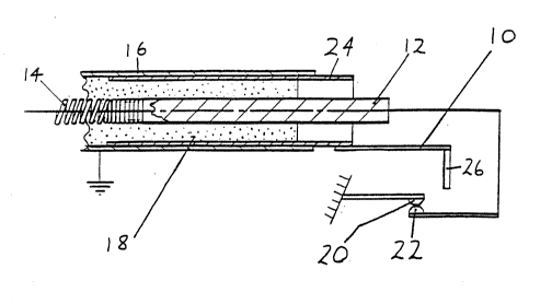
Fig. 1 shows one end of an electric element as
used in a kettle. A pin 12 is connected to one end of a
coiled resistance heating wire 14 of any conventional
material, such as an alloy including any of nickel,
chromium, iron and aluminium. The coiled wire 14
extends through a tubular sheath 16 of stainless steel
or copper but is electrically insulated therefrom by a
packing 18 of magnesium oxide or other suitable
material. The pin 12 projects from the end of the
sheath 16 and is similarly electrically insulated
therefrom. A seal or plug (not shown) may also be
provided outwardly of the insulating material.
At its other end the wire 14 is connected to
another pin (not shown) which projects from the other
end of the sheath 16 in similar manner.
In use, a voltage is applied to the wire 14 via
the pins. Owing to its resistance, the wire 14 heats
up. The surrounding sheath 16 also heats up and
transfers heat to its surrounding medium. In this case,
the element is designed as a kettle element for
immersion in water to boil the water.
A bimetal strip 10 is connected to the element
sheath 16 by way of an additional sleeve 24 which is
mounted inside the end margin of the sheath 16, for ~ `
example as friction fit therein or by spot welding. The
sleeve 24 is inserted into the sheath 16 a sufficient
distance to surround an end portion of the wire 14,
where the latter connects to the inner end of the pin
12, and also projects from the sheath 16 concentrically
of the pin 12. The sleeve 24 should have good heat
conductivity. It may be of copper or any suitable
alloy.
,.:. .
. . ,. ! ~, , ' ~: ' :,
~ ' . . '
W093/00780 PCT/GB92/01147
2~90~06 8
The sheath 16 is not a current carrier
(diagrammatically represented by earth symbol) so there
is no conduction of electricity to or through the
bimetal lO, which, consequently, is not part of the
power supply circuit. The bimetal lO may suitably carry
a finger 26 of insulating material whereby contacts 20,
22 in the power supply circuit to the pins 12 will be
broken upon deflection of the bimetal lO.
Heat is conducted from the sheath 16 to the
bimetal ~0, by way of the sleeve 24, much faster when
there is no water surrounding the sheath 1~ to take up
the heat generated by the wire 14. Thus, under dry
operation, the bimetal lO rapidly reaches a temperature
of about 125 where it deflects and breaks the power
supply circuit. While the element is immersed`in water,
the temperature rise of the bimetal is slower and it
will not ~each a temperature sufficient to cause
breaking of the circuit.
In other respects the manner of operating is
readily apparent to those skilled in the art.
It is to be emphasised that the foregoing is only
one example of an arrangement within the scope of the
invention.
In accordance with the first aspect of the
invention the use of an intermediate sleeve may be
dispensed with~ Thus, whilst use of an intermediate
sleeve of high thermal conductivity is highly
advantageous in cases where the sheath itself is of
steel, and therefore not a particularly good heat
conductor, in cases where the sheath is of copper the
bimetal may suitably be connected directly to one end
of the sheath, or connected thereto in some other
manner.
- . ,:: ~ , . .
,: ' ,`, ;. :
--. : . :
- . . ,. .:, . .
:, ~
W093/00780 PCT/GB92/01147
9 2~9010~
Fig. 2 shows an alternative arrangement, in
accordance with the second aspect of the invention. The
same reference numerals as in Fig. 1, but with suffix ',
have been used to designate parts which are equivalent
to those in Fig. 1 so that repetition of their basic
description need not be repeated.
In this embodiment the bimetal strip lO' is again
connected to the thermally conductive sleeve 24', but
the latter is neither connected to nor in contact with
the element sheath 16'. Thus, the bimetal 10' is not
necessarily in thermal transfer relationship with the
sheath 1~` and, particularly where the latter is of a
poor thermally conductive material, such as steel, the
majority of the heat transferred to the bimetal 10' by
the sleeve 24` is derived by conduction through the
insulating material 18' from the wire 14`, and the pin
12'. In other respects, operation is precisely the
same as in Fig. 1.
It should be pointed out that Fig. 2 is only one
example of an arrangement within the scope of the second
aspect of the invention. In other embodiments, the
sleeve may be in contact with the sheath, exactly as in
Fig. 1. -
~ ..
Whichever type of arrangement is employed -
direct connection of a bimetal to the element sheath, or
connection of a bimetal to the sheath by way of a
thermally conductive sleeve, as in Fig. 1, or connection
of a bimetal to a sleeve which is quite separate from
the sheath, as in Fig. 2 - respective bimetal cut-out
arrangements may be provided at each end of the
element, as a fail safe measure. Also, in all cases,
cut-out means other than a bimetal strip may aLso be
empioyed, the principle remaining the same, except that
with plastics cut-out fuses, the cut-out is not
reversible as the fuse disintegrates and has to be
W093/00780 PCT/GB92/01147
~g~o~ 10
replaced be ore the element will operate again.
Fig. 3 shows a first aspect o the invention
generally according to Fig. 1, as fitted to an electric
kettle 30. It will be seen that the element sheath 16
is arranged in a substantialy planar configuration in a
kettles bottom 32. The arrangement may be as a coil or
as to ad;acent loops or any other convenient
configuration. Both ends of the sheath 16 are sacured
in a housing 34 which passes through the kettles
sidewall 36 and is sealed thereto by a peripheral
sealing ring or grommet 38.
The housing 34 serves to retain the bimetallic
strip 10, the connected finger 26 and the various
electrical components including the contacts 20, 22 etc
and is sealed to prevent any water entering therein.
THe housings exterior 40 provides an electrical
connection point for the application of a voltage to the
wire 14 enclosed in the sheath. It is also possible to
provide two sleeves 24 one at each end o the wire 14
where it connects with the electricity supply.
~ : -
- : , ~
: ,: ., :-
.. - .
:.. ~:: .' - -