Note: Descriptions are shown in the official language in which they were submitted.
W093/0~3 PCT/US92/05303
_ I _
20902~2
APPARATUS AND METHODS FOR CUTTING SOIL AND IN SITU
CONSTRUCTION OF SUBSURFACE CONTAINMENT BARRIERS
This invention relates generally to apparatus and
methods for cutting soil and constructing subsurface
containment barriers in place Although not necessarily
limited to the following, the present invention has
particular application in simultaneously cutting through
a subsurface volume of 80il and emplacing a cement slurry
to construct in situ a continuous subsurface wall,
horizontal panel or basin around and under a hazardous
waste site
There are many automated ways of cutting or
excavating soil (soil as used herein refers to any ground
or sub6urface material to be cut or excavated) For
sxample, there are scooping devices such as backhoes and
cla~sh-lls; there are drilling devicea sUch ~8 augers;
and there are blasting devices such as dynamite and high
pre~ure fluid Of particul~r interest to the pre~ent
inv ntion as u-ed in the aforementioned exemplary
~pplic~tion, how v r, are the devices and techniques used
for cutting oil in the environmental remediation
industry
In the nvironmental remediation industry it i~
i oft-n d-sirable to form an impermeable underground
containment wall to contain contaminants which are
.~ .
..
,
- " ' ' ' '
- ~ .
.
WO 93/00483 PCT/US92/05303
20~242 -2-
present in the soil and water, thereby preventing or
impeding further migration of the contaminants.
Hazardous waste sites frequently contain hundreds of
thousands of cubic yards of materials which represent a
long term threat to ground water quality. While on site
treatment is a preferred means of eliminating this
threat, this is not always feasible. At some sites the
cost of physically removing the material and placing an
impermeable liner in the vacated cavity is beyond the
re60urces of the site owner. Sites with buried drums,
radioactive dusts, or other airborne hazards may become
much more dangerous if excavated. There are also cases
where vast and deep areas are only slightly contaminated
and require only a containment action. Existing
containment technologies provide the means to place a
wall around the perimeter of a site or to place a cap
over a site.
One common method of constructing a side containment
wall is by slurry trenching. This method digs a trench
and emplaces a bentonite (clay) slurry as the trenching
proceeds. Once the trench i~ dug, the slurry is replaced
with concrete or bentonite modified clay. This technique
tends to be slow And very costly at depths exceeding 40
feet. This technique is also limited to forming a
relatively wide (e.g., 36 inches) wall even though it is
only the thin filter cake build up on the wall that acts
as a peroeability barrier. The difficulties and expense
Or foroing and ensuring that a continuous wall has been
formed increas-~ dramatically below a 40 foot depth, a
d-pth below which this type of wall often needs to
ext-nd.
Hydraulic soil cutting using ~et grouting is another
t-chnigue u~ed in the environmental remediation industry.
Although this iB a useful technique, it is not
W093/00483 PCT/US92/05303
-3- 2090242
particularly efficient because much of the jet energy is
wasted in passing through fluid before impacting the
soil. This causes low production rates, and the cost of
the process tends to be higher than for mechanical
methods. In most forms of jet grouting it is also
difficult to verify that a continuous wall has been
formed because the wall is formed from a series of
overlapping columns rather than in a continuous fashion.
This makes it difficult to form containment walls deeper
than 40 feet using this technique.
For forming deeper walls, a four-auger drill system
and a clamshell digging tool have been used. The
four-auger system is very expensive and slow, capable of
lS forming only 20 to 30 linear feet of wall per day.
Clamshell excavating techniques are also very slow.
The foregoing techniques typically provide vertical
wall~. They do not typically provide bottom barriers
under the site, but rather they rely on having a natural
layer of low permeability soil (e.g., impermeable rock or
clay) underlying the waste site to complete the
containment envelope. We are, however, aware of two
prior ways of creating an underlying barrier.
Jet grouting technology a8 practiced by Halliburton
Services of Duncan, Oklahoma allows a bottom to be
in~talled by drilling vertical holes and using the ~et
grouting proc-~s to form overlapping disks of treated
mat-rial at the bottom elevAtion. Just as with side wall
~et grouting referred to above, it is difficult to verify
the integrity of the resulting underlying barrier.
Another technique u~es horizontal drilled holes with
liquid nitrogen freezing. This has quality control
problem6 and requireQ continuous ~aintenance. Ne~r
urface horizontal panc~ke fracturing or "block heavinq~
W093/0~3 PCT/US92/05303
2~9a2~2 _4_ ~~
is another technique which seems to work, but it is
difficult to control quality with this technique.
For very large sites containing enormous volumes of
waste such as are found in the mining industry for
example, the primary, if not the only, suitable technique
of waste containment of which we are aware is to
physically move the waste onto a synthetic liner and
place a cap over it. This has detrimental cost and
environmental impact shortcomings as referred to above.
Although the foregoing techniques may be effective
in particular applications, they have at least the
shortcomings noted above. What is lacking is a cost
effective technigue for cutting soil to facilitate at
least the deep construction of contaminated soil
impoundment walls and subsurface containment barriers
having high structural integrity around and under waste
~ite~ without moving the waste.
The present invention overcomes the above-noted and
other shortcomings of the prior art by providing a novel
and improved apparatus and method for cutting soil for in
situ construction of impoundment walls and/or ~ubsurface
containment barriers. The apparatus and methods enable
the faster, more efficient and more economical
con~truction of subsurface walls, ~uch as contaminated
~oil impoundment walls and containment barriers which can
xtend well below 40 feet into the earth.
In a preferred embodiment, the present invention
utilizes both hydraulic and mechanical excavation
technigues, but either one can be used alone. This
pr-ferred e~bodiment includes a long beam that is joined
by a hydraulic reciprocating m~mber to a pivot ~olnt on
the frame of a crane. Within the beam is a tubular
W093/00~3 PC~/US92tO~303
~5~ 2 0 ~ O ~ 4 2
conduit which conveys high pressure slurry from an
external mixing/pumping unit. At least a portion of the
conduit has a plurality of small holes or jet ports which
direct the ener~y of the high pressure slurry toward the
face of the soil to be cut. In this particular
embodiment the conduit is reciprocated lengthwise so that
the jets of slurry contact all the soil in tAe path of
each stroke.
The beam of this preferred embodiment is dense
enough so that it is not buoyant in any fluid or loose
mixture it might encounter. Accordingly, as each stroke
of the conduit is completed, the conduit's weight causes
it to sink or fall downward and forward to position
itself automatically for the next cut. As this occurst
the crane moves along the ground so that the advancing
conduit is pulled through an extended volume of soil
which is cut as the apparatus advances. These actions
maintain the jets positioned right at the face of the
20 80il to be cut; therefore, the pressurized fluid exiting
the jets does not have to pass through much if any
intervening fluid before it impacts the soil. Thus,
little energy is lost prior to impacting the soil.
In a preferred embodiment for forming a containment
barrier, the present invention uses reciprocating high
pressure jets of hardening fluid to cut through the soil
along a path from one side of a waste site to another
without passing through the waste material itself. As
the fluid cuts the soil, it also mixes with the soil and
~ubsequently hardens; thus, the high pressure jets, or
jet streams, provide both the necessary energy and
material for disrupting the soil and forming the barrier.
The path trAversed by the reciprocated jet is moved
transversely so that it passes under the site from one
end of the site to the other. As a result, an
w093/00483 P~T/US92/o53o3
2 ~ 4 ~ -6-
impermeable containment barrier sheet in the nature of a
basin is formed in situ both around and under the waste
site. The resulting barrier should have high structural
integrity because it is formed in a continuous manner.
It is also contemplated that this technique should be
cost effective for constructing in situ surface barriers,
or of partial containment barriers which prevent
underground contamination in moving in a particular
direction.
The present invention also provides a method of
cutting soil, comprising: generating cutting action along
an extended locus of soil; and advancing the cutting
action along a descending locus of the soil in response
to gravity. Generating cutting action can include
individually or in combination pumping a fluid through a
conduit having a plurality of ports through which the
fluid is ejected into the soil adjacent which the conduit
is disposed, reciprocating the conduit while pumping the
fluid, or reciprocating a beam along the extended locus
of 80il. The method can also comprise advancing the
cutting action horizontally from the descending locus.
The apparatus of the present invention can be used
for constructing a subsurface basin in soil. This
apparatus comprises means for creating in situ a
continuous cross-sectional portion of the subsurface
basin. The means includes a conduit adapted ~o be
disposed in the ~oil along at least a portion of a locus
extending into the soil from two locations at ~he upper
surface of the soil and lying across a cross-sectional
area of the basin. The conduit has at least one opening
for ejecting fluid under pressure into the soil. The
apparatus further comprises means for moving the conduit
tran~ver~ely to the locus.
W093/0~3 PCT/US92tO5303
-7- 2~9~2~2
The present invention provides an apparatus
particularly suitable for constructing a containment
barrier around and under a waste site disposed in soil,
which apparatus comprises: means for cutting a continuous
elongate trench through the soil under the waste site and
preferably from one side of the waste site to another
side of the waste site without intersecting the waste
site; means for displacing the means for cutting through
the soil 80 that the elongate trench is extended
transversely to itself across a continuum along and under
the waste site; and means for placing a barrier material
in the transversely extended elongate trench.
The present invention also provides a method of
constructing a subsurface barrier, which method
comprises: (a) cutting into soil along a continuous locus
extending into the soil from two locations on the surface
of the ~oil; (b) simultaneous with step (a), emplacing a
fluidized barrier material-in the cut soil; and (c)
repeatinq steps (a) and (b) throughout a continuum
between a first such locus and a second such locus.
Therefore, from the foregoing, it is a general
object of the present invention to provide a novel and
improved apparatus and method for cutting soil for
constructing in situ impoundment walls and containment
barriers. Other and further objects, features And
advantages of the present invention will be readily
apparent to those skilled in the art when the following
de~cription of the preferred embodiments is read in
conjunction with the accompanying drawings.
FIG. 1 is a schematic diagram of a preferred
embodiment of the present invention.
W093/0W83 PCT/US92/05303
209~2~2 -8-
FIG. 2 is an illustration of a particular
implementation of the apparatus represented in FIG. l.
FIG. 3 is a perspectiv~ view of a preferred
embodiment of a portion of a beam and conduit of the
particular implementation shown in FIG. 2.
FIG. 4 is a side view of hydraulic cylinders
connected to the beam for reciprocating the beam and the
conduit mounted on the beam.
FIG. 5 is another side view, partially in section as
marked by line 5-5 in FIG. 4, of the hydraulic cylinders
shown in FIG. 4.
FIG. 6 is a cross-sectional illustration of a
multiple beam assembly which can be used in the apparatus
illustrated in FIG. 1.
FIG. 7 i8 a schematic illustration of a beam and
conduit assembly wherein only the conduit is reciprocated
as the beam and conduit advance through the soil.
FIG. 8 is a schematic perspective view of a
containment barrier basin of a type contemplated to be
formed with the present invention.
FIG. 9 is an illustration of a particular
implementation of the present invention suitable for
constructing the barrier illustrated in FIG. 8.
FIG. I0 is a perspective view of a preferred
embodiment of a fluid jetting and support structure more
generally shown in FIG. 9.
WO 93/00483 PCT/US92/05303
9 20902~2
FIG. 11 is an iliu~tration of another particular
implementation of the present invention.
FIG. 12 is an illustration of a further particular
implementation of the present inventicn.
FIG. 13 is a sectional view, as taken along line
13-13 in FIG. 12, of a conduit and stabilizer of the
implementation shown in FIG. 12.
FIG. 14 is an illustration of a preferred embodiment
for cutting soil and forming subsurface containment
barriers.
FIG. 15 is an illustration of the pivot point
between the beam and boom of FIG. 14.
- FIG. 16 is an illustration of the jet port area of
FIG. 14.
FIG. 17 is an illustration of the end jet port area
of FIG. 14.
.
Referring to FIG. 1, the present invention broadly
includes means for abutting soil 2 in response to
gravity, and means, connected to the means for abutting,
for creating a cutting action sgainst the abutted soil.
The means for abutting of the embodiment depicted in FIG.
1 includes a falling beam 4 which is shown pivotally
conn-cted to a support 6 on the surface of the soil 2;
however, the means for abutting can be implemented in
other ways a~ will be further referred to hereinbelow.
The means for creating a cutting action can also be
impl~mented in any of various different ways. One of
t~e~e includes a source of pressurized fluid ~
represented in FIG. 1. Presently contemplated
w093/00483 PCr/US92/05303
--10--
2 ~ 4 2
implementations of these elements will be further
described hereinbelow.
The equipment shown in FIG. 2 is a particular
implementation of the apparatus represented in FIG. 1.
The beam 4 (see also FIG. 3) is a linear series of
inter~onnected H-shaped steel m~mbers 10. Steel plates
12 are bolted to adjacent members to hold them together.
This permits on-site fabrication of selected lengths of
beams. The me~bers 10 are intrinsically heavy enough or
are filled in a central cavity with a weight-increasing
material (e.g., high density concrete 14 as illustrated
in FIG. 3) to ensure that the beam 4 automatically sinks
in response to gravity as the soil 2 is cut. More
generally, the beam 4 is constructed so that it is not
buoyant in any fluid or loose mixture it encounters as
the 80il 2 is cut in accordance with the present
invention. FIG. 2 shows the beam 4 adjacent face 16 of
initially uncut soil 2a after the apparatus has passed
through cut soil 2b due to the cutting action and
automatic advancing of the present invention.
The beam 4 of the FIG. 2 embodiment has opposed
channels 18, 20 (see FIG. 3). A conduit 22 of the means
for creating a cutting action is supported by the beam 4
in these channels as shown in FIG. 3. The conduit 22
includes tubular members having a plurality of small
(e.g., about 2 to 6 millimeter) ports or jets 24 along
the portion of the conduit 22 facing the soil 2. The
conduit 22 conducts fluid under high pressure from the
source 8 to the jets 24 so that the fluid is ejected from
the jets at high velocity to cut the soil impacted by the
fluid. An example of a particular fluid source 8
includes a known type of cement mixing and pumping truck
26 receiving bulk materials in a known manner from a
trailer 28 (such a truck and trailer can be provided by
W O 93/004X3 PC~/US92/05303
209024~
Halliburton SerYices of Duncan, Oklahoma). A fluid
circulating circuit is formed hy connecting the two ends
of the conduit 22 to two hoses 30, 32 from the truck 26
as depicted in FIG. 2.
When the fluid pumped into the soil is a cement
slurry, a continuous subsurface wall is constructed
throughout the traversed volume simultaneously with the
cutting action. That is, as the cement slurry exits the
ports or jets 24, it cuts the soil and mixes with it, but
this mixture is retained in place by the adjacent uncut
soil outside the path of the beam 4. Upon curing or
hardening of this mixture, the continuous subsurface wall
provides a containment barrier such as for contaminated
material buried in the adjacent uncut soil.
It is contemplated that the high pressure fluid
alone can be sufficient to produce enough cutting action
for the beam and conduit ta advance into the soil. It is
also contemplated that additional means can be u~ed. For
example, the beam could be vibrated or other mechanical
technigues could be used to generate or facilitate the
forward motion of a thin subsurface member. The
preferred embodiments of the present invention include
means for reciprocating the conduit 22 so that the jets
24 are moved bac~ and forth across the soil to be cut.
This means can be implemented either to reciprocate both
the beam 4 and the supported conduit 22 relative to the
oil or to reciprocate the conduit 22 relative to both
the beam 4 and the soil 2. An illustration of t~e former
iB ~hown in FIGS. 2, 4 and 5, and an illustration of the
latter i8 shown in FIG. 7.
The reciprocating means of FIGS. 2, 4 and 5 includes
a hydraulic cylinder assembly 34 having one end connected
to the beam 4 and having its other end connected to the
W093/00~3 rCT/~S92/0~303
-12-
299~242
frame of a crane 36 embodying the support 6. These
connections can be by any suitable means known in the
art, but in the illustrated embodiment the end connected
to the crane 36 is connected by means of a trunnion 38.
The hydraulic assembly 34 includes two hydraulic
cylinders 40, 42 and a centering box slide with wear
plates collectively marked with the reference numeral 44.
The cylinders 40, 42 are operated from the cab of the
crane 36 through hydraulic control lines 45. This
control extends and retracts the cylinders through
whatever length of stroke for which the cylinders are
designed (e.g., 5 feet to 20 feet). The beam 4 and its
mounted conduit 22 follow this movement to stroke along
the adjacent soil. This ensures complete coverage of the
soil by the jets 24 and their ejected high pressure
fluid.
An alternative to the foregoing embodiment of the
reciprocating means is illustrated in FIG. 7. In FIG. 7,
the beam 4 is not reciprocated (but it is still free to
pivot where it is attached to the support 6), but the
conduit 22 and its jets 24 are moved back and forth along
the beam 4 and the adjacent soil. The conduit 22 can be
mounted on pulleys 46 to facilitate its movement. The
ends of the conduit 22 are mounted on reels 48, 50 which
are operated by a controller 52. The controller 52 can
be implemented in a known manner to synchronize the reels
48, 50 and the back and forth movement of the conduit 22.
Groups of jets 24 are spaced to accommodate the stroke
length of the back and forth movement so that the entire
so~l area adjacent the length of the beam 4 is covered
during each reciprocation. Fluid is communicated into
t~e conduit 22 by the hoses 30, 32 connected in a known
manner with the ends of the conduit 22 on the reels 48,
50.
- :,
W093/0~3 PCT/US92/05303
209~2~2
-13-
The embodiment illustrated in FIG. 7 can be
implemented in other ways. Steel or other suitable
material cables connected to the conduit 22 can be
mounted on the reels 48, 50 so that the reels wind and
unwind the cables to move the conduit 22 rather than
winding and unwinding the conduit ends directly. In an
alternative embodiment, the high pressure fluid can be
provided through a flexible hose contained within the
interior cavity of the beam 4 filled with a dense fluid
to allow movement of the hose and give sufficient weight
to the beam 4 to prevent it from having buoyancy.
The means for creating cutting action of the
embodiment shown in FIGS. 2-5 further includes one or
more mechanical cutter members connected to the beam 4.
One type is shown in FIG. 3. This type includes a
plurality of serrated blades 54 pivotally connected to
the beam 4. Another type is illustrated in FIGS. 2 and
5. This type includes a plurality of saw teeth 56
connected to the beam 4. As u~ed herein, "connected to"
includes being formed as an integral part of t~e beam 4
or other object. Regardless of the particular manner in
which the mechanical cutter members are implemented, they
are preferably disposed to cut a path at least sliqhtly
wider than the main body of the beam 4 to facilitate
movement of the beam 4 through the cut soil.
A~ proviously described, movement of the beam 4
occur~ at l-ast in response to gravity as the beam 4
sinks into ths cut, fluidized soil. In the illustrated
~bodiment, the beam 4 i~ also moved by the ~upport 6
dhown in FIG. 2 specifically implemented by a
conventional crane 36. As the crane 36 moves to the
right as viewed in FIG. 2, it advances the be~m 4 and the
conduit 22. Thi5 i~ done even while the beam 4 and/or
conduit 22 are being reciprocated. Referring to FIG. 1,
W093/00~3 PCT/US92/05303
~ 242 -14-
gravity can move the beam and conduit through sector 58
of the soil 2, and a mobile support 6 can move them
through the volume which includes the area 60. In
practice the beam and conduit typically will be
transported by the support 6 so that an acute angle 62
(e.g., 45 degrees) to vertical is maintained.
In the FIG. 2 embodiment, a line 64 from the crane
36 implementing the support 6 is connected to the beam 4.
The line 64 is typically slack during operation of the
apparatus, but it can be used to lift the beam and
conduit assembly if desired.
Although the support 6 is used in the preferred
embodiments described herein, it is contemplated that it
is not required. That is, it is contemplated that the
beam and conduit can be used without the support 6 when
sufficient cutting action can be obtained with the high
pressure fluid alone. For example, a beam of desired
length can be laid along the ground and high pressure
fluid pumped through the ports of the conduit to create
the cutting action. As this occurs, the beam and conduit
will sink. If the fluid is a cement slurry, for example,
a wall will be constructed above the sinking beam and
conduit. When the beam and the conduit are at the
desired depth, pumping is stopped and the hoses extending
into the ground to the ends of the conduit are cut or
otherwise disconnected. The beam and the conduit are
left in the ~oil at the bottom of the wall.0
lt is to be noted that "beam" as used in the
foregoing and other embodiments described herein can in
general be anything which advances into the cut soil to
recain adjacent the face of initially uncut 80~ 1 in
response to gravity. Thi6 includes 'he previously
described B-beam structure, but it includes other
W093/0~3 PCT/US92/05303
-15- 2~90242
embodiments as well. It is contemplated that the "beam"
can be implemented by a flexible member, such as a hose,
which is made rigid by the fluid pumped through it. The
material of the flexible member and the composition of
the fluid should be such that their combined weight is
sufficient to make this form of beam sink or advance in
the needed manner. This latter type of beam would thus
implement both the beam and the conduit. Another form of
initially flexible beam can include concentric hoses or
members. The inner structure would be filled with any
needed weight-increasing material, and the annulus formed
between the inner and outer members would conduct the
high pressure fluid to be ejected through the ports or
jets in the outer member.
Additionally, a "beam" as used herein can include
multiple components. This refers not only to multiple
pieces as the segments 10 and plates 12 shown in FTG. 3,
but also to multiple overall beam structures. For
example, two beam structures are represented in FIG. 6.
Each of these is similar to the beam 4 of the embodiment
described hereinabove with reference to FIGS. 2-5. The
two beams 4a, 4b of FIG. 6 are connected to respective
reciprocating means at the surface (not shown, but these
can be the same as the hydraulic cylinder assembly shown
in FIGS. 4 and 5). The lower, free ends of the be~ms 4a,
4b are linked by a sliding link 66 to prevent these lower
ends from moving laterally sway ~rom each other as the
bsam~ advance into the 80il. The illustrated link 66 is
implemented by a pin 68 connected to the beam 4b and
pasfiing through a ~lot ~0 formed in the beam 4a. This
construction is contemplated to be analogous to the
oppositely reciprocated blades of an electric knife.
Additional ~e~ms can be used. The number is conte~plated
to depend on the desired width of the cut to be made
l~.g., 12 inches or greater).
w093/004x3 -16- P~/US92/05303
~ V 9 ~
Referring to FIG. 2, the operation of the embodiment
shown therein will be described. The operation of other
embodiments described hereinabove will be readily
apparent from the following description as well as from
the descriptions given hereinabove.
The apparatus shown in FIG. 2 can be transported to
a site in modular sections, such as 401 H-shaped beam
sections and suitable lengths of conduit sections. The
beam and conduit can be assembled at the site to the
desired length (e.g., 401-1501 as can be suitable for a
contaminated material containment wall). A shallow
(e.g., 31 deep) pilot trench 72 is cut in a known manner,
and the assembled b am and ~onduit are laid in it. The
fluid is made and pumped from the vehicles 26, 28, and
the fluid is injected into the soil through the jets 24.
The beam 4 and/or the conduit 22 are reciprocated. As
this occurs, the beam and the conduit descend as the soil
beneath them is liquefied if the ejected fluid is liquid.
The crane 36 moves to advance the subsurface structure.
If the fluid is a cement slurry, the liquefied ~oil will
harden to form a wall, such as a low permeability cut off
wall for impounding contaminated subsurface material.
Any suitable fluid can be used. For example, various
admixes can be used to impart plasticity or chemical
resistance to the final material. Specifically regarding
material for constructing a subsurface containment wall,
examples of fluid~ include cement slurry, latex polymer
cement, bentonite clay slurry, hot wax, hot asphalt, hot
polyethylene or gelled water. - Other things can be
emplaced with the present invention, such as a drain pipe
for use as an intercepter of leaching contaminants.
The high pressure water, mud, cement slurry or other
fluid is ejected from the jets 24 so that the resultant
kinetic energy disrupts and erodes t~e soil into finely
W093/0~3 2 0 ~ 2 PCT/US92/05303
17-
divided particles which are intimately mixed with t~e
jetted fluid. The jetted fluid d~es not have to pass
through much intervening fluid or material in the
preferred embodiments so that little of the kinetic
energy is lost before it impacts the soil. ~his is
accomplished by the continuous advancement of the
subsurface structure in response to gravity whereby the
beam and the conduit are maintained against the face 16
of the initially uncut soil 2a. In a particular
implementation of the preferred embodiment, the jets 24
are kept within about 4 inches of the face 16. This
closeness is important because the kinetic energy of the
fluid diminishes roughly proportional to the square of
the distance in inches between the jets and the soil.
Once a desired length of subsurface volume has been
cut, a turn such as a right angle corner can be made by
allowing the subsurface structure to fall to a near
vertical position or by removinq the subsurface structure
from the ground and intersecting the previous cut.
From the foregoing, the method of the foregoing
preferred embodiments broadly comprises generating
cutting action along an extended locus of soil; and
advancing the cutting action along a descending locus of
the 80il in response to gravity. Generating cutting
action includes pumping a fluid through the cond~it 22
having the plurality of ports 24 through which the fluid
i~ ejected for injection into the soil adjacent which the
conduit is di~posed. If the fluid is a cement slurry, for
example, the fluid injected into the soil forms a wall
throughout the locus traversed by the cutting action. As
the fluid leaves the jets, its high pressure is converted
to kinetic energy to cut the soil and mix with the
resulting particles to produce a fluidized mixture. The
cutting action is achieved by reciprocating the jets or
W0~3~0~483 PCT/~S92/05303
-18-
2Q~3~32~
the entire conduit 22 while pumping the fluid.
Reciprocating the conduit can be a~complished by moving
the beam 4 with the conduit 22 or by moving the conduit
22 relative to the beam 4. In either case, the ports 24
of the conduit 22 are moved along the locus of soil to be
cut so that the ejected fluid impacts across the
initially uncut face 16 of the soil.
A new initially uncut face 16 is continually
encountered because the method of ~he foregoinq preferred
embodiments includes the aforementioned step of advancing
the cutting action. In these preferred embodiments this
includes pivoting the beam 4 through a sector which can
be part or all of the sector 58 depicted in FIG. 1. The
beam 4 pivots at the point or points of connection to the
support 6, and it pivots from its initial placement along
a length of soil such as in the pilot trench 66.
Pivoting occurs downwardly from this position in
automatic response to gravity as the underlyinq 80il is
cut and fluidized. In the preferred embodiments, the
method also includes advancing the cutting action
horizontally from the descending locus and sector 58,
such as by pulling t~e beam 4 horizontally with the crane
36.
The following examples provide a comparison between
a conventional jet grouting technique and the invention
of FIGS. 1-7 as a means of estimating the production rate
of such invention.
Examp}e I
Jet qrouting data supplied by Halliburton Services
indicate that a pair of 2 millimeter diameter jets on a
rotating 2 inch diameter shaft can produce a 12 inch
diameter column at a rate of 2 seconds of dwell for each
W093/0~3 2 0 ~ 0 2 4 PCT/IJS92/05303
-19-
1.5 vertical inches formed. This is based on jetting
cement slurry at 5000 pounds per square inch at 10
gallons per minute and 35 ~ydraulic horsepower per jet.
In each seconds the pair of jets erodes about 165 cubic
inches of soil. Each single jet erodes about 41 cubic
inches of soil per second or about 86 cubic feet of soil
per hour per jet. This rate of production is very
conservative and is based on hard soils.
Example II
The configuration of the present invention studied
included a 100 foot beam with a 20 foot stroke and 17
jets (each having a 2 millimeter diameter as in Example
I). With a 600 horsepower pumping unit, a production
rate of about 1460 cubic feet of 80il per hour can be
obtained. For a 6 inch wide by 60 foot deep trench cut,
this would traverse about 49 linear feet per hour. A 12
inch thick wall would progress about 24 feet in an hour.
This does not include the mechanical cutting component of
the invention which is contemplated to enhance at least
slightly the proce6s rate. The mechanical lift and cut
system is estimated to require a 100 horsepower hydraulic
power unit to reciprocate the beam and 6 mecha~ical
cutters at a minimum rate of 3 strokes per minute (1 foot
per second vertical travel speed) The reciprocation
speed should be fast enough to limit the jet penetration
to 4 inches per pass for preferred efficiency. The jets
would be di~charging 1364 cubic feet of cement slurry per
hour, or .73 cublc feet of slurry for every cubic foot of
trench. In soft soils this volume would be reduced due
to the fa~ter cutting rate. Since most soils contain
only about 30 percent void space, it is expected that the
trench would fill and overflow a volume of material equal
to half the trench volume. In at least some projects,
thi~ wAste slurry could be pumped to a holding area and
w093/0~83 PC~/US92/05303
-2~-
20~024~
allowed to harden as cap or fill material. In cases
where the slurry is potentially contaminated with
hazardous wastes it would be "conditioned" and filtered
by screen and hydrocyclone units to remove solids larger
than 0.1 millimeter and recirculated to the jets along
with fresh cement slurry. Equipment capable of this is
routine in the drilling fluids industry.
At the productivity rates described above, the
present invention is capable of producing about 1460
square feet of 12 inch thick by 60 feet deep cutoff wall
per hour. Equipment which may be required to accomplish
this includes: dual Halliburton Services HT-400 RCM pump
truc~ (4.7 bpm at 5000 psi); 1400 cu. ft. bulk cement
storage bin; drilling mud desander/desilter unit;
office/decontamination trailer; 60 ton crane; 100 foot
long jetting beam (19000 lbs.); 2 inch diameter x 5000
psi jetting hose (200 feet); and 3 mountain mover
hydraulic power units.
The foregoing provides a technique by which discrete
walls and~or containment barriers can be constructed. In
a preferred embodiment a complete containment barrier is
constructed both around and under a selected site during
a single continuous operation.
Referring to FIG. 8, a contaminated waste site 100,
for example, exists in the ground having surface 102.
Surrounding the 6ite 100 prior to use of the present
invention is whatever substance or substances exist or
have been emplaced in the ground, which substance or
substances are encompassed by the term "soil" as used
herein. Once the present invention has been used at the
site 100, a barrier or basin 104 will extend around and
under the site 100 within the soil. The barrier 104 can
have various configurations, such as, without limitation,
wos3/o~3 PCT/~S92/05303
-21- 2 0 9 ~ 24 2
the five-sided shape shown in FIG. 8 or a continuously
curved bowl-like shape. A cap above the site can be
added in a known manner so that the site is thus fully
encased.
The apparatus by which the barrier 104 can be
constructed comprises means for cutting a continuous
elongate trench through the soil from one side of the
site 100 to another side of the site 100 without
intersecting the site 100. It also comprises means for
displacing the means for cutting through the soil so that
the elonqate trench is extended transversely to itself
across a continuum along and under the site 100. The
apparatus further comprises means fcr placing a barrier
material in the transversely extended elongate trench.
In the FIG. 8 illustration, an initial elongate trench is
represented by the solid-line rectilinear shape 106. The
- means for creating in situ this initial continuous cross-
sectional portion of the barrier 104 is then moved to
transversely extend the trench continuously through the
volume marked by ~ectors 108, 110 and partial cylinder
112, through the volume of side and bottom planar regions
1~4, 116, 1~8, and through the volume of end planar
region 120.
An apparatus for constructing the shape of barrier
104 shown in FIG. 8 iB illustrated in FIGS. 9 and 10.
~he 8pp~r8tus Or FIGS. 9 and 10 includes a rectiline8rly
8rced ~upport rr~me aBBembly 122 made of two parallel
~ide support members 124, 126 8nd a cross support member
12~ connected between and perpendicular to the lower ends
of the two side ~upport members 124, 126; however, it is
contecplated t~at other geometries and relative
po~itioning between the side support members snd the
35 cro~s ~e~ber c8n be uged. The side support members 124,
126 are disposed on Opposite sides of the site 100, but
Wos3~0~3 PCT/~S92/05303
2090~42 -22-
are of the same type as described above with regard to
FIGS. 1-7; however, the previously described embodiment
wherein the conduit or jets are moved relative to the
supporting beam is preferred because of the presence of
the cross member 128 in the present invention. The
support member~ have sufficient density so t~at the
complete frame subassembly of the invention automatically
advances into cut 60il in response to gravity.
Referring to FIG. 10, the cross member 128 is
preferably a cutting wing which carries a high pressure
conduit 130 with at least one jet outlet 132 directed
towards the leading edge of the wing (i.e., the side of
the cross ~ember 128 which first encounters soil to be
cut). As shown in FIG. 10, t~e cross member 128 carries
two such conduits 130a, 130b (further references will
give only the numeral, but the different components on
opposite sides of the assembly 122 are differentiated in
FIG. 10 by e~ther "a" or "b" suffixes). Each conduit 130
has a respective port 132 which can be reciprocated along
a respective half of the length of the cross me~ber 128;
but other configurations can be used (e.g., a single
outlet for the entire cross member or a series of small
jets disposed in a special pattern that is designed to
induce a rotational motion at the cutting face for
obtaining more effective cutting through hard ~oils
wherein small fragments of rocks break off and act a8
cutting tools at the face of the cut) The conduits 130
~nd outlet8 132 are reciprocated by appropriately
controlling a respective cable 134 which extends from the
~urf~ce, alonq the respective side support m~her, around
~uitable ~leeves or pulleys 136 to the respective outlet
~nd t~en bacX through a similar route. Each illustrated
cable 134 ~nclude8 two ends at the surface, one for
pull~ng an outlet in one direction and the other for
pulling the outlet in the opposite direction. This type
W093/00~3 PCT/~'S92/05303
2~902~2
-23-
of control is similar to that used in aircraft control
systems; however, it is contemplated that other types of
control (e.g., hydraulic) can be used.
The cross member or wing 128 ic rotationally
connected to the side support members 124, 126 so that
the angle of attack of the wing can be controlled between
vertical and horizontal by one or more cables 138
extending from the surface, along the respective side
support member, to a respective end of the wing member.
Each cable 138 can be continuous or split and connected
to provide bidirectional control at each end of the wing
member, or each cable can be connected to its respective
end of the wing member to provide only unidirectio~al
control with one cable operating the wing member in one
direction and the other cable operating the cable in t~e
opposite direction. It is contemplated that other types
(e.g., hydraulic) of control devices can be used.
The cross member 128 is mechanically connected at
each end by a trunnion having an internal high pressure
fluid swivel, generally identified by the reference
numeral 140 in FIG. 10. Each swivel 140 connects to a
conduit 142 extending down the respective side support
member 124, 126 and to the respective conduit 130 carried
on the cross member 12B as shown in FIG. 10.
Also carried on eac~ side support member is a
re~pective conduit 144 connected at its lower end to an
outlet 146. Tbe position of the respective outlet 146 is
controlled from the surface using a respective cable 148
extending in t~o directions from the outlet 146 as shown
in FIG. 10. One portion of each cable 148 extends
directly to the surface and the other portion of each
cable 148 turns around a sleeve or pulley 150 at the
outward end of the respective side support member.
_,. . .
W093~0~3 PC~/US92/05303
-24-
2~2~2
The conduit portions in the preferred embodiment are
flexible high pressure hoses which are fully contained in
the respective side support member or cross member. Each
outlet 132, 146 preferably provides a jetting orifice for
ejecting at high speed a fluid pumped into the conduit
under pressure.
Each of the aforementioned conduits is a part of the
overall conduit means of the illustrated embodiment.
This conduit means is common to both the trench cutting
means and the barrier material placing means referred to
above because the conduit means conducts the fluidized
barrier material under pressure so that at least a
portion of the material exits the one or more ports to
cut and simultaneously mix with the soil, after which the
mixed material hardens to provide the walls of the
containment vessel.
The foregoing assembly operates in the same manner
as the apparatus described with reference to FIGS. 1-7 in
that fluid is pumped into the conduit system and ejected
from the various jetting ports at high speed to cut and
mix with the 60il. As this occurs, the frame 122 falls
into the soil in response to gravity. The fluid is
pumped in a known manner as previously described. Two
conventional pumping systems 152, 154 are illustrated in
FIG. 9 as providing fluid through lines 153, 155 to
respective sides of the frame assembly 122. With regard
to the embodiment shown in FIG. 10, the pumping system
152 pumps into the conduits 142a, 144a, and the pumping
system 154 pumps into the conduits 14Zb, 144b.
Once the frame aQsembly 122 has dropped to a desired
angle from horizontal, it is moved transversely 80 that
the side members 124, 126 are pulled along outwardly of
the respective sides of the site 100 and so that the
Wos3/0~3 PCT/US92/05303
-25-
2090242
cross member 128 is pulled along beneath the bottom of
the site lOo. Thi6 transporting of the frame 122 is done
by vehicles 156, 158, specifically cranes in the
illustrated embodiment, pivotally connected to the side
support members 124, 126, respectively, in the same
manner as described hereinabove with reference to FIGS.
1-7. That is, there are two above ground ends of the
frame assembly 122, and one of these ends is
appropriately connected to the crane 156 and the other
above ground end of the frame assembly 122 is connected
to the crane 158. Depth and path can be controlled by
adjusting the angle of attack of the cross member 12~.
Throughout this process, fluid is pumped into the conduit
system of the frame assembly 122 for cutting the 80il and
for emplacing the barrier material which is initially
fluidized but which ultimately hardens to become the
desired barrier structure.
Once the material for the bottom wall or portion of
the basin 104 has been emplaced, the frame assembly 122
is extracted from the soil. This can be accomplished by
drawing the assembly outwardly along the plane where the
wall of region 120 is to be constructed. During
extraction, fluid is still pumped to cut the soil and
emplace the barrier material along this planar volume.
Extraction i8 facilitated by disassembling the pieces of
which the support ~embers 124, 126 and the conduits are
cont~mplated to be compri~ed as described above with
r-f-r-nce to FIGS. 1-7.
~0
Referring to FIG. 11, another embodiment of the
pre~ent invention will be described. In this embodiment,
a 8ingle flexible cutting member 158 is flexed into an
elliptical arc by its own weight as it cut~ a bowl shaped
pat~ under the waste 8ite lOOa. The cutting member 159
is similar to the vertical side supports and conduits of
w093/00~3 PcT/us92/05303
~09~4~ -26-
the embodiment shown in FIGS. 9 and 10. That is, it has
one or more moving jet orifices which are to be
reciprocated along various lengths of the support
members, but it is long enough to be flexible. Movement
of the orifices is made via steel (or other suitable
material) cables which are operated from tractor units
160, 162, such as conventional cranes, on the surface in
the same manner as in the embodiment of FIGS. g and 10.
~y way of example, the cutting member 159 can include a
conduit framed in a steel box of rectangular cross
section, which box is long enough to behave elastically.
The void space in the box is filled with a dense fluid to
prevent buoyancy. An opening in the box permits fluid
ejected from the oonduit to cut and mix with the adjacent
soil.
The flexible member 159 is initially laid in an
elliptical trench or path on the surface. As the jetting
action begins when fluidized barrier material is pumped
from the pump trucks 164, 166, the soil is cut and mixed
with the fluid and the loop made by the member 159 begins
to drop through the cut soil, pivoting relative to the
tractor units 160, 162 to which the two ends of the loop
are connected. This is continued until the loop reaches
a desired angle (e.g., 45 degrees). The tractor units
160, 162 then begin advancing at a selected rate to allow
the loop to maintain a preferably 30 to 60 degree angle
to vertical. Raising the tool back to t~e surface after
completing its path under the waste site 100 can be
accomplished by intersecting an existing slurry trench,
displacing the dense fluid in the tool with air, or by
shortening the cutting member in stages.
Referring next to FIGS. 12 and 13, the embodiment
illu~trated in these drawings is similar to the
embodiment of FIG. 11 except that the entire arcuate
WO93~0Q483 PCT/US92/05303
-27-
209~2~2
cutting member 168 of the embodiment of FIGS. 12 and 13
is reciprocated instead of just the orifices thereof.
The cutting member ~68 includes a flexible steel (or
other suitable material) conduit, such as a string of
coupled pipe sections, of sufficient wall thickness
(e.g., 2' to 4') and cross-sectional width (e.g., by
incorporating a stabilizer tail 170 shown in FIG. 13) to
provide directional control. The jettinq orifices are
suitably spaced (e.g., 25' to 100') along the length of
the member 168.
The entire member 168 is reciprocated through the
resultant trench by the tractor units 172, 174 located on
each side of the waste site lOOb beneath which the basin
lS is to be formed. Each tractor unit in this embodiment
preferably includes a side boom pipeline tractor equipped
with a powered member handling unit capable of pushing or
pulling the member 168 in 100' strokes in concert with
the opposite unit. As reciprocation occurs, fluidized
barrier material is pumped under high pressure (e.g.,
2000 psi to 5000 psi) into either or both ends of the
member 16~ from conventional pump trucks 176, 178
suitably connected to one or both ends of the conduit as
in the other embodiments.
If the member 168 wears sufficiently that it needs
replacing, the entire member 168 can be pulled out one
end of the trench while a new member is pulled in from
the other end. To try to reduce wear, the fluidized
barrier material ejected from the orifices of the member
168 can include one or more substances which lubricate
the outer surface of the member 160.
Although the size of nny of the foregoing
~mbodiments is not necessarily theoretically limited, it
is contemplated that the embodiment of FIGS. 12 and 13
w093/004~3 P~T/US92/05303
4 ~ 2 -28-
may be most suitable for long working distances (e.g.,
400' to 800', whereas the embodiments of FI~S. 9-11 may
be practical only up to 200' to 500', ~or example). Such
long distances may be encountered in containing very
large sites such as mining waste piles. The last
described embodiment tFIGS. 12 and 13) also has
relatively low cost subsurface components ~in its
simplest form, it can be only a pipe string having
jetting orifices), thereby requiring possibly less
capital investment.
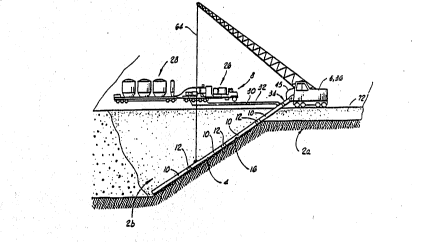
The apparatus shown in FIG. 14 is a preferred
embodiment for cutting soil and forming subsurface
containment barriers. The support 5 is a telescoping
boom excavator, such as the Gradall 880 excavator. A
pilot trench 72 is cut in Xnown manner. A source of
fluid i8 provided by lines 30 and 32 to the top of the
beam 4 which is also the conduit for the means for
creating a cutting action. ~he fluid lines 30 and 32 are
preferably connected to high pressure pump 34 and grout
plant 36 in order to provide a high pressure grout
slurry. The beam 4 is preferably a heavy wall steel pipe
which comes in 12 foot sections with linking assem~ly 6
shown in more detail in FIG. 15 which shows pivot point
21 which allows beam 4 to pivot relative to boom 9, with
jet port area 7 shown in more detail in FIG. 16 which
cont~in6 a plurality of jet ports across its width and a
cutter 22 which breaks up small obstructions contacted in
its reciprocating movement, and failing that will stop
the conduit and direct the force of the jet streams
against the obstruction until it is destroyed. Shield ~3
helps eliminate sharp edges and possible snags on
obstructions at this point on the beam 4. End jet port
area 8 is shown in more detail in FIG. 17 and contains
jet ports to cut at different angles from the axis of
b4am 4 in order to cut away obstacles that might
W093/0~3 PCTIUS92/05303
-29-
2a9~2L~2
interfere with the end of beam 4 and also containing
cutter 22 which serves the same function as the cutter
shown in FIG. 16. Beam 4 is attached to boom 9, which
comprises means for providing reciprocating action,
preferably by a hydraulic cylinder with an inner cylinder
structure 24 which moves in and out of outer cylinder
structure 25. Cylinder structure 24 preferably comprises
a cylinder and a rigidifying support structure.
Boom 9, attached to support 5, has the capability of
rotating back and forth around the axis of the length of
the boom which provides the capability to change the
direction of the cutting action from the reciprocating
jet streams in order to turn corners to shape the
containment barrier being formed, tG avoid obstacles,
etc.
With regard to all the embodiments, mechanical
cutters as shown for the embodiments of FIGS. 1-7, for
example, can be affixed to the subsurface members of the
present invention to aid in cutting a path through the
soil, which cutting is primarily performed hydraulically
in the illustrated embodiments. Additionally, it is also
to be noted that the density and gel strength development
c~aracteristics of the fluidized barrier material mixed
with the cut 60il should be adequate to support the
overburden weight of (e.g., this would begin at locus 106
in FIG. 8). This is continued while the conduit is
pulled transversely to its length so that the trench is
extended trnnsversely to its length. Referring to FIG.
8, by w~y of example, the frame by which the locus 106 is
defined sinks through sectors 108, 110 and partial
cylinder 112; the fr~me is then pulled through the
remainder of the volumes 114, 116, 118, 120. This is
controlled so t~at the tranRversely extended trench
extends not only alongside but also underneath the volume
W093~00483 PCT/US92/053~3
~090~ 30-
of soil or material within the ~onfines of the resultant
basin. Pullinq of the conduit occurs either or both
automatically in response to gravity due to the density
of the conduit or its support or mechanically in response
to movement of a suitable vehicle such as a crane or
other suitable tractor unit.
Thus, the present invention is well adapted to carry
out the objects and attain the ends and advantages
mentioned above as well as those inherent therein. While
preferred embodiments of the invention have been
described for the purpose of this disclosure, changes in
the construction and arrangement of parts and the
performance of steps can be made by those skilled in the
art, which changes are encompassed within the spirit of
this invention as defined by the appended claims.
The soil cutting according to this invention is
preferably accomplished by rapidly moving the fluid jet
stre~ms from the cutting means of the apparatus of this
invention across the face of the ~oil being cut 50 as to
force all the cutting action to occur within 80 jet
diameters of the jet orifice or port, and more preferably
within 30 jet diameters. Cutting efficiency drops off
exponentially with increasing distance between the soil
to be cut and the jet orifice or port. For example a
.078 inch diameter ~et nozzle operating with S000 psi
fluid should cut 4 times as many cubic incbes per second
at 4 inches ~s it does at 8 inches away from the target
60il. To keep the fluid jet streams from penetrating too
far into the soil with common soils it is preferable to
move them at linear velocities from 1 to 6 feet per
second, with 2 to 4 feet per second being more preferred.
The diameter of the fluid ports of this invention
may vary cver a wide range. However, with preferred
w~9~/00483 PCT/US92/05303
2~9D2~2
fluids port diameters between .078 inch and .156 inch are
preferred. Using standard 9oo horsepower pumping units,
jet ports of a smaller diameter are operable. However,
smaller diameter jet ports are also more prone to
plugging and must be moved at a faster speed. Since
there are a finite number of jet streams that can be
produced, the jet ports must be spaced more widely as the
depth or cutting face area increases. The length of the
stroke of the reciprocating mechanism which moves the jet
streams across the soil to be cut may be from about 4
feet to about 40 feet long with 8 feet to 16 feet being
the preferred stroke length to be compatible with
existing telescoping boom excavating equipment. Shorter
strokes require greater numbers of jet streams and
smaller diameter jet ports.
The high pressure fluid used to cut and modify the
~oil is preferably pumped at pressures from about 400 psi
to about lO,000 p8i, with 2000 psi to 5000 psi being more
preferred in common soil types.
The weiqht of the cutting means in a slurried soil
is preferably sufficient that at any given operating
angle the reaction thrust of the jet streams is less than
the forward thrust due to gravity.
The 80il cutting method and apparatus of this
invention can be practiced with any type of support or
carrier such a~ a crane, tracked backhoe, cherry picker,
tractor, truck, or a dozer. A preferred support i8 a
t~le~coping boom excavator such as the Gradall 880
excavator for moderate depths of about 70 feet. This
unit is preferred because it has a powerful reciprocating
mechanism. This eliminates the need to add this capacity
to the support. The Gradall excavator's ability to
rotate the conduit of the cutting means is also desirable
W093/0~3 PCT/US92/05303
-32-
20~V2~2
for turning corners in the soil with the apparatus of
this invention. A special hydraulic valve package may be
added to this unit to automate both the reciprocation and
the travel of the carrier.
The preferred apparatus consists of a network of
electric solenoid valves which, when activated, for
example by a pus~ button, cause the beam 4 of FIG. 14 to
automatically reciprocate at top speed. Moving any of
the standard joystick controls will shut off the
automatic mode and restore normal operation. When in the
auto stoke mode the movement of t~e excavator is
controlled by a sensor mounted on the end of the boom.
When the beam 4 of FIG. 14 falls to a specified angle
lS with respect to the boom 9 the tracks are automatically
activated to move the excavator several inches backward
(but in the direction that the soil cutting is
proceeding). This tends to keep the beam 4 and the boom
9 parallel or at a preset angle with respect to each
other. A gravity reference angle sensor mounted on the
non-reciprocating portion of the boom 9 allows the
operator to set the angle of the boom in order to
exercise a degree of control over t~e dept~ of operation.
The preferred soil cutting apparatus of this
invention can be operated with any type of pumpable
fluid. A fluid which will set up into an impermeable
barrier is preferred. Especially preferred are those
which will form long lasting barriers, such as Portland
cement based fluidfi. Such a fluid preferably contains
particles no larger than about 1/3 the diameter of the
~et port. ~e preferred fluid for forming impermeable
walls is a mixture of Portland cement, bentonite, or
flya~h wit~ water. The final wall material is pre~erably
formed from 1 part jetted slurry and rrom 1/2 to 2 parts
original soil The slurry composition is preferably
w093/0~3 PCT/US9~/05303
2030~'12
designed to give acceptable final properties within a
wide range of soil loadings. Other materials such as hot
wax or polymer grout can a~so be used. Polymer gelled
water may be used when it is de ired to form a temporary
slurry filled trench wherein a drainage pipe is laid and
the trench filled with permeable material for the purpose
of intercepting and recovering contaminated groundwater.
The cutting means of the apparatus of this invention
preferably comprises one or more conduits for high
pressure fluid, preferably weighing from about 50 to
about lSO pounds per linear foot with 80 to 120 pounds
per foot being most preferred for common soils where a 12
inch wide wall is to ~e formed. The cutting means may be
relatively flexible or relatively rigid, with greater
rigidity being preferred to make monitoring of operating
depth more accurate. The spatial orientation of the jet
streams may take many forms but the preferred form is to
have a transverse row of 5 to 7 jet streams covering a
width of 12 inches. These jet streams are preferably
perpendicular to the axis of the conduit of the cutting
means.
In a preferred embodiment this row of jet streams is
repeated every 12 feet of the length of the conduit. An
additional group of jet streams is preferably added on
the bottom end of the conduit of the cutting means which
i8 angled 45 degrees forward to aid in cutting into hard
rOrmations. The diameter of the jet ports cho~en for any
particulnr row may be varied according to the hardness of
the 80il at that level. The conduit may be fabricated in
one or more pieces but the preferred method is to
rabricate the conduit in modular 12 foot long sections
with the rows of jet streams mounted in replaceable
holders every 12 feet of conduit length.
W093/0~3 PC~/US92/~53~3
2~90~2 ~34-
At each row of jet streams it is preferred to have a
knife edged protrusion (cutter) which is intended to
catch on any solid obstructions which are encountered on
the downward stroke of the up and down movement of the
reciprocal movement of the cutting means. The cutter
serves to break up small obstructions or failing that it
will stop the conduit and direct the force of the jet
streams against the obstruction until it is destroyed.
The diameter of the conduit of the cutting means
preferably varies in size, being significantly smaller
generally compared to the diameter of the area where the
jet ports are located, in order that rocks and debris
which are loosened by the jet streams may readily pass
around the relatively small diameter conduit. This may
be accomplished by adding a truss to the arm of the
cutting means with large openings to allow for the
pas6age of rock6 and debris. Preferably for a saw which
cuts a 12 inch wide path and has a modular jet port area
which is 12 inches wide connected to a body of heavy wall
steel pipe. A preferred steel pipe contains a 6.5 inch
outside diameter and a 3 inch inside diameter.
The flow rates of the fluid through the conduit of
the apparatus of this invention preferably vary from
about 50 gallons per minute to about 1000 gallons per
minute, ~nd more preferably from about 200 to about 600
gallonfi per minute.
The cutting means of this invention may also include
a vibrating in place of the conduit for transmitting
fluids to form reciprocating fluid jet streams. The
vibrating beam cuts the sDil by the combination of
resonant vibrations, the shape and size of tbe beam and
tbe weight of the beam per unit length of the beam. A
hardening fluid is pumped down a smaller conduit attached
. .
W~93/00~3 PCT/~S92/05303
-35-
20902~2
to the beam. This fluid is mixed into the soil by the
vibration of the beam.
In addition to obtaining downward force by means of
gravity downward force may also be applied mechanically
or hydraulically, or by pulling a trailing cutting means
angled downward into the 60il forward through the soil by
means of a tractor or other carrier means. By locking
the angle of the cutting means to ground in place as the
cutting means is pulled forward additional downward force
is applied to the cutting means.
For very deep cuts into the soil, such as over 25
feet in depth, the use of gravity to increase the
downward force into the soil is increasingly important
since it becomes difficult if not impossible through
normal soils due to strength of materials and the limited
power of carriers to pull such cutting means through the
~oil at all, or to do so without bending or ot~erwise
distorting the cutting means out of shape.
Common soils for best results of the applications
and methods of this invention are sandy soil, loam, moist
clay, gravel and combination~ thereof. Baked clays,
hardened Texas gu~bo, solid rock or-the like are
generally not acceptable. However, the preferred fluid
cu~ting of this invention can cut through steel pipe and
very ~trong debris materials when the various cutting
par~ceters are optimized for cutting through such
materials according to the normal s~ills of this art.