Note: Descriptions are shown in the official language in which they were submitted.
- MATT.TNG MAc~TNF. INCLUDING SHORT
SHEET LENGTH DETECTING MEANS
BACKGROUND OF THE INVENTION
The present invention is generally concerned with
apparatus including sheet feeding and printing structures,
and more particularly with a mailing machine including a
base adapted to have mounted thereon a postage meter, and
improved drive systems and control structures therefor.
This application is related to the following two
concurrently filed Canadian Patent Applications by A.
Eckert, Jr. et. al. and assigned to the assignee of the
present invention: serial No. 2090235 for Mailing Machine
Including Sheet Feeding and Printing Speed Calibrating
Means and Serial No. 2090735 for Mailing Machine Including
Skewed Sheet Detection Means. In addition, this
application is related to the following two Canadian Patent
Applications by A. Eckert, Jr., et. al. and also assigned
to the assignee of the present invention: Serial No.
2084863, filed December 8, 1992 for Mailing Machine
Including Shutter Bar Control System; and Serial No.
2085261 filed December 14, 1992 for Mailing Machine
Including Printing Drum Control System.
-
209a~v~7
As shown in U.S. Patent No. 4,774,446, for a
Microprocessor Controlled D.C. Motor For controlling
Printing Means, issued September 27, 1988 to Salazar, et.
al. and assigned to the assignee of the present invention,
there is described a mailing machine which includes a base
and a postage meter removably mounted thereon. The base
includes sheet feeding structure for feeding a sheet in a
downstream path of travel through the machine, and includes
two sheet sensing structures located a known distance from
one another along the path of travel. And, the postage
meter includes a rotary printing drum for printing postage
indicia on a sheet while fee~inq the sheet downstream in the
path of travel therebeneath. The sensors successively sense
the sheet in the path of travel and provide successive
signals to a microprocessor to permit the time lapse between
the signals to be used for calculating a count col~e~onding
to the sheet feeding speed. Moreover, the base includes a
d.c. motor for driving the postage printing drum, and an
encoder coupled to the drum drive shaft for providing
signals indicative of the position thereof to a counting
circuit which, in turn, provides a count to the
microprocessor indicative of the peripheral speed of the
postage printing drum. And, the computer is programmed to
successively sample the counts corresponding to the sheet
feeding speed and the speed of the periphery of the drum to
adjust the motor drive between sampling time instants and
generate a motor drive signal for causing the motor to drive
the drum at a velocity which matches the peripheral speed of
the drum with the sheet f~e~;ng speed.
Thus it is know in the art to provide a closed loop,
sampled data, feed back control system in a mailing machine
base for continuously matching the peripheral speed of a
postage printing drum to the feeding speed of a sheet.
As shown in U.S. Patent No. 4,864,505 for a Postage
Meter Drive System, issued September 5, 1989 to Miller, et.
al. and assigned to the assignee of the present invention,
there is described a mailing machine base having a postage
2 1~ 91 ~?J S7
~ ,.
meter mounted thereon, wherein the base includes a first
d.c. motor for driving the postage printing drum via a drum
gear in the meter, a second d.c. motor for driving the
structure for feeding a sheet through the machine, and a
third, stepper, motor for driving a linkage system connected
in bearing engagement with the postage meter shutter bar for
moving the shutter bar out of and into locking engagement
with the drum drive gear.
Thus it is known in the art to provide three separate
motors for driving the sheet fee~ing, shutter bar moving and
postage printing drum driving structures in a mailing
machine base. And, it is known to provide a stepper motor
for driving a linkage system to move the postage meter
shutter bar into and out of locking engagement with the drum
i5 drive gear.
As shown in U.S. Patent No. 4,787,311, for a Mailing
Machine Envelope Transport System, issued November 29, 1988
to Hans C. Mol and assigned to the assignee of the present
invention. There is described a mailing machine base having
a postage meter mounted thereon, wherein the time lapse
between spaced sensors in the path of travel of a sheet is
utilized by a microprocessor for calculating a sheet feeding
speed, and wherein the speed of a stepper motor, connected
for driving the postage printing drum under the control of
the microprocessor, is adjusted to match the peripheral
speed of the drum with the sheet feeding speed.
Thus it is known in the art to provide a microprocessor
driven stepper motor in a mailing machine base for driving a
postage printing drum at a peripheral speed which matches
the speed of a sheet fed therebeneath.
As noted above, the structures utilized in the prior
art for sheet feeding, shutter bar moving and postage
printing drum driving purposes include the sophisticated
feedback control system of the '446 patent, which
continuously controls the motion of a postage printing drum
2 ~ 7
_ - 4 -
to conform the same to a trapezoidal-shaped velocity versus
time profile, having a constant velocity portion which
results in the peripheral speed of the drum matching the
speed of sheets fed through a mailing machine, and include
the relatively inexpensive alternative of the '311 patent,
which includes a stepper motor operated for matching the
peripheral speed of the drum to the sheet feeding speed
without regard to the acceleration and deceleration
velocity versus time profile characteristics of the drum.
Each of such systems has its drawbacks, for example,
encoders are expensive, as are software solutions which
take into consideration the technical specifications of the
motors controlled thereby. And both of such expenses are
major considerations in competitively pricing mailing
machines for the marketplace. Further, stepper motors are
noisy, as are linkage systems, which tend to suffer from
wear and tear over time and become noisy. Moreover, the
combination of a stepper motor and linkage system for
driving a shutter bar tends to cause the moving shutter bar
to be noisy. In addition to being irritable to customers,
noise normally signals wear and tear and, since mailing
machines must normally withstand the wear and tear of many
thousands of operational cycles in the course of their
expected useful life, maintenance problems are compounded
by the use of noisy systems in mailing machines. And, such
considerations are of major importance in generating and
retaining a high level of customer satisfaction with the
use of mailing machines. Accordingly:
an object of an aspect of the invention is to provide
an improved, low cost, low operational noise level, mailing
machine base;
another object of an aspect of the invention is to
provide improved microprocessor controlled sheet feeding,
shutter bar moving and postage printing drum driving
structures in a mailing machine base;
2 ~
- 4a -
another object of an aspect of the invention is to
provide a microprocessor controlled d.c. motor for
accelerating sheet feeding rollers at a substantially
constant rate to a substantially constant sheet feeding
speed;
another object of an aspect of the invention is to
provide a microprocessor controlled shutter bar moving
system in a mailing machine base;
another object of an aspect of the invention is to
provide a microprocessor controlled d.c. motor for timely
accelerating a postage meter drum from rest, in its home
position, to a substantially constant velocity, and then
maintaining the velocity constant;
another object of an aspect of the invention is to
provide a microprocessor controlled d.c. motor for timely
controlling deceleration of a postage printing drum from a
substantially constant velocity to rest in its home
posltlon;
another object of an aspect of the invention is to
provide a method and apparatus for calibrating the sheet
feeding speed of sheet feeding rollers to conform the speed
to a predetermined speed;
another object of an aspect of the invention is to
provide a method and apparatus for calibrating the printing
speed of a rotary printing drum to conform the printing
speed to the speed of a sheet fed thereto;
another object of an aspect of the invention is to
provide a method and apparatus for detecting skewed sheets
fed to a mailing machine base; and
another object of an aspect of the invention is to
~~ - 5 -
provide a method and apparatus for detecting sheets of
insufficient length fed to a mailing machine for printing
postage indicia thereon.
SUMMARY OF THE INVENTION
A mailing machine comprising, means for feeding a
sheet in a path of travel, a fence for defining a direction
of the
,.,~.
~0~2~7
path of travel and against which an edge of a sheet is
normally registered for alignment thereof in the path of
travel, means for printing postage indicia on a sheet in the
path of travel, the printing means including a rotary
postage indicia printing drum, the printing means including
means for driving the drum, means for controlling the sheet
feeding and drum driving means, the controlling means
including a microprocescor, the controlling means including
means for sensing a sheet in the path of travel and
providing a signal to the microproc~ssor when a sheet is fed
into and out of blocking relationship with the sensing
means, the signal having a first magnitude when a sheet is
not disposed in blocking relationship with the sensing
means, the signal having a second magnitude when a sheet is
disposed in blocking relationship with the sensing means,
the second signal magnitude having a time duration
corresponding to an overall length of a sheet as measured in
the direction of the path of travel, and the microprocessor
programmed for commencing a count when a sheet is fed into
blocking relationship with the sensing means of a
predetermined time interval corresponding to a minimum
overall sheet length acceptable for printing purposes
determining whether the sheet is still in blocking
relationship with the sensing means at the end of the count,
and implementing a shut-down routine if the sheet is not in
blocking relationship with the sensing means at the end of
the count.
BRIEF DESCRIPTION OF THE DRAWINGS
As shown in the drawings wherein like reference
numerals designate like or corresponding parts throughout
the several views:
Fig. 1 is a schematic elevation view of a mailing
machine according to the invention, including a base having
a postage meter mounted thereon, showing the sheet feeding
structure of the base and the postage printing drum of the
2~25q
meter, and showing a microprocessor for controlling the
motion of the sheet feeding structure and the drum;
Fig. 2 is a schematic end view of the mailing machine
of Fig. 1, showing the postage printing drum, drum drive
gear and shutter bar of the meter, and showing the shutter
bar and drum drive systems of the base;
Fig. 3 is a schematic view of structure for sensing the
angular position of the shutter bar cam shaft of Fig. 2, and
thus the location of the shutter bar relative to the drum
drive gear;
Fig. 4 is a schematic view of structure for sensing the
angular position of the printing drum idler shaft of Fig. 2,
and thus the location of the postage printing drum relative
to its home position;
Fig. 5 is a schematic view of the substantially
trapezoidal-shaped velocity versus time profile of desired
rotary motion of the postage printing drum of Fig. l;
Fig. 6 is a flow chart of the main line program of the
microprocessor of the mailing machine base of Fig. 1,
showing the supervisory process steps implemented in the
course of controlling sheet feeding, and shutter bar and
postage printing drum motion;
Fig. 7 is a flow chart of the sheet feeder routine of
the microprocessor of Fig. 1, showing the process steps
implemented for accelerating the sheet feeding rollers to a
constant feeding speed, and thereafter maintaining the speed
constant.
Fig. 8 is a flow chart of the shutter bar routine of
the microprocessor of Fig. 1, showing the process steps
implemented for controlling shutter bar movement out of and
into locking engagement with the postage printing drum drive
gear;
2~ ~ ~2~
.i, .
Fig. 9 is a flow chart of the postage meter drum
acceleration and constant velocity routine of the
microprocessor of Fig. 1, showing the process steps
implemented for controlling the rate of acceleration of the
postage printing drum, from rest in its home position to a
substantially constant sheet feeding and printing speed, and
thereafter controlling the drum to maintain the speed
constant;
Fig. 10 is a flow chart of the postage printing drum
deceleration and coasting routine of the microprocessor of
Fig. 1, showing the process steps implemented for
controlling the rate of deceleration of the postage printing
drum, from the substantially constant sheet feeding and
printing speed, to rest in its home position;
Fig. 11 is a flow chart of the power-up routine of the
microprocessor of Fig. 1, showing the process steps
implemented for selectively causing the sheet feeding speed
calibration routine(s) to be implemented;
Fig. 12 is a flow chart of the sheet feeder calibration
routine of the microprocessor of Fig. 1, showing the process
steps implemented for causing the sheet feeding speed of the
sheet feeding rollers to be conformed to a predetermined
sheet feeding speed;
Fig. 13 is a flow chart of the rotary printing drum
calibration routine of the microprocessor of Fig. 1, showing
the process steps implemented for causing the printing speed
of the postage printing drum to be conformed to a
predetermined sheet feeding speed;
Fig. 14 is a partial, schematic, top plan, view of the
mailing machine of Fig. 1, showing successive positions of a
sheet relative to the registration fence as the sheet is fed
to the sheet sensing structure:
. 2~Q~S7
Fig. 15 is a diagram showing a typical voltage versus
time profile of the magnitude of the voltage of the signal
provided to the microprocessor of Fig. 1 by the sheet
sensing structure of Fig. 14 as the sheet is fed into
blocking relationship with the sensing structure;
Fig. 16 is a partial, schematic, top plan, view of the
mailing machine of Fig. 1, showing successive positions of a
sheet which is typically skewed relative to the registration
fence as the sheet is fed to the sheet sensing structure;
Fig. 17 is a diagram showing a typical voltage versus
time profile of the signal provided to the microprocessor of
Fig. 1 by the sheet sensing structure of Fig. 16 as the
typically skewed sheet is fed into blocking relationship
with the sensing structure;
Fig. 18 is a flow chart of the sheet skew detection
routine of the microprocessor of Fig. 1, showing the process
steps implemented for detecting successive unskewed, and
typically skewed, sheets fed to the mailing machine base;
Fig. 19 is a partial, schematic, top plan view of the
mailing machine of Fig. 1, showing successive positions of a
sheet which is of insufficient length, are measured in the
direction of the path of travel thereof, for example due to
being atypically skewed relative to the registration fence,
as the sheet is fed to the sheet sensing structure; and
Fig. 20 is a diagram showing a typical voltage versus
time profile of the signal provided to the microprocessor of
Fig. 1 by the sheet sensing structure of Fig. 19 as a sheet
of a predetermined minimum length, as measured in the
direction of the path of travel, is fed to the sheet sensing
structure.
DESCRIPTION OF THE PREFERRED EMBODIMENTS
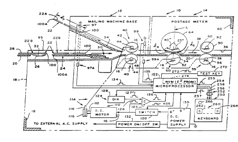
As shown in FIG. 1, the apparatus in which the
invention may be incorporated comprises a mailing machine 10
-- 10 --
2 Q 9 Q 2 ~j rg~
.,,.=
including a base 12 and a postage meter 14 which is
removably mounted on the base 12.
The base 12 (Fig. 1) generally includes suitable
framework 16 for supporting the various component thereof
including a housing 18, and a horizontally-extending deck 20
for supporting sheets 22 such as cut tapes 22A, letters,
envelopes 22B, cards or other sheet-like materials, which
are to be fed through the machine 10. Preferably, the base
12 also includes conventional structure 24 for selectively
deflecting an envelope flap 26 from an envelope body 28
together with suitable structure 30 for moistening the strip
of glue 32 adhered to the envelope flap 26, preparatory to
feeding the envelope 22B through the machine 10. In
addition, the base 12 preferably includes an elongate
angularly-exten~ing deck 34 for receiving and guiding cut
tapes 22A past the moistening structure 30 preparatory to
being fed through the machine 10. When mounted on the base
12, the postage meter 14 forms therewith a 36 slot through
which the respective cut tapes 22A, envelopes 22B and other
sheets 22 are fed in a downstream path of travel 38 through
the machine 10.
For feeding sheets 22 into the machine 10, the base 12
preferably includes input feeding structure 40 including
opposed, upper and lower, drive rollers, 42 and 44, which
are axially spaced parallel to one another and
conventionally rotatably connected to the framework 16, as
by means of shafts, 46 and 48, so as to extend into and
across the path of travel 38, downstream from the cut tape
receiving deck 34. In addition, the base 12 includes
conventional intermediate feeding structure 50, including a
postage meter input roller 52, known in the art as an
impression roller, which is suitably rotatably connected to
the framework 16, as by means of a shaft 54 so as to extend
into and across the path of travel 38, downstream from the
lower input drive roller 44. Still further, for feeding
sheets 22 from the machine 10, the base 12 includes
conventional output feeding structure 55, including an
11 - 2 0 ~ 7
_
output feed roller 56 which is suitably rotatably connected
to the framework 16, as by means of a shaft 58, so as to
extend into and across the path of travel 38, downstream
from the impression roller 52.
As shown in Fig. 2, the postage meter 14 comprises
framework 60 for supporting the various components thereof
including rotary printing structure 62. The rotary printing
structure 62 includes a conventional postage printing drum
64 and a drive gear 66 therefor, which are suitably spaced
apart from one another and mounted on a common drum drive
shaft 68 which is located above and axially extends parallel
to the impression roller drive shaft 54, when the postage
meter 14 is mounted on the base 12. The printing drum 64 is
conventionally constructed and arranged for feeding the
respective sheets 22 (Fig. 1) in the path of travel 38
beneath the drum 64, and for printing postage data,
registration data or other selected indicia on the upwardly
disposed surface of each sheet 22. When the postage meter 14
is mounted on the base 12, the printing drum 64 is located
in a home position thereof which is defined by an imaginary
vertical line L ext~n~ing through the axis thereof, and the
impression roller 52 is located for urging each sheet 22
into printing engagement with the printing drum 64 and for
cooperating therewith for feeding sheets 22 through the
machine 10. The drum drive gear 66 (Fig. 2) has a key slot
70 formed therein, which is located vertically beneath the
drum drive shaft 68 and is centered along an imaginary
vertical line L1 which extends parallel to the home position
line L of the printing drum 64. Thus, when the key slot 70
is centered beneath the axis of the drum drive shaft 68 the
postage meter drum 64 and drive gear 66 are located in their
respective home positions. The postage meter 14
additionally includes a shutter bar 72, having an elongate
key portion 74 which is transversely dimensioned to fit into
the drive gear's key slot 70. The shutter bar 72, which is
conventionally slidably connected to the framework 60 within
the meter 14, is reciprocally movable toward and away from
the drum drive gear 66, for moving the shutter bar's key
- 12 - 2~02~7
. .,
portion 74 into and out of the key slot 70, under the
control of the mailing machines base 12, when the drum drive
gear 66 is located in its home position. To that end, the
shutter bar 72 has a channel 76 formed therein from its
lower surface 78, and, the base 12 includes a movable lever
arm 80, having an arcuately-shaped upper end 82, which
extends upwardly through an aperture 84 formed in the
housing 18. When the meter 14 is mounted on the base 10,
the lever arm's upper end 82 'fits into the channel 76, in
bearing engagement with the shutter bar 72, for reciprocally
moving the bar 72. As thus constructed and arranged, the
shutter bar 72 is movable to and between one position,
wherein shutter bar's key portion 74 is located in the drum
drive gear' key slot 70, for preventing rotation of the drum
drive gear 66, and thus the drum 64, out of their respective
home positions, and another position, wherein the shutter
bar's key portion 74 is located out of the key slot 70, for
permitting rotation of the drum drive gear 66, and thus the
drum 64.
The postage meter 14 (Fig. 1) additionally includes an
output idler roller 90 which is suitably rotatably connected
to the framework 60, as by means of an idler shaft 92 which
axially extends above and parallel to the output roller
drive shaft 58, for locating the roller 90 above and in
cooperative relationship with respect to the output feed
roller 56, when the postage meter 14 is mounted on the base
12. Further, the base 12 additionally includes conventional
sheet aligning structure including a registration fence 95
defining a direction of the path of travel 38, i.e.,
extending parallel to the fence 95, and against which an
edge 96 (Fig. 2) of a given sheet 22 is normally urged when
fed to the mailing machine 10 for aligning the given sheet
22 with the direction of the path of travel 38. Moreover,
the base 12 (Fig. 1) preferably includes sheet detection
structure 97, including a suitable sensor 97A, located
upstream from the input feed rollers, 42 and 44, for
detecting the presence of a sheet 22 being fed to the
machine 10. And, the base 12 preferably includes sheet
- 13 - 2~
feeding trip structure 99, including a suitable sensor 99A,
located downstream from the input feed rollers, 42 and 44,
and preferably substantially one-half of an inch from, and
thus closely alongside of, the registration fence 94, for
sensing the leading edge 100 and trailing edge lOOA of each
sheet 22 fed thereby into the mailing machine 10.
As shown in Fig. 1, for driving the input, intermediate
and output sheet feeding structures 40, 50 and 55, the
mailing machine base 12 preferably includes a conventional
d.c. motor 110 having an output shaft 112, and a suitable
timing belt and pulley drive train system 114
interconnecting the drive roller shafts 48, 54 and 58 to the
motor shaft 112. In this connection, the drive train system
114 includes, for example, a timing pulley 116 fixedly
secured to the motor output shaft 112 for rotation therewith
and a suitable timing belt 118 which is looped about the
pulley 116 and another timing pulley of the system 114 for
transmitting motive power from the pulley 116, via the
remainder of the belt and pulley system 114, to the drive
roller shafts 48, 54 and 58.
As shown in Fig. 1, for controlling the angular
velocity of the sheet feeding rollers 44, 52 and 56, and
thus the speed at which sheets 22 are fed into, through and
from the machine 10, the mailing machine base 12 preferably
includes a field effect transistor (FET) power switch 120
which is conventionally electrically connected to the d.c.
motor 110 for energization and deenergization thereof. In
addition, for controlling the sheet feeding speed, the base
12 includes the sheet detection structure 97 and sheet
feeding trip structure 99, a microprocessor 122 to which the
FET power switch 120, sheet detection structure 97 and sheet
feeding structure 99 are conventionally electrically
connected, and a voltage comparing circuit 124 which is
conventionally electrically interconnected between the
microprocessor 122 and d.c. motor 110. Preferably, the
voltage comparing circuit 124 includes a conventional solid
state comparator 125, having the output terminal thereof
- 14 ~ 2~2 j;7
' ,_
connected to the microprocessor 122. In addition, the
comparator 125 has one of the input terminals thereof
connected to the d.c. motor 110, for sampling the motor's
back-e.m.f. voltage and providing a signal, such as the
signal 126, to the comparator 125 which corresponds to the
magnitude of the back-e.m.f. voltage. And, the comparator
}25 has the other of the input terminals thereof connected
to the microprocessor 122 via a suitable digital to analog
converter 128, for providing the comparator 125 with a
signal, such as the signal 127, which corresponds to a
predetermined reference voltage. Further, the base 12
includes a conventional d.c. power supply 130, to which the
FET power switch 120 and microprocessor 122 are suitably
connected for receiving d.c. power. Moreover, the base 12
includes a manually operable on and off power switch 132,
which is electrically connected to the d.c. supply 130 and
is conventionally adapted to be connected to an external
source of supply of a.c. power for energizing and
deenergizing the d.c. supply 130 in response to manual
operation of the power switch 132. In addition, for
controlling the sheet feeding speed, the microprocessor 122
is preferably programmed, as hereinafter discussed in
greater detail, to respond to receiving a sheet detection
signal, such as the signal 134, from the sensor 97A, to
receiving a sheet feeding signal, such as the signal 135
from the sensor 99A, and to receiving successive positive or
negative comparison signals, such as the signal 136 from the
comparator 125, for causing the d.c. motor 110 to drive each
of the sheet feeding rollers 44, 52 and 56 at the same
peripheral speed for feeding sheets 22 through the machine
10 at a constant speed.
As shown in Fig. 2, for driving the shutter bar lever
arm 80, the mailing machine base 12 preferably includes a
conventional d.c. motor 140, having an output shaft 142, and
includes a drive system 144 interconnecting the lever arm 80
to the motor shaft 142. The drive system 144 preferably
includes a timing pulley 146 which is suitably fixedly
connected to the output shaft 142 for rotation therewith.
209~
, ._
In addition, the drive system 144 includes a cam shaft 148,
which is conventionally journaled to the framework 16 for
rotation in place, and includes a rotary cam 150, which is
conventionally connected to the cam shaft 148 for rotation
therewith. Moreover, the drive system 144 includes a timing
pulley 152, which is suitably fixedly connected to the cam
shaft 148 for rotation thereof. Preferably, the rotary cam
150 and pulley 152 are integrally formed as a single
piecepart which is injection molded from a suitable plastic
material. In addition, the drive system 144 includes a
conventional timing belt 154, which is suitably looped about
the pulleys, 146 and 152, for transmitting rotary motion of
the motor drive shaft 142 to the cam shaft 148, and thus to
the rotary cam 150. Still further, the drive system 144
includes the lever arm 80, which is preferably
conventionally pivotally attached to the framework 16, as by
means of a pin 156, and includes a yoke portion 158
depending therefrom. Preferably, the rotary cam 150 is
disposed in bearing engagement with the yoke portion 158 for
pivoting the yoke portion 158, and thus the lever arm 80,
both clockwise and counterclockwise about the pin 156.
For controlling movement of the shutter bar lever arm
80 (Fig. 2), and thus movement of the shutter bar 72, into
and out of the drum drive gear slot 70, the mailing machine
12 includes the microprocessor 122, and includes the sheet
feeding trip structure 99 (Fig. 1) which is conventionally
electrically connected to the microprocessor 122. In
addition, for controlling shutter bar movement, the machine
10 (Fig. 2) includes a power switching module 160 which is
connected between the d.c. motor 140 and microprocessor 122.
Preferably, the switching module 160 includes four FET power
switches arranged in an H-bridge circuit configuration for
driving the d.c. motor 140 in either direction. In
addition, the switching module 160 preferably includes
conventional logic circuitry for interconnecting the FET
bridge circuit to the d.c. motor 140 via two electrical
leads, rather than four, and for interconnecting the FET
bridge circuit to the microprocessor 140 via two electrical
- 16 - 2Q~s G~2~7
leads, 161A and 161B, rather than four, such that one of the
leads, 161A or 161B, may be energized, and the other of the
leads, 161B or 161A, deenergized, as the case may be, for
driving the d.c. motor 140 in either direction. In
addition, for controlling movement of the shutter bar 72,
the base 12 includes cam shaft sensing structure 162
electrically connected the microprocessor 122. The
structure 162 includes a cam-shaped disk 164, which is
conventionally fixedly mounted on the cam shaft 148 for
rotation therewith. The disk 164 (Fig. 3) includes an
elongate arcuately-shaped lobe 166, having an
arcuately-extending dimension dl which corresponds to a
distance which is slightly less than, and thus substantially
equal to, a predetermined linear distance d2 (Fig. 2)
through which the shutter bar key portion 74 is preferably
moved for moving the shutter bar 72 out of locking
engagement with the drum drive gear 66. Preferably
however, rather than provide the disk 164, the rotary cam
150 is provided with a lobe portion 166A which is integrally
formed therewith when the cam 150 and pulley 152 are
injection molded as a single piecepart. And, the shaft
position sensing structure 162 includes conventional lobe
sensing structure 168 having a sensor 170 (Fig. 3) located
in the path of travel of lobe, 166 or 166A as the case may
be. As thus constructed and arranged, when the cam shaft
148 (Fig. 2) is rotated counter-clockwise, the lever arm 80
is pivoted thereby about the pin 156 to move the shutter bar
72 through the distance d2 and out of locking engagement
with the drum drive gear 66. Concurrently, the lobe, 166 or
166A (Fig. 3), is rotated counter-clockwise through the
distance d2, causing the leading edge 172 thereof, followed
by the trailing edge 174 thereof, to be successively
detected by the sensor 170, for providing first and second
successive transition signals, such as the signal 175 (Fig.
2), to the microprocessor 122, initially indicating that
movement of the shutter bar 72 has commenced and that the
shutter bar 72 lobe 166 or 166A (Fig. 3) is blocking the
sensor 170, followed by indicating that movement of the
shutter bar 72 (Fig. 2) has been completed and that the
- 17 - 2~ 5
sensor 170 (Fig. 3) is unblocked. Thereafter, when the cam
shaft 148 (Fig. 2) is rotated clockwise, the lever arm 80 is
pivoted thereby about the pin 156 to move the shutter bar 72
back through the distance d2 and into locking engagement
with the drum drive gear 66. And, concurrently, the lobe,
166 or 166A (Fig. 3), is rotated clockwise, through the
distance d2 causing the trailing edge 174 thereof, followed
by the leading edge 172 thereof, to be successively detected
by the sensor 170, for providing third and fourth successive
transition signals 175 to the microprocessor 122 which again
successively indicate that movement of the shutter bar 72
has commenced and that the sensor 170 (Fig. 3) is blocked,
and movement of the shutter bar 72 (Fig. 2) has been
completed and the sensor 170 (Fig. 3) is unblocked. In
addition, for controlling movement of the shutter bar 72
(Fig. 2), the microprocessor 122 is preferably programmed,
as hereinafter described in greater detail, to respond to
receiving a sheet feeding signal 135 from the sensor 99A,
and to receiving successive sets of transition signals 175
(Fig. 2) from the sensing structure 168, for timely causing
the FET module 160 to drive the d.c. motor 140 to rotate the
cam 150 counter-clockwise, for moving the shutter bar 72
through the distance d2 and thus out of locking engagement
with the drum drive gear 66 and until the second of the
successive transition signals 175 is received, and, after a
predetermined time interval during which the printing drum
64 is driven through a single revolution as hereinafter
discussed, for causing the FET module 160 to then drive the
d.c. motor 140 to rotate the cam 150 clockwise, for moving
the shutter bar 72 back through the distance d2 until the
fourth of the successive transitions signals 175 is received
to indicate that the shutter bar 72 has been moved into
locking engagement with the drum drive gear 66.
As shown in Fig. 2, for driving the drum drive gear 66
and thus the drum 64, the mailing machine base 12 preferably
includes a conventional d.c. motor 180, having an output
shaft 182, and includes a drive system 184 for
interconnecting the drum drive gear 66 to the motor shaft
- 18 -
2 C ~ ~ 2 ~ 7
-
182 when the postage meter 14 is mounted on the mailing
machine base 12. The drive system 184 preferably includes a
timing pulley 186 which is suitably fixedly connected to the
motor output shaft 182 for rotation therewith. In addition,
the drive system 184 includes an idler shaft 188, which is
conventionally journaled to the framework 16 for rotation in
place, and includes a timing pulley 190, which is
conventionally fixedly connected to the idler shaft 188 for
rotation thereof. Moreover, the drive system 184 includes a
conventional timing belt 192, which is suitably looped about
the pulleys, 190 and 186, for transmitting rotary motion of
the motor drive shaft 182 to the idler shaft 188, and thus
to the pulley 190. Preferably, the base 12 additionally
includes a pinion gear 194, which is conventionally mounted
on, or integrally formed with, the idler shaft 188 for
rotation therewith. Further, the base 12 also includes an
idler shaft 196, which is conventionally journaled to the
framework 16 for rotation in place, and includes a drive
system output gear 198. Preferably, the output gear 198 is
suitably dimensioned relative to the drum drive gear 66 such
that the gear ratio therebetween is one-to-one. And, the
drive system ouL~ gear 198 is conventionally fixedly
mounted on the idler shaft 196 for rotation thereof and is
dimensioned so as to extend upwardly through an aperture 199
formed in the housing 18 to permit the drum drive gear 66 to
be disposed in meshing engagement with the drive system
output gear 198, when the postage meter 14 is mounted on the
base 12, for driving thereby to rotate the printing drum 64
into and out of engagement with respective sheets 22 fed
into the machine 10.
For controlling rotation of the drive system output
gear 198 (Fig. 2), and thus rotation of the printing drum
64, the mailing machine base 12 includes the microprocessor
122, and includes power switching structure 200 connected
between the d.c. motor 180 and the microprocessor 122.
Preferably, the switching structure 200 includes a first FET
power switch 202, nominally called a run switch, which is
energizeable for driving the motor 180 in one direction,
- 19 - 2~û2-~3~
i.e., clockwi~e, and includes a second FET power switch 204,
nominally called a brake switch, connected in shunt with the
first FET power switch 202, which is energizeable for
dynamically braking the motor 180. In addition, for
controlling rotation of the printing drum 64, the base 12
includes a voltage comparing circuit 206, which is
conventionally electrically interconnected between the
microprocessor 122 and d.c. motor 180. Preferably, the
voltage comparing circuit 206 includes a solid state
comparator 208, having the output terminal thereof connected
to the microprocessor 122. ln addition, the comparator 208
has one of the input terminals thereof connected to the d.c.
motor 180, for sampling the motor's back-e.m.f. voltage and
providing a signal, such as the signal 210 to the comparator
208 which corresponds to the magnitude of the back-e.m.f.
voltage. And, the comparator 208 has the other of the input
terminals thereof connected to the microprocessor 122, via a
suitable digital to analog converter 212 for providing the
comparator 208 with an analog signal, such as the signal
214, which corresponds to a predetermined reference voltage.
In addition, for controlling rotation of the printing drum
64, the base 12 includes idler shaft position sensing
structure 220 electrically connected to the microprocessor
122. The structure 220 preferably includes a cam-shaped
disk 222, which is conventionally fixedly mounted on the
idler shaft 196 for rotation therewith and thus in step with
counter-clockwise rotation of the drum 64, due to the
one-to-one gear ratio between the drive system output gear
198 and drum drive gear 66. The disk 222 (Fig. 4) includes
two, elongate, arcuately-shaped lobes, 224 and 226. The
lobes 224 and 226 are preferably separated from one another
by a two degree gap 228 which is bisected by a vertical line
L2 which extends through the axis of the disk 222 when the
disk 222 is located in its home position, which home
position corresponds to the home position of the drum drive
gear slot 70 (Fig. 2) and thus to the home position of the
printing drum 64. The lobe 224 (Fig. 4) has an
arcuately-extending dimension d3, which corresponds to a
distance which is preferably slightly less than, and thus
- 20 - 2~90~
"",
substantially equal to, the linear distance d4 (Fig. 1)
through which the outer periphery of the printing drum 64 is
initially driven counter-clockwise from the home position
thereof before being rotated into engagement with a sheet 22
fed into the machine 10. And, the lobe 226 (Fig. 4) has an
arcuately-extending dimension d5 which corresponds to a
distance which is preferably slightly less than, and thus
substantially equal to, the linear distance d6 (Fig. 1)
through which the outer periphery of the printing drum 64 is
driven counter-clockwise upon being rotated out of
engagement with a ~heet 22 fed thereby through the machine
10. Further, the shaft position sensing structure 220
includes conventional lobe sensing structure 230 having a
sensor 232 (Fig. 4) located in the path of travel of the
lobes, 224 and 226. As thus constructed and arranged,
assuming the shutter bar 72 (Fig. 2) is moved out of locking
engagement with the drum drive gear 66, when the drive
system output gear 198 commences driving the drum drive gear
66 and printing drum 64 from their respective home
positions, the disk 222 (Fig. 4) is concurrently rotated
counter-clockwise from its home position. As the lobe 224
is rotated through the distance d3, causing the leading edge
234 of the lobe 224, followed by the trailing edge 236
thereof, to be successively detected by the sensor 232,
successive first and second transition signals, such as the
signal 240 (Fig. 2), are provided to the microprocessor 122,
initially indicating that drum 64 (Fig. 2) has commenced
rotation from the home position thereof, followed by
indicating that the drum 64 has rotated 40~ through the
distance d4. In addition, the transition signal 240
provided by the sensor 232 detecting the lobe's trailing
edge 236 indicates that the drum 64 has rotated into f~e~; ng
engagement with a sheet 22 fed into the machine 10.
Thereafter, when the disk 222 and thus the drum 64 (Fig. 1)
continue to rotate counter-clockwise, and the printing drum
64 prints indicia on the sheet 22 as the sheet 22 is fed
thereby through the machine 10, until such rotation causes
the leading edge 242 (Fig. 4) of the lobe 226, followed by
the trailing edge 244 thereof, to be successively detected
- 21 - 2 ~ 9 0 2 ~ 7
1~
by the sensor 232. Whereupon the sensor 232 provides
successive third and fourth transition signals 240 to the
microprocesFor 122, initially indicating that the drum 24
has rotated 335~ and out of feeding engagement with the
sheet 22, followed by indicating that the drum 64 has
rotated through 359~, and thus substantially through the
distance d6 and back to the home position thereof. Still
further, for controlling rotation of the printing drum 64,
the microprocessor 122 is preferably programmed, as
hereinafter described in greater detail, to timely respond
to the completion of movement of the shutter bar 72 out of
locking engagement with drum drive gear 66, to timely
respond to the transition signals 240 from the idler shaft
sensing structure 230 and to timely respond to receiving
successive positive or negative comparison signals, such as
the signal 248 from the comparator 208, to cause the FET
switch 202 to drive the d.c. motor 180 for initially
accelerating the drum 64 through an angle of 40~, followed
by driving the drum 64 at a constant velocity through an
angle of 295~, to drive each of the rollers 44, 52 and 56 at
the same peripheral, sheet feeding, speed. Moreover, the
microprocessor 122 is preferably programmed to timely
deenergize the FET run switch 202, and to energize the FET
brake switch 204 to thereafter decelerate and dynamically
brake rotation of the motor 180 to return the drum 64
through an angle of 25~ to the home position thereof at the
end of a single revolution of the drum 64.
In addition, for controlling operation of the base 12
(Fig. 1) and thus the machine 10, the base 12 preferably
includes a conventional keyboard 250 which is suitably
electrically connected to the microprocessor 122 by means of
a serial communications link 252, including a data input
lead 254, for providing signals, such as the signal 255, to
the microprocessor 122, a data output lead 256, for
providing signals, such as the signals 257 to the keyboard
250, and a clock lead 258 for providing clock signals to the
keyboard 250 to synchronize communication between the
keyboard 250 and microprocessor 122. The keyboard 250,
- 22 - 2 ~ J ~7
, .......................................................... .
which has a plurality of manually actuatable switching keys
260, preferably includes a print mode key 262, which is
manually actuatable for causing the base 12 to enter into a
sheet feeding and printing mode of operation, and a no-print
mode key 264, which is manually actuatable for causing the
base 12 to enter into a sheet feeding but no printing mode
of operation. Further, for providing a visual indication to
an operator concerning a trouble condition in the machine
10, the keyboard 260 preferably includes a service lamp 266
which is preferably intermittently energized in a light
blinking mode of operation in response to signals 257 from
the microprocessor 122 whenever the base 12 is in need of
servicing, for example, due to the occurrence of a jam
condition event in the course of operation thereof.
Moreover, for controlling operation of the base 12, the base
12 preferably includes a manually actuatable test key 270,
which is preferably disposed within the housing 18 of the
base 12 for access and use by manufacturing and maintenance
personnel. The test key 270 is conventionally electrically
connected to the microprocessor 122 and is manually
actuatable to provide a signal, such as the signal 272, to
the microprocessor 122 for causing the base 12 to enter into
one or more calibration modes of operation, wherein the
sheet feeding and printing speeds of the base 12 and postage
meter 14 are calibrated to ensure that the postage indicia
printed on a given sheet 22 is acceptably located thereon.
Further, for storing critical data utilized for operation of
the base 12 in various modes thereof, including the
calibration mode(s), the base 12 preferably includes a
suitable non-volatile memory (NVM) 274 which is
conventionally electrically connected to the microprocessor
122 and operable thereby for storing therein data without
loss thereof due to power failure or during power-down
conditions. And, to that end, the microprocessor 122 is
preferably one of the type which includes an electrically
erasible, ~oyrammable~ read only, memory (EEPROM).
As shown in Fig. 6, in accordance with the invention
the microprocessor 122 is preferably programmed to include a
- 23 - 2~Q257
~ ,_
main line program 300, which commences with the step 302 of
conventionally initializing the microprocessor 122 (Figs. 1
and 2) in response to the operator manually moving the power
switch 132 to the "on" position thereof to energize the d.c.
power supply 120 and thus the mailing machine base 12. Step
302 generally includes establishing the initial voltage
levels at the microproc~ssor interface ports which are
utilized for sending and receiving the signals 275, 272,
134, 176, 175, 240, 136 and 248 to and from the keyboard,
test key, sensors and comparators 250, 270, 97A, 99A, 170,
232, 125 and 248, (Fig. 1, 2, 3 and 4) for controlling the
various structures of the mailing machine base 12, and
setting the interval timers and event counters of the
microprocessor 122. Thereafter, the microprocessor 122
executes the step 304 (Fig. 6) of initializing the
components of the aforesaid various structures. Step 304
generally entails causing the microprocessor 122 (Figs. 1, 3
and 4) to scan the microprocessor ports connected to the
various sensors, 97A, 99A, 170 and 232, and, if neceCcAry~
to cause the main line program to enter into a print mode of
operation and drive the motors 110, 140 and 180 for causing
various components of the base 12 and meter 14, including
the drum drive gear 66, and thus the printing drum 64, to be
dri~en to their respective home positions from which
operation thereof, and thus of the mailing machine 10 may be
initiated.
Assuming completion of the initialization steps 302 and
304 (Fig. 6), then, according to the invention, the program
300 enters into an idle loop routine 306 which commences
with the step 308 of determining whether or not a a machine
error flag has been set, due to the occurrence of various
events, hereinafter discussed in greater detail, including,
for example, the sheet feeding structures 40, 50 or 55 (Fig.
1) being jammed in the course of feeding a sheet 22 through
the machine 10, the shutter bar 72 (Fig. 2) not being fully
moved through the distance d2 in the course of movement
thereof either out of or into locking engagement with the
drive gear 66, or the meter drive system 184 being jammed in
- 24 - 2 ~ 9 ~ 25 7
".",,.~
the course of driving the same. Assuming a machine error
flag has been set, step 308 tFig. 6), the program 300
returns processing to idle 306, until the condition causing
the error flag to be set is cured and the error flag is
cleared, and a determination is thereafter made that an
error flag has not been set, step 308. Whereupon, the
microprocessor 122 causes the program 300 to implement the
step 310 of determining whether or not the sheet feeding or
printing speed calibration flag has been set, due to the
test key 270 (Fig. 1) having been actuated as hereinafter
discussed. Assuming the calibration flag has not been set,
step 310 (Fig. 6), the program 300 implements the step 312
of determining whether or not a sheet detection signal 134
(Fig. 1) has been received from the sensor 97A of the sheet
detection structure 97, and, assuming that it has not been
received, step 312 (Fig. 6), the program 300 loops to idle,
step 306, and continuously sllscessively implements steps
308, 310, 312, and 306 until the sheet detection signal 134
is received. Whereupon, the program 300 implements the step
314 of setting the sheet feeder routine flag "on", which
results in the routine 300 calling up and implementing the
sheet feeder routine 400 (Fig. 7), hereinafter discussed in
detail.
As the routine 400 (Fig. 7) is being implemented, the
program 300 (Fig. 6) concurrently implements the step 316 of
determining whether or not the sheet detection signal 134
has ended, followed by the step 316A of setting the skew
detection routine flag "on", which results in calling up and
implementing the sheet skew detection routine 1000 (Fig. 6)
hereinafter described in detail. As the skew detection
routine 1000 is being implemented, the program 300 (Fig. 6)
concurrently implements the step 317 of determining whether
a skew flag has been set, as hereinafter discussed in
detail, indicating that the sheet 22 (Fig. 1) being fed into
the machine 10 is askew relative to the direction of the
path of travel 38 defined by the registration fence 95.
Assuming, however as is the normal case that the skew flag
is not set, step 317, then, the program 300 (Fig. 6)
- 25 - 2~257
~i
implements the step 318 of determining whether the sheet
feeding trip signal flag has been set, indicating that a
sheet fee~ing trip signal 135 (Fig. 1) has been received
from the sensor 99A of the sheet feeding trip structure 99.
Assuming that it is determined that the sheet detection
signal 134 has not ended, step 316 (Fig. 6) and, in
addition, it is determined that the sheet feeding trip
signal flag has not been set, step 318 indicating that the
microprocessor 122 has not received the sheet feeding trip
signal, then, the program 400 returns processing to step 316
and continuously successively implements steps 316, 317 and
318 until the sheet feeding trip signal 135 is received,
step 318, before the sheet detection signal 134 is ended,
step 316. If, in the course of such processing, the sheet
detection signal ends, step 316, before the sheet feeding
trip signal is received, step 318, then, the program 300
implements the step 319, of setting the sheet feeder routine
flag "off" followed by returning processing to step 312.
Thus the program 300 makes a determination as to whether or
not both sensors 97A and 99A (Fig. 1) are concurrently
blocked by a sheet 22 fed to the machine 10 and, if they are
not, causes sheet feeding to be ended. As a result, if an
operator has fed a sheet 22 to the mailing machine base 12
and it is sensed by the sensor 97A, but is withdrawn before
it is sensed by the sensor 99A, although the sheet feeding
routine 400 (Fig. 7) has been called up and started, step
314 (Fig. 6), it will be turned off, step 319, until
successive implementations of step 312 result in a
determination that another sheet detection signal, step 312,
has been received and the program 300 again implements the
step 314 of setting the sheet feeder routine flag "onn.
Assuming however, that both the sheet detection and fee~in~
signals, 134 and 135, are received, steps 316 and 318,
before the sheet detection signal 134 is ended, step 316,
then, the program 300 implements the step 320 of determining
whether the base 12 is in the no-print mode of operation, as
a result of the operator having actuated the no-print key
264 (Fig. 1). Assuming that the no-print key 264 has been
actuated, step 320 (Fig. 6), due to the operator having
- 26 - 2 ~ Q~ 2 5 7
' ,,.,_
chosen to use the base 12 (Fig. 1) for sheet feeding
purposes and not for the purpose of operating the postage
meter 14, then, the program 300 (Fig. 6) by-passes the drum
driving steps thereof and implements the step 320A of
causing program processing to be delayed for a time interval
sufficient to permit the sheet 12 being fed by the base 12
to exit the machine 10. Assuming however, that the base 12
is not in the no-print mode of operation, step 320, then the
program 300 implements the step 320B of determining whether
the base 12 (Fig. 1) is in the print mode of operation, as a
result of the operator having actuated the print key 262.
Assuming, the inquiry of step 320B (Fig. 6) is negative, due
to the operator not having chosen to use the base 12 for
both sheet feeding and postage printing purposes, then, the
program 300 returns processing to step 320 and continuously
successively implements steps 320 and 320B until the
operator actuates either the print or no-print key, 262 or
264 (Fig. 1) to cause the inquiry of one or the other of
steps 320 or 320B (Fig. 6) to be affirmatively determined.
Assuming that the print key 262 is actuated, causing the
inquiry of step 320B to be affirmative, then the program 300
implements the step 321 of starting a time interval counter
for counting a predetermined time interval td (Fig. 5), of
substantially 80 milliseconds, from the time instant that a
sheet 22 (Fig. 1) is detected by the sensing structure 99 to
the predetermined time instant that the printing drum 64
preferably commences acceleration from its home position in
order to rotate into engagement with the leading edge 100 of
the sheet 22 as the sheet 22 is fed therebeneath.
Thereafter, the program 300 (Fig. 6) implements the
step 322 of setting the shutter bar routine flag "on", which
results in the program 300 calling up and implementing the
shutter bar routine 500 (Fig. 8), hereinafter discussed in
detail, for driving the shutter bar 72 (Fig. 2) through the
distance d2 and thus out of locking engagement with the drum
drive gear 66. As the routine 500 (Fig. 8) is being
implemented, the program 300 (Fig. 6) concurrently
implements the step 324 of determining whether or not the
- 27 - 2
shutter bar 72 (Fig. 2) has stopped in the course of being
driven through the distance d2 and thus out of locking
engagement with the drum drive gear 66. Assuming that the
shutter bar 72 is ctopped, then, the program 300 (Fig. 6)
implements the step 326 of causing the shutter bar 72 (Fig.
2) to be driven back into locking engagement with the drum
drive gear 66, step 326 (Fig. 6~, followed by returning
processing to idle, step 306. If however, the shutter bar
72 (Fig. 2) is not stopped in the course of being driven
through the distance d2, and thus out of locking engagement
with the drum drive gear 66, then, the program 300 (Fig. 6)
implements the step 328 of determining whether or not the
time interval count, started in step 321, has ended. And,
assuming that it has not, the program 300 continuously loops
through step 328 until the time interval td is ended.
Thereafter, before the program 300 implements the step 330
of setting the postage meter routine flag "on", which
results in the ~lo~Lam 300 calling up and implementing the
postage meter acceleration and constant velocity, or postage
printing, routine 600 (Fig. 9). The program 300 preferably
implements the step 329 (hereinafter discussed in greater
detail) of determining whether the sheet feeding trip signal
flag found to be set in step 318 is still set, to determine
whether the sheet 22 disposed in blocking relationship with
the sensor 99A is still disposed in blocking relationship
therewith after the time delay interval td of 80
milliseconds, and thus to determine whether the sheet 22 is
of sufficient length for printing purposes. Assuming, at
this juncture, as is the normal case that the inquiry of
step 329 is affirmative, indicating that the sheet 22 is of
sufficient length, then, the program 300 implements the step
330 of setting the postage meter acceleration and constant
velocity routine flag "on", which results in the program 300
calling up and implementing the postage meter acceleration
and constant velocity, or postage printing, routine 600
(Fig. 9).
As the routine 600 (Fig. 9) is being implemented, the
program 300 (Fig. 6) concurrently implements the step 332 of
- 28 -
2~2~
clearing a time interval counter for counting a first
predetermined fault time interval, of preferably 100
milliseconds, during which the microprocessor 122 (Fig. 2)
preferably receives the initial transition signal 240 from
the sensing structure 220, due to the printing lobe's
leading edge 234 (Fig. 4) being sensed by the sensor 232,
indicating that the postage printing drum 64 (Fig. 2) has
commenced being driven from its home position by the drum
drive gear 66. Accordingly, after clearing the time
interval counter, step 332 (Fig. 6), the program 300
implements the step 334 of determining whether or not the
printing drum 64 has commenced movement from its home
position. And, assuming that it has not, the program 300
continuously successively implements the successive steps of
determining whether or not the first fault time interval has
ended, step 336, followed by determining whether or not the
drum 64 has moved from its home position, step 334, until
either the drum 64 has commenced moving before the first
fault time interval ends, or the first fault time interval
ends before the drum has commenced moving. Assuming the
first fault time interval ends before the drum has moved,
then, the program 300 implements the step 338 of setting a
machine error flag and causing the keyboard service lamp
266 to commence blinking, followed by the step 340 of
2S causing a conventional shut-down routine to be implemented.
Accordingly, if the postage printing drum 64 is not timely
driven from its home position at the end of the time delay
interval td (Fig. 5) of substantially 80 milliseconds, and
after commencement of implementation of the postage meter
acceleration and constant velocity routine, step 330 (Fig.
6), the program 300 causes processing to be shut down, and a
blinking light 266 (Fig. 1) to be energized to provide a
visual indication to the operator that the mailing machine
base 12 or postage meter 14, or both, are in need of
servicing. At this juncture, the operator of the machine 10
may find, for example, that the drum 64 did not move from
its home position due to the postage meter 14 having
insufficient funds to print the postage value entered
therein by the operator for printing purposes, or some other
- 29 - 2~ 9 ~ 25 7
error condition has occurred in the meter 14 which preludes
driving the drum 64 from its home position. Alternatively,
the operator may find that a jam condition exists in the
base 12 which prevents the drum drive gear 66 from driving
the drum 64. Whatever may be the reason for the drum 64 not
being timely moved from its home position during the time
interval, the operator would normally cure the defect, or
call an appropriate service person to do so, before the
machine 10 is returned to normal operation. Accordingly, as
shown in Fig. 6, after implementation of the shut-down
routine, step 340, the program 300 implements the step 342
of making a determination as to whether or not either of the
print or no-print mode keys, 260 or 262, (Fig. 1) is
actuated. And, assuming that a mode key, 260 or 262, has
not been actuated, which determination would normally
indicate that the trouble condition which resulted in
implementation of the shut down routine, step 340 (Fig. 6)
had not as yet been cured, then the program 300 causes
processing to continuously loop through step 342 until one
of mode keys, 260 or 262, is actuated. Whereupon the
program 300 implements the step 344 of causing the error
flag to be cleared, followed by returning processing to
idle, step 306.
Referring back to step 334 (Fig. 6), and assuming as is
the normal case that the postage printing drum 64 is timely
moved from its home position, i.e., before the first
predetermined fault time interval is ended, step 336 (Fig.
6), then, the program 300 causes the time interval counter
to be cleared, step 346, and to commence counting a second
predetermined fault time interval, of preferably 100
milliseconds, during which the microprocessor 122 (Fig. 2)
preferably receives the next transition signal 240 from the
sensing structure 220, due to the printing lobe's trailing
edge 236 (Fig. 4) being sensed by the sensor 232, indicating
that the postage printing drum 64 ( Fig. 2) has rotated
through the initial 40~ of rotation thereof from its home
position (Fig. 5). Accordingly, after clearing the time
interval counter, step 346 (Fig. 6), the program 300
~ 30 - 2~ 9 ~ ~ S 7
''11'_
implements the step 348 of determining whether or not the
40~ transition signal 240 has been received. And, assuming
that it has not, the program 300 continuously successively
implements the successive steps of determining whether or
not the second fault time interval has ended, step 350,
followed by determining whether or not the 40~ transition
signal 240 has been received, step 348, until either the 40~
transition signal 240 is received before the second fault
time interval ends, or the second fault time interval ends
before the 40~ transition signal 240 is received. Assuming
that the second fault time interval ends before the 40~
transition signal 240 is received, then, the program 300
implements the step 352, corresponding to step 338, of
setting a machine error flag and causing the keyboard
service lamp 266 to commence blinking, followed by
implementing the successive machine shut-down and start-up
steps 340, 342 and 344, hereinbefore discussed in detail,
and returning processing to idle, step 306.
On the other hand, assuming as is the normal case that
a determination is made in step 348 (Fig. 6) that the 40~
transition signal was timely received, i.e., at the end of
the time interval t1 (Fig. 5) of preferably 40 milliseconds,
and thus before the second predetermined fault time interval
is ended, step 350 (Fig. 6), then, the program 300 causes
the time interval counter to be cleared and to commence
counting a third predetermined fault time interval, of
preferably 500 milliseconds, during which the microprocessor
122 (Fig. 2) preferably receives the next transition signal
240 from the sensing structure 220, due to the printing
lobe's leading edge 242 (Fig. 4) being sensed by sensor 232,
indicating that the postage printing drum 64 (Fig. 2) has
rotated through 335~ of rotation thereof from its home
position. Thereafter, the program 300 implements the
successive steps of clearing a second time interval counter,
step 356, for counting the duration of actual constant speed
of rotation of the postage printing drum 64, followed by the
step 358 of making a determination as to whether or not the
335~ transition signal 240 has been received, step 350.
2~ 32~7
1~1~
Assuming that the 335~ transition signal 240 is not
received, the program 300 continuously successively
implements the successive steps of determining whether or
not the third fault time interval has ended, step 360,
followed by determining whether or not the 335~ transition
signal 240 has been received, step 358, until either the
335~ transition signal 240 is received before the third
fault time interval ends, or the third fault time interval
ends before the 335~ transition signal 240 is received.
Assuming the third fault time interval ends before the 335~
transition signal 240 is received, then, the program 300
implements the step 362, corresponding to step 338, of
setting a machine error flag and causing the keyboard
service lamp 266 to commence blinking, followed by
implementing the sllcc~scive machines shut-down and start-up
steps 340, 342 and 344, as hereinbefore discussed in detail,
and returning processing to idle, step 306. However,
assuming as is the normal case that a determination is made
in step 358 that the 335~ transition signal 240 was timely
received, i.e., at the end of the time interval t2 (Fig. 5)
of preferably 292 milliseconds, and thus before the third
predetermined fault time interval is ended, step 360, then,
the program 300 implements the step 363 of storing the
actual time interval of duration of constant speed rotation
of the postage printing drum 64, followed by the step 364 of
setting the postage meter deceleration and coasting routine
flag "on", which results in the program 300 calling up and
implementing the postage meter deceleration and coasting
routine 700 (Fig. 10).
As the routine 700 (Fig. 10) is being implemented, the
program 300 (Fig. 6) concurrently implements the step 366 of
clearing the time interval counter for counting a fourth
predetermined fault time interval, of preferably 100
milliseconds, during which the microprocessor 122 (Fig. 2)
preferably receives the last transition signal 240 from the
sensing structure 220, due to the printing lobe's trailing
edge 244 (Fig. 4) being sensed by the sensor 232, indicating
that the postage printing drum 64 (Fig. 2) has rotated
- 32 -
2~9~2~7
through 359~ of rotation thereof from its home position and
is thus one degree from returning thereto. Thereafter, the
program 300 implements the step 368 of making a
determination as to whether or not the 359~ transition
signal 240 has been received. Assuming that it has not, the
program 300 continuously successively implements the
successive steps of determining whether or not the fourth
fault time interval has ended, step 370, followed by
determining whether or not the 359~ transition signal 240
has been received, step 368, until either the 359~
transition signal 240 is received before the fourth fault
time interval ends, or the fourth fault time interval ends
before the 359~ transition signal 240 is received. Assuming
the fourth fault time interval ends before the 359~
transition signal 240 is received, then, the program 300
implements the step 372, corresponding to step 338, of
setting a machine error flag and causing the keyboard
service lamp 266 to commence blinking, followed by
implementing the successive machine shut-down and start-up
steps 340, 342 and 344, as hereinbefore discussed in detail,
and returning processing to idle, step 306. However,
assuming as is the normal case that a determination is made
in step 368 that the 359~ transition signal 240 was timely
received, i.e., substantially at the end of the time
interval t3 of preferably 40 milliseconds, and thus before
the fourth predetermined fault time interval is ended, step
370, then, the program 300 implements the step 374 of
determining whether or not the postage meter cycle ended
flag has been set, i.e., whether or not the postage meter
deceleration and coasting routine 700 (Fig. 10) has been
fully implemented. Assuming that the postage meter cycle
ended flag has not been set, step 374, then, the program 300
(Fig. 6) continuously implements step 374 until the postage
meter cycle ended flag has been set. Whereupon, the program
300 implements the step 378 of setting a postage meter trip
cycle complete flag.
Thereafter, the program 300 (Fig. 6) implements the
step 380 of setting the shutter bar routine flag "on",
- 33 -
209G2~7
.,,. ~
which results in the program 300 calling up and implementing
the shutter bar routine 500 (Fig. 8), as hereinafter
discussed in detail, for driving the shutter bar 72 (Fig. 2)
back through the distance d2 and into locking engagement
with the drum drive gear 66. As the routine 500 is being
implemented, the program 300 concurrently implements the
step 382 of determining whether or not the shutter bar 12
(Fig. 2) has stopped in the course of being driven through
the distance d2 and thus into locking engagement with the
drum drive gear 66. Assuming the shutter bar 72 is stopped,
then, the program 300 (Fig. 6) implements the step 384 of
setting the machine error flag and causing the keyboard
service lamp 266 to commence blinking, followed by
implementing the sl~scessive machine shut-down and start-up
steps 340, 342 and 344, hereinbefore discussed in detail,
and returning processing idle, step 306. If however, as is
the normal case, a determination is made that the shutter
bar 72 has not stopped, then, the program 300 implements the
step 386 of deenergizing the FET brake ~witch 204 (Fig. 2),
to remove the shunt from across the postage meter drive
system's d.c. motor 180. Thereafter, the program 300
implements the step 320A of causing processing to be delayed
for a predetermined time interval, of preferably 500
milliseconds, to permit the sheet 22 being processed by the
machine 10 to exit the base 12, followed by the successive
steps 390 and 392, hereinafter discussed in detail, of
initially determining whether the stored, actual time
intervals of acceleration and deceleration of the postage
printing drum 64 (Fig. 2), and the actual movement time
interval of the shutter bar 72 in either direction, is not
equal to the design criteria therefor, followed by
incrementally changing the actual time intervals, as needed,
to cause the same to respectively be equal to their design
criteria value. Thereafter, the program 300 returns
processing to idle, ~tep 306.
As shown in Fig. 7, according to the invention, the
sheet fee~;ng routine 400 commences with the step 401 of
determining whether or not the sheet feeder routine flag
2~Q~2 ;7
~.
setting is "off" due to an error event occurring, such as
one of the sheet feeder jam conditions hereinbefore
discussed, in the course of operation of the mailing machine
base 12. Assuming that the sheet feeder routine flag
setting is "off", step 401, the routine 400 continuously
loops through step 401 until the sheet feeder routine "off"
flag has been cleared, i.e., reset to "on", for example, due
to the jam condition having been cured. However, assuming
that the sheet feeder routine flag setting is "on" then, the
routine 400 implements the step 402 of clearing a time
interval timer and setting the same for counting a first
predetermined time interval, of preferably 30 milliseconds,
during which the d.c. motor 110 (Fig. 1) is preferably
energized for slowly accelerating the sheet feeding rollers,
44, 50 and 55, at a ~ubstantially constant rate during the
predetermined time interval to a sheet feeding speed of
twenty six inches per second for feeding one sheet 22 each
480 milliseconds. Thus the routine 400 (Fig. 7) causes the
microprocessor 122 to implement the step 404 of energizing
and deenergizing the FET power switch 120 (Fig. 1) with a
fixed, pulse-width-modulated, signal, such as the signal
405, which preferably includes 10 positive duty cycle
energization pulses of one millisecond each in duration,
separated by 10 deenergization time intervals of two
milliseconds each in duration, so as to provide one
energization pulse during each successive three millisecond
time interval for 10 successive time intervals, or a total
of 30 milliseconds. The energization pulses are
successively amplified by the FET switch 120 (Fig. 1) and
applied thereby to the d.c. motor 110 for driving the
rollers 44, 52 and 56, via the belt and pulley system 114.
Thereafter, the routine 400 (Fig. 7) implements the step 408
of determining whether or not the acceleration time interval
has ended. Assuming the acceleration interval has not ended,
step 408, the routine 400 loops to step 404 and successively
implements steps 404 and 408 until the acceleration time
interval is ended, step 408. In this connection it is noted
that the preferred acceleration time interval of 30
milliseconds is not critical to timely accelerating the
2 ~ o ~
sheet f~e~ing rollers 44, 52 and 56 (Fig. 1) to the desired
sheet fee~ing speed of 26 inches per second, since the time
interval required for a given sheet 22 to be detected by the
sensor 97A to the time instant it is fed to the nip of the
upper and lower input feed rollers, 42 and 44, is much
greater than 30 milliseconds. Assuming the time interval
has ended, step 408, the routine 400 then implements the
step 410 of initializing an event counter for counting a
maximum predetermined number of times the counter will be
10 permitted to be incremented, as hereinafter discussed,
before it is concluded that a jam condition exists in the
sheet feeding structure. Thereafter, the routine 400 causes
the microprocessor 122 to implement the step 412 of
determining whether or not the sheet feeder routine flag
15 setting is "off", due to an error event occurring, such as
one of the jam conditions hereinbefore discussed, in the
course of operation of the mailing machine base 12.
Assuming that the sheet feeder routine flag setting is
"off", step 412, the routine 400 returns processing the step
20 401. Whereupon, the routine 400 continuously loops through
step 401, as hereinbefore discussed, until the flag is reset
to "on". Assuming, however that the sheet feeder routine
flag setting is "on", for example due to the jam condition
having been cleared, then, the routine 400 implements the
25 step 414 of delaying routine processing for a predetermined
time interval, such as two milliseconds, to allow for any
transient back e.m.f. voltage discontinuities occurring
incident to deenergization of the d.c. motor 110 to be
damped. Thereafter, the routine 400 causes the
30 microprocessor 122 (Fig. 1) to sample the output signal 136
from the comparator 125 to determine whether or not the d.c.
motor back e.m.f. voltage signal 126 is greater than the
reference voltage signal 127, step 416 (Fig. 7).
Assume as in normal case that the back e.m.f. voltage
35 is greater the reference voltage, step 416 (Fig. 7), due to
the rollers 44, 52 and 56 having been accelerated to a sheet
feeding speed which is slightly greater than the desired
sheet feeding speed of 26 inches per second, because the
- 36 - 2~J~'l7
rollers 44, 52 and 56 are not then under a load. At this
juncture the sheet feeding speed is substantially equal to
the desired sheet feeding speed, and, in order to maintain
the desired sheet feeding speed, the routine 400 implements
the successive steps of delaying processing one-half a
millisecond, followed by the step 420 of clearing the jam
counter, i.e., resetting the count to zero, and again
implementing the step 416 of determining whether or not the
motor back e.m.f. voltage is greater than the reference
voltage. Assuming that the inquiry of step 416 remains
affirmative, the routine 400 repeatedly implements steps
418, 420 and 416 until the back e.m.f. voltage is not
greater than the reference voltage, at which juncture it may
be concluded that the sheet feeding speed of the rollers 42,
52 and 56 is no longer substantially at the desired sheet
feeding speed. Accordingly, the routine 400 then implements
the step 424 of incrementing the jam counter by a single
count, followed by the step 426 of determining whether or
not the number of times the jam counter has been incremented
is equal to a predetermined maximum count of, for example,
100 counts. And, assuming that the maximum count has not
been reached, step 426, the microprocessor 122 causes the
FET power switch 120 to be energized, step 428, for applying
a d.c. voltage, such as the power supply voltage 134, to the
motor 110, followed by delaying processing for a fixed time
interval, step 430, of preferably two milliseconds, and then
deenergizing the FET switch 431, step 431, whereby the FET
power switch 120 is energized for a predetermined time
interval of preferably two milliseconds. Thereafter,
processing is returned to step 414. Accordingly, each time
the routine 400 successively implements steps 414, 416, 424,
426, 428, 430 and 431, the FET switch 120 and thus the d.c.
motor 110, is energized for a fixed time interval, steps
428, 430 and 431, and the jam counter is incremented, step
424, unless there is a determination made in step 416 that
the d.c. motor back e.m.f. voltage is greater than the
reference voltage, i.e., that the d.c. motor 110 is being
driven substantially at the constant sheet feeding speed.
~ 37 ~ 20~2~
Referring back to step 416 (Fig. 7), and assuming that
the comparison initially indicates that the back e.m.f. is
not greater than the reference voltage, indicating that the
sheet feeding rollers 44, 52 and 56 were not accelerated
substantially to the ~esired sheet feeding speed of 26
inches per second in th2 co~rse of implementation of steps
402, 404, and 408, then, the routine 400 continuously
successively imple~ents step 424, 426, 428, 430, 431, 412,
414 and 416 until, as hereinbefore discussed the back e.m.f.
voltage exceeds the reference voltage, step 416, before the
jam count maximizes, step 426, or the jam count maximizes,
step 426, before the back e.m.f. voltage exceeds the
reference voltage.
Since each of such jam counts, step 426 (Fig. 7), is
due to a determination having been made that the d.c. motor
back e.m.f. voltage is not greater than the reference
voltage, step 416, it may be concluded that there is no d.c.
motor back e.m.f. voltage when the jam count reaches the
maximum count, step 426. That is, it may be concluded that
the d.c. motor 110 is stalled due to a sheet feeding jam
condition occurring in the mailing machine 10. Accordingly,
if the jam count has reached the maximum count, the routine
400 implements the sllccesQive steps of setting the sheet
feeder flag "off", step 432, causing the keyboard service
lamp 266 to commence blinking, step 434, and then setting a
machine error flag for the main line program 300 (Fig. 6).
Thereafter, the routine (Fig. 7) 400 returns processing to
step 401. Whereupon, assuming that the motor jam condition
is not cleared, the routine 400 will continuously loop
through step 401 until the jam condition is cured and the
"off" flag setting is cleared.
As shown in Fig. 8, according to the invention, the
shutter bar routine 500 commences with the step 502 of
determining whether or not the shutter bar routine flag
setting is "off", due to an error event occurring, such as
the shutter bar 72 (Fig. 2) having been stopped in the
course of being driven out of or into locking engagement
- 38 -
2 ~ o
with the drive gear 66 in the course of prior operation
thereof. Assuming that the shutter bar routine flag setting
is "off", the routine 500 continuously loops through step
502 until the shutter bar routine flag "off" setting has
been cleared, i.e., reset to "on", for example due to jam
condition thereof having been cured. Assuming as is the
normal case that the shutter bar routine flag setting is
"on" then, the routine 500 implements the step 503 of
clearing a counter for counting the number of positive duty
cycle energization pulses the microprocessor 122 (Fig. 2)
thereafter applies to the FET power switching module 160 for
driving the d.c. motor 140. Thereafter the routine 500
implements the successive steps 504 and 506 of energizing
the appropriate lead, 161A or 161B, of FET power switch
module 160 (Fig. 2), depen~ing upon the desired direction of
rotation of the d.c. motor 140, with a first, fixed,
pulse-width-modulated, signal, such as the signal 505, which
preferably includes a single positive duty cycle
energization pulse of from 500 to 800 microseconds in
duration, step 504, followed by a single deenergization time
interval of from 500 to 200 microseconds in duration, step
506, so as to provide one energization pulse during a one
millisecond time interval. The signal 505, which is
amplified by the FET switching module 160 and applied
thereby to the d.c. motor 140, thus drives the motor 140 in
the appropriate direction of rotation corresponding to the
selected lead 161A or 161B, to cause the cam 150 to pivot
the shutter bar lever arm 80 in the proper direction about
the pivot pin 156 for causing the arm 80 to slidably move
the shutter bar 70 partially through the distance d2 for
movement thereof either out of or into locking engagement
with the drum drive gear 66. Thereafter, the routine 500
(Fig. 8) implements the step 507 of incrementing the pulse
counter, cleared in step 503, a single count, followed by
the step 508 of determining whether or not the shutter bar
sensor 170 tFig. 3) is blocked due to the shutter bar lobe's
leading edge 172, or 174, being sensed thereby, indicating
that the movement of the shutter bar 72 (Fig. 2) either out
of or into locking engagement with the drum drive gear 66
- 39 -
2 a t~ J ~; J
has commenced. Assuming the shutter bar sensor 170 (Fig. 3)
is not blocked, then, the routine 500 (Fig. 8) implements
the step 510 of determining whether or not a count of the
number of energization pulses applied to the FET switch 140,
step 504, has reached a first maximum count of preferably 15
pulses. Assuming the pulse count is less than the maximum
count, then, the routine 500 causes processing to be
returned to step 504 and to continuously successively
implement cteps 504, 506, 507, 508 and 510, until either the
shutter bar sensor 170 is blocked, step 508, before the
pulse count maximizes, step 510, or the pulse count
maximizes, step 510, before the shutter bar sensor 170 is
blocked, step 508. Assuming the shutter bar sensor 170 is
blocked, step 508, before the pulse count maximizes, step
510, then, the routine 500 implements the step 512 of
setting a shutter bar sensor blocked flag and returning
processing to step 510. Whereupon the routine 500
continuously successively implements steps 510, 504, 506,
507, 508, and 512 until the pulse count maximizes, step 510,
followed by implementing the successive steps 514 and 516 of
again energizing the appropriate lead, 161A or 161B, of FET
switching module 160, depending on the desired direction of
rotation of the d.c. motor 140, with a second, fixed,
pulse-width-modulated, signal 505, which preferably includes
a single positive duty cycle energization pulse of from 250
to 400 microseconds in duration, step 514, and thus a duty
cycle which is a predetermined percentage of, i.e.,
preferably 50% of, the duty cycle of the first
pulse-width-modulated signal 505, followed by a single
deenergization time interval of from 750 to 600 microseconds
in duration, step 516, so as to provide one energization
pulse during a one millisecond time interval. On the other
hand, with reference to step 508, assuming the shutter bar
sensor 170 is not blocked, before the pulse count maximizes,
step 510, then, the routine 500 directly implements the
successive steps 514 and 516 without having set the shutter
bar sensor blocked flag in step 512. Accordingly, whether
or not the shutter bar sensor blocked flag is set, step 512,
the routine 500 implements the successive steps 514 and 516
- 40 -
2~2~
._
of energizing the FET switching module 160 with the second
pulse-width-modulated signal 505 hereinbefore discussed.
Accordingly, during the initial 15 millisecond time interval
of energization of the FET switch, the sensor 170 may or may
not have been blocked by the shutter bar 72, that is, the
shutter bar 72 may or may not have commenced movement in
either direction. And, in either eventuality the FET
switching module 160 is again energized to either initially
move or continue to move the shutter bar 72. Thereafter,
the routine 500 implements the step 517 of incrementing the
pulse counter, cleared in step 503, a single count, followed
by the 518 determining whether or not the shutter bar sensor
170 is then or was previously blocked. Assuming the shutter
bar sensor 170 is not blocked, then, the routine 500
implements the step 520 of determining whether or not the
sensor 170 is unblocked and, in addition, whether or not the
sensor blocked flag is also set. Thus, the inquiry of step
520 is concerned with the occurrence of two events, that is,
that the shutter bar sensor 170 (Fig. 3) becomes blocked
and, thereafter, becomes unblocked by the lobe, 166 or 166A.
Assuming that the shutter bar sensor 170 is not unblocked,
whether or not the blocked sensor flag is set, or that the
sensor 170 is unblocked but the blocked sensor flag is not
set, then the routine 500 implements the step 522 of
determining whether or not the total count of the number of
energization pulses applied to the FET switch 140, step 514,
has reached a total maximum fault count of preferably 75
pulses. Assuming the total pulse count has not maximized,
then, the routine 500 causes processing to be returned to
step 514 and to continuously successively implement steps
514, 516, 517, 518, 520 and 522 until the shutter bar sensor
is blocked and thereafter unblocked, step 520. Assuming as
is the normal case that the shutter bar sensor is blocked,
step 518, before the total pulse count has maximized, step
522, then, the routine 500 implements the step 523 of
setting the sensor blocked flag before implementing step
520. If however, the shutter bar sensor is not thereafter
additionally unblocked, step 520, before the total pulse
count has maximized, step 522, the routine 500 concludes
- 41 - 2~ G~
that either a fault in the postage meter 14 or a jam
condition in the base 12 is preventing shutter bar movement.
Accordingly, the routine 500 implements the step 524 of
setting a shutter bar time out flag, followed by the step
S 526 of setting the shutter bar routine flag "off" and
returning processing to step 502. Whereupon, processing
will continuously loop through step 502 until the postage
meter fault or ~am condition is cured and the shutter bar
routine flag is set "on". At this juncture it will be
assumed, as is the normal case, that before the total pulse
count has maximized, step 522, the shutter bar sensor 170 is
timely unblocked after having been blocked, step 520, i.e.
typically at the end of a desired predetermined time
interval of preferably 30 milliseconds and thus typically
when the pulse count is equal to 30. Thus the routine 500
answers the inquiry of step 520, and implements the step 527
of storing the pulse count which, due to each count
occurring during successive time intervals of one
millisecond, corresponds to the actual time interval
required to drive the shutter bar 72 (Fig. 2) through
substantially the distance d2, without seating the same, and
thus substantially either out of or into locking engagement
with drum drive gear 66. Thereafter, in order to slow down
movement of the shutter bar 72 (Fig. 2), before the
positively seating the same, the routine 500 preferably
implements the step 528 (Fig. 8) of causing the
microprocessor 122 (Fig. 2) to apply a two millisecond
reverse energization pulse, to the FET switch lead 161A or
161B, as the case may be, which is opposite to the lead 161A
or 161B to which the energization pulses of steps 504 and
514, were applied. Thereafter, the routine 500 implements
the step 530 of delaying routine processing for a fixed time
interval, of preferably twenty milliseconds, followed by the
step 531 of clearing the pulse counter. Whereupon, in order
to positively seat the shutter bar while at the same time
easing the shutter bar 72 to a stop to reduce the audible
noise level thereof, the routine 500 implements the
successive steps 532 and 534 of energizing the FET switching
module 160 with a third fixed pulse width-modulated signal,
- 42 -
~, G~ J~'7
of preferably a single positive duty cycle energization
pulse of 500 microseconds in duration, followed by a single
deenergization time interval of 10 milliseconds in duration,
step 534. Thereafter, the routine 500 implements the step
535 of incrementing the pulse counter cleared in step 531 by
a single count, followed by the step 536 of determining
whether or not the number of energization pulses applied in
step 532 is equal to a predetermined maximum count, of
preferably four pulses. Assuming that the pulse count has
not maximized, then, the routine 500 returns processing to
step 532 and continuously successively implements steps 532,
534 and 536 until the pulse count maximizes step 536.
Whereupon the routine implements the step 526 of setting the
shutter bar routine flag "off" and returning processing to
step 502, which, as hereinbefore discussed, is continuously
implemented by the routine 500 until the shutter bar routine
flag setting is "onn.
As shown in Fig. 9, according to the invention, the
postage meter acceleration and constant velocity routine 600
commences with the step 602 of determining whether or not
the postage meter acceleration and constant velocity routine
flag setting is "off", as is the normal case, until, in the
course of execution of the main line program 300 (Fig. 6),
the program 300 implements the step 330 of setting the
acceleration and constant velocity routine flag "on".
Assuming that the acceleration routine flag setting is
"off", step 602 (Fig. 9), then, the routine 600 continuously
implements step 602 until the "off" flag setting is cleared.
Whereupon, the routine 600 implements the step 603 of
clearing and starting a time interval timer for measuring
the actual time interval required to accelerate the postage
printing drum 64 (Fig. 1) from its home position and into
printing and feeding engagement with a sheet 22 fed
therebeneath. Thereafter, the routine 600 (Fig. 9)
implements the successive steps 604 and 606 of energizing
the FET run switch 202 (Fig. 2) with a fixed,
pulse-width-modulated, signal, such as the signal 605, which
preferably includes a single positive duty cycle
_43_ ~ 02~7
energization pulse of 1.5 milliseconds in duration, step
604, followed by a single deenergization time interval of 2
milliseconds in duration, step 606, so as to provide one
energization pulse having a positive polarity duty cycle
during a 3.5 millisecond time interval. Thereafter, the
routine 600 implements the step 608 of causing the
microprocessor 122 (Fig. 2) to sample the output signal 248
from the comparator 208 to determine whether or not the d.c.
motor back e.m.f. voltage signal 210 is greater than the
reference voltage signal 214. If the comparator signal 248
indicates that the back e.m.f. voltage is not greater than
the reference voltage, step 608 (Fig. 9), it may be
concluded that the postage printing drum 24 has not yet
completed acceleration to the predetermined constant
velocity (Fig. 5), since the reference voltage corresponds
to the predetermined constant velocity that the drum 24
(Fig. 1) is preferably driven for feeding and printing
postage indicia on sheets 22 at a speed corresponding to the
sheet fee~ing speed of the sheet feeding rollers 44, 52 and
56. Thus if the inquiry of step 608 (Fig. 9) is negative,
the routine 600 returns processing to step 604, followed by
continuously successively implementing steps 604, 606 and
608 until the d.c. motor back e.m.f. voltage is greater than
the reference voltage. Whereupon it may be concluded that
the postage printing drum 64 is being driven substantially
at the predetermined constant velocity causing the periphery
thereof to be driven at the desired sheet feeding and
printing speed. Accordingly, the routine 600 then
implements the sl)Cc~csive steps of stopping the acceleration
time interval timer, step 609, followed by the step 609A of
storing the actual time interval required for acceleration
of the drum 64 (Fig. 1) to the constant velocity (Fig. 5).
Thereafter, in order to drive the drum 64 to maintain the
velocity constant, the routine 600 (Fig. 9) preferably
implements the successive steps 610 and 612 of energizing
the FET run switch 202 with a second, predetermined,
pulse-width-modulated signal, which preferably includes a
single positive duty cycle energization pulse of 4
milliseconds in duration, step 610, followed by a single
~ 44 ~ 20 9 0 ~ ~ 7
deenergization time interval of 2 milliseconds in duration,
step 612, so as to provide one energization pulse having a
positive polarity duty cycle during a six millisecond time
interval. Whereupon, the routine 600 implements the step
614, corresponding to step 608, of determining whether or
not the d.c. motor back e.m.f. voltage is greater than the
reference voltage, indicating that the postage printing drum
64 is being ~driven faster than the predetermined constant
velocity (Fig. 5) corresponding to the reference voltage,
and thus faster than the sheet feeding speed of the rollers
44, 52 and 56 (Fig. 1). Assuming that the back e.m.f.
voltage is greater than the reference voltage, step 614
(Fig. 9) the routine 600 continuously successively
implements the successive steps of delaying routine
processing for 500 microseconds, step 616, followed by
returning processing to and implementing step 614, until the
back e.m.f. voltage is not greater than the reference
voltage. At which time it may be concluded that the d.c.
motor velocity is less than, but substantially equal to, the
constant velocity corresponding to the reference voltage,
and thus less than, but substantially equal to, the sheet
feeding speed of the sheet feeding rollers 44, 52 and 56.
At this juncture, the routine 600 implements the step 618 of
determining whether or not the postage meter acceleration
and constant velocity routine flag setting is "off",
indicating that the constant velocity time interval t2 (Fig.
5) has ended, so as to determine whether or not the drum 64
should or should not be decelerated to the home position.
If the flag setting is "on", in order to maintain constant
velocity of the drum 64, the routine 600 (Fig. 9)
continuously successively implements the successive steps
610, 612, 614, 616 and 618 until the postage meter routine
flag setting is "off". On the other hand, if the flag
setting is "off", step 618, the routine 600 returns
processing to step 602. Whereupon the drum 64 commences
coasting and, as hereinbefore Aiscll~sed, the routine 600
continuously implements step 602 until the postage meter
acceleration routine flag is reset to "on".
- 45 -
2 ~ 3~
As shown in Fig. 10, according to the invention, the
postage meter deceleration and coasting routine 700
commences with the step 702 of determining whether or not
the deceleration and coasting routine flag setting is "off",
as is the normal case, until, in the course of execution of
the main line program 300 (Fig. 6), the program 300
implements the step 364 of setting the deceleration and
coasting routine flag "on". Accordingly, if the inquiry of
step 702 (Fig. 10) is negative, the routine 700 continuously
implements step 702 until the deceleration and coasting
routine flag setting is "on". Whereupon the routine 700
implements the step 704 of setting the acceleration and
constant velocity routine flag "off", which, as previously
discussed, results the routine 600 (Fig. 9) returning
processing to step 602. Thereafter, the routine 700 (Fig.
10) implements the successive steps of delaying routine
processing for a time interval of preferably 100
microseconds, step 708, followed by the step 709 of clearing
and starting a deceleration time interval timer for
measuring the actual time interval required to decelerate
the postage printing drum 64 (Fig. 1) out of feeding
engagement with a sheet 22 being fed thereby and to return
the drum 64 to its home position. Thereafter, in order to
commence deceleration of the drum 64, the routine 700
initially implements the successive steps 710 and 712 of
energizing the FET brake switch 204 (Fig. 2) with a first,
fixed, pulse-width modulated signal, such as the signal 709,
which preferably includes a single positive duty cycle
energization pulse of 4 milliseconds in duration, step 710,
followed by a single deenergization time interval of 2
milliseconds in duration, step 712, so as to provide one
energization pulse having a positive polarity duty cycle
during a 6 millisecond time interval. Then, the routine 700
implements the step 713 of clearing a counter for counting
the number of positive duty cycle energization pulses that
the microprocessor 122 (Fig. 2) will thereafter apply to FET
brake switch 204 in order to continue decelerating rotation
of the drum 64 to its home position. Thus the routine 700
(Fig. 10) thereafter implements the successive steps 714 and
- 46 -
2 ~
_
716 of energizing the FET brake switch 204 with a second
fixed, pulse-width-modulated signal 709, which preferably
includes a single positive duty cycle energization pulse of
one milliseconds in duration step 714, followed by a single
deenergization time interval of 2 milliseconds in duration
step 716, so as to provide one energization pulse having a
positive duty cycle polarity during a 3 millisecond time
interval. Whereupon, the routine 700 implements the
successive steps of incrementing the pulse counter, cleared
in step 713, a single count, followed by the step 718 of
determining whether or not the pulse count applied in step
714 is equal to a predetermined maximum count, of preferably
6 pulses. Assuming that the pulse count has not maximized
step 718, then the routine 700 returns processing to step
714 and continuously successively implements steps 714, 716
and 718 until the pulse count maximizes, step 718. At this
juncture, rotation of the postage printing drum 24 will have
been decelerated for a predetermined time interval t4 (Fig.
5) of preferably substantially 24 milliseconds of the 40
milliseconds t3 preferably allotted for returning the drum
64 to its home position. Thus the drum 64 will have been
decelerated sufficiently to permit the drum 24 (Fig. 1)
substantially to coast to its home position. Accordingly,
the routine 700 then implements the step 720 of reducing the
value of the reference voltage signal 214 (Fig. 2) provided
to the comparator 208 by the microprocessor 122, followed by
the successive steps 720 and 722 of energizing the FET run
switch 202 with a first, fixed, pulse-width modulated signal
605, which includes a single positive duty cycle
energization pulse of preferably 500 microseconds in
duration, step 720, followed by a single deenergization time
interval of two milliseconds in duration, so as to provide
one positive duty cycle energization pulse during a two and
one-half millisecond time interval. Whereupon the routine
700 implements the step 724 of commencing determining
whether or not the microprocessor 122 (Fig. 2) has received
the last transition signal 240, due to the trailing edge 244
(Fig. 4) of the printing lobe 226 being detected by the
sensor 232, indicating that the postage printing drum 64
2~3902~
.~
(Fig. 1) has returned to its home position, step 724.
Assuming the drum home position signal 240 has not been
received, step 724, then, the routine 700 implements the
step 726 of causing the microprocessor 122 (Fig. 2) to
sample the comparator ~L~uL signal 248 to determine whether
or not the d.c. motor back e.m.f. signal 210 is greater than
the reduced reference voltage signal 214. Thus, although the
drum 64 will have initially been driven to its home position
since the reference voltage has been reduced, the comparator
208 will at least initially indicate that the d.c. motor
back e.m.f. voltage is greater than the reduced reference
voltage, step 726, (Fig. 10) indicating that the d.c. motor
is rotating too fast with the result that the routine 700
will continuously successively implement the successive
steps of delaying routine processing for 500 microseconds,
step 728, allowing the drum to coast to the home position,
followed by again implementing step 726, until the back
e.m.f., voltage is no longer greater than the reduced
reference voltage. At this juncture it is noted that
although the drum home position signal 240 (Fig. 2) has not
been received, since the d.c. motor back e.m.f. is less than
the reference voltage it may be concluded that the drum 64
has coasted substantially to the home position. Thus, the
routine 700 (Fig. 10) then implements the successive steps
of stopping the deceleration time interval timer, step 729,
set in step 709 followed by storing the actual deceleration
time interval, step 729A. Whereupon the microprocessor 122
drives the drum 64 to its home position by returning
processing to step 720 and successively implementing steps
720, 722 and 724, with the result that the drum home
position signal 240 is received, step 724. Thus, due to
utilizing a reduced reference voltage, when comparing the
same to the motor back e.m.f. voltage, the drum 64 is
permitted to coast under the control of the microprocessor
122 until just prior to returning to its home position, at
which juncture the drum is driven to its home position under
the control of the microprocessor 122. Thereafter, the
routine 700 implements the step 730 of energizing the FET
brake switch 204 with a single positive polarity duty cycle
- 48 -
209~7
..,~,_
pulse of thirty milliseconds in duration, to positively stop
rotation of the drum 64 (Fig. 2) at the home position.
Whereupon the routine 700 (Fig. 10) implements the
successive steps of setting a postage meter cycle end flag
for the main line program, step 732, followed by causing the
deceleration and coasting routine flag to be set to "off",
step 734, and then returning processing to step 702, which,
as hereinbefore discussed, is continuously implemented until
the postage meter routine deceleration and coasting routine
flag setting is "on".
As hereinbefore noted, in the course of implementation
of the shutter bar routine 500 (Fig. 8), and, in particular,
in the course of implementation of step 527, the actual time
interval required to drive the shutter bar 72 (Fig. 2) in
either direction through the distance d2 is stored during
each sequence of operation of the routine 500 (Fig. 8).
Correspon~ingly, in the course of implementation of the
postage meter acceleration and constant velocity routine 600
(Fig. 9) and, in particular in step 609A thereof, the actual
time interval required to accelerate the postage printing
drum 64, from rest to the desired sheet feeding and printing
speed of 26 inches per second, is stored during each
sequence of operation of the routine 600 (Fig. 9). And, in
the course implementation of the postage meter deceleration
and coasting routine 700 (Fig. 10), and, in particular, in
step 729A thereof, the actual time interval required to
decelerate the postage printing drum 64, from the constant
sheet feeding speed thereof to substantially at rest at the
home position thereof, is stored during each sequence of
operation of the routine 700 (Fig. 10). Moreover, as
hereinbefore discussed, each sequence of operation of the
shutter bar, acceleration and deceleration routines 500
(Fig. 8), 600 (Fig. 9) and 700 (Fig. 10), is under the
control of the main line program 300 (Fig. 6), which
preferably includes the step 390, implemented in the course
of each sheet 22 being fed through the machine 10, of making
successive or parallel determinations as to whether the
stored actual value of the time interval for driving the
- 49 -
20~257
~,. ~
shutter bar in either direction is not equal to the
preferred time interval of 30 milliseconds, whether the
stored actual values of the time interval for accelerating
the postage meter drum is not equal to the preferred time
interval of 40 milliseconds, and whether the stored actual
value of time interval for deceleration of postage meter
drum is not equal to 40 milliseconds, step 390. Assuming
the inquiry of step 390 is negative, the routine 300 returns
processing it idle, step 306. Assuming however, that the
inquiry of step 390 is affirmative, with respect to one or
more of the determinations, then, the routine 300 implements
the step 392 of selectively changing the duty cycle of the
energization pulses provided to the H-bridge FET module 160
(Fig. 2) or FET run switch 202, or both, during each
sequence of operation thereof, by predetermined incremental
percentages or amounts ten~ing to cause the shutter bar
drive motor 140 or postage meter drum drive motor 180, or
both, to timely drive the shutter bar 72 or timely
accelerate or decelerate the drum 64, as the case may be, in
accordance with the preferred, design criteria, time
intervals noted above.
As shown in Fig. 11, according to the invention the
microprocessor 122 is preferably additionally programmed to
include a power-up routine 800 which is called up in
response to the operator manually moving the power switch
132 (Fig. 1) to the "on" position thereof to energize the
d.c. power supply 122 and thus the mailing machine base 12.
The routine 800 preferably commences with the step 802 of
determining whether or not the test key 270 (Fig. 1) has
been manually actuated, for example at the time of
completion manufacture of the mailing machine base 12 or
thereafter in the course of the operational life of the base
12, preferably by a qualified manufacturer's representative
having access to the test key 270. Assuming that the test
key 270 (Fig. 1) is not actuated, step 802 (Fig. 11), the
power-up routine 800 implements the step 804 of calling up
and commencing implementation of the main line program 300
- 50 -
2 ~ ï 7
(Fig. 6). Whe~eu~o,l, the main line program 300 is
implemented as hereinbefore discussed. On the other hand,
assuming the test key 270 (Fig. 1) is actuated, then before
implementing the step 804 of calling up and implementing the
main line program 300 (Fig. 6), the routine 800 (Fig. 11)
preferably initially implements the step 806 of calling up
and implementing the sheet feeder calibration routine 850
(Fig. 12) followed by the step 808 of calling up and
implementing the print drum calibration routine (Fig. 13).
Alternatively, when the test key 270 (Fig. 1) is actuated,
step 802 (Fig. 11) the routine 800 may only call up and
implement the print drum calibration routine, step 808.
As shown in Fig. 12, the sheet feeder, or feeding
speed, calibration routine 850 commences with the step 852
of causing the microprocessor 122 (Fig. 1) to provide a
reference voltage ~ignal 127 (Fig. 1) predetermined by
suitable data stored in the non-volatile memory (NVM) 274 of
the microprocessor 122, and fetched therefrom for use by the
routine 850, to correspond to the desired sheet feeding
speed, of twenty-six inches per second, of the sheet feeding
rollers 44, 52 and 56. Thereafter the routine 850 implements
the step 854 of setting the sheet feeder routine flag "on",
which results in the routine 850 calling up and implementing
the sheet feeder routine 400 (Fig. 7). As the sheet feeder
routine 400 is being implemented, the routine 850 (Fig. 12)
concurrently implements the step 856 of determining whether
or not the sheet feeder sensing structure 99A (Fig. 1) has
detected a sheet 22 fed to the mailing machine base 12, and,
assuming that it has not, the routine 850 (Fig. 12)
continuously loops through step 856. At this juncture, the
operator preferably feeds one of the elongate cut tapes 22A,
having a longit~ nAlly-extending length of preferably six
inches, to the mailing machine base 12, as a result of which
the inquiry of step 856 (Fig. 12) becomes affirmative, and,
the routine 850 implements the step 858 of clearing and
starting a timer for counting a time interval from the time
instant the sensor 99A (Fig. 1) detects the leading edge 100
of the cut tape 22A to the time instant that the sensor 99A
~ 51 ~ 2 ~ e ~ 2 é3 7
., .~
detects the trailing edge 100A of the cut tape 22A.
Accordingly, subsequent to starting the timer, step 858
(Fig. 12) the routine 850 implements the step 860 of
determining whether or not the sensor 99A (Fig. 1) becomes
unblocked after having been blocked. That is, whether the
sensor 99A has detected the trailing edge 100A of the cut
tape 22A. Assuming the sensor 99A has not detected the cut
tape trailing edge 100A, step 860 (Fig. 12), the routine 850
continuously successively implements step 860 until the
sensor 99A is unblocked after having been blocked.
Whereupon, the routine 850 implements the step 862 of
stopping the time interval timer, followed by the step 864
of determining whether the actual, measured, time interval
for feeding the six inch cut tape 22A (Fig. 1) is equal to
the desired time interval for fee~;~g a sheet, i.e., at a
constant speed of 26 inches per second. Assuming the
measured and desired time intervals are equal, step 864
(Fig. 12), the routine 850 implements the step 868 of
storing the predetermined reference voltage of step 852, as
the desired reference voltage for subsequent use by the
microprocessor 122 (Fig. 1) for, as hereinbefore discussed,
causing sheets 22 to be fed at the desired constant sheet
feeding speed of 26 inches per second. Thereafter, the
routine 850 implements the step 870 of setting the sheet
feeding routine flag "off", followed by the step 872 of
returning processing to step 808 (Fig. 11) of the power-up
routine 800, for implementation of postage meter, or
printing speed, calibration routine 900 (Fig. 13). On the
other hand, assuming the actual and desired time intervals
are not equal, step 864 (Fig. 12), then, the routine 850
implements the step 874 of calculating a new predetermined
reference voltage, which is either greater or less than the
initial predetermined reference voltage of step 852,
depen~i~g upon whether the actual time interval was less
than or greater than the desired time interval, step 864,
and returns processing to step 856. Whereupon the routine
850 again successively implements steps 856, 858, 860, 862
and 864 and thus makes a second determination, step 864, as
to whether the measured and desired time intervals are
- 52 -
2 ~
~;",,",_
equal. Assuming at this juncture that the inquiry of step
864 is affirmative, the routine 850 then implements the
successive steps 868, 870, and 872 of storing in the NVM 274
(Fig. 1) the calculated reference voltage, step 866 (Fig.
12), which resulted in the measured and desired time
intervals being found to be equal in step 864, as the new
desired, predetermined, reference voltage for subsequent use
by the sheet fe~;ng routine 400 (Fig. 7). Assuming
however, that the inquiry of step 866 continues to be
negative, the routine 850 continuously implements the
successive steps 856, 858, 860, 862, 864 and 874 until the
measured and desired time intervals are equal, followed by
the step 868 of storing the latest calculated reference as
the new desired reference voltage for use by the sheet
feeding routine 400 (Fig. 7) before implementing the
successive step 870 and 872 (Fig. 12) of setting the sheet
feeder routine flag Hoff" and returning processing to the
power-up routine 800 as hereinbefore discussed.
As shown in Fig. 13, the postage meter, or printing
speed, calibration routine gO0 preferably commences with the
step 902 of determining whether or not the print key 262
(Fig. 2) is actuated, and, assuming that it is not actuated,
continuously successively implements step 902 (Fig. 13)
until it is actuated. Whereupon, the routine 900 implements
the step 904 of causing the microprocessor 122 (Fig. 2) to
provide a reference voltage signal 214 (Fig. 2),
predetermined by suitable data stored in the NVM 274 (Fig.
1) of the microprocessor 122 and fetched therefrom for use
by the routine 900, corresponding to the desired constant
velocity (Fig. 5) at which the postage printing drum 64
(Fig. 2) is to be driven such that the peripheral feeding,
or printing, speed thereof corresponds to the preferred
sheet feeding speed of 26 inches per second. Thereafter,
the routine 900 implements step 905 of causing the main line
program 300 (Fig. 6) to be implemented, followed by the step
906 (Fig. 13) of setting the calibration flag.
~ 53 ~ 2 ~ ~ @ 2.~ 7
..,_
As shown in Fig. 6, when the calibration flag is set,
step 310, the main line program 300 bypasses step 312, 314,
316, 317, 318, 320 and 320B, which are concerned with
operation of the sheet feeding structure (Fig. 1), in
response to a sheet 22 being detected by both of the sensing
structures 97A and 99A, as hereinbefore discussed in detail.
Thus, if the calibration flag is set, step 310, the routine
300 does not implement the step 314 of setting the sheet
feeder routine flag "on", as a result of which the sheet
feeding routine 400 (Fig. 7) is not implemented. Rather,
the routine 300 (Fig. 6) loops to step 321 to start counting
the time delay td (Fig. 5), of 80 milliseconds, during which
a sheet 22 (Fig. 1) would normally be fed from the time
instant it is sensed by the sensor 99A to the time instant
acceleration of the postage printing drum 64 is commenced,
followed by implementing the step 322 of setting the shutter
bar routine flag "on", and then implementing the remainder
of the main line program 300, including driving the drum 64
through a single revolution.
Accordingly, after setting the calibration flag, step
906 (Fig. 13), causing the main line program 300 (Fig. 6) to
be concurrently implemented, the routine 900 (Fig. 13)
implements the step 908 of determining whether or not the
postage meter trip cycle is complete, that is, determining
whether or not the postage meter trip cycle complete flag
has been set, step 378 (Fig. 6). Thus the program 900 (Fig.
13) determines whether or not the last transition signal 240
(Fig. 2) has been received by the microprocessor 122,
indicating that the trailing edge 244 (Fig. 4) of the
printing lobe 226 has been detected by the sensor 232 and
thus that the drum 64 (Fig. 1) has been returned
substantially to its home position. Assuming that the
routine 900 (Fig. 13) makes a determination that the trip
cycle is not complete, step 908, then, the routine 900
continuously loops through step 908 until the trip cycle is
complete. Whereupon the routine 900 implements the step 910
of determining whether or not the measured, actual, time
interval, from the time instant of commencement of constant
2 ~ ~s ~ 2 ~ 7
...,
speed rotation of the drum 64 (Fig. 2) to the time instant
that such constant speed rotation is complete, is equal to
the desired, predetermined, time interval of 292
milliseconds corresponding to the preferred, predetermined,
sheet feeding speed of 26 inches per seconds. In this
connection it is noted, as hereinbefore discussed, in the
course of implementations of the main line program 300 (Fig.
6) a time interval counter is cleared, in step 356, to
commence counting the actual time interval of constant
printing speed of rotation of the drum 64, and, in step 363,
upon completion of constant speed rotation, the actual time
interval of duration thereof is stored. Accordingly, step
910 (Fig. 13) includes the step of fetching the stored,
actual, time interval of duration of constant printing speed
of rotation of the drum 64 for comparison with the desired
time interval. Assuming that the measured and desired time
intervals are equal, the routine 900 implements the step 912
of storing the desired reference voltage of step 904 as the
reference voltage for, as hereinbefore discussed causing the
drum 64 to feed and print postage indicia at the desired
constant printing, and sheet feeding, speed, followed by the
step 914 of returning processing to step 804 (Fig. 11) of
the the power-up routine 800 for implementation of the main
line program 804. On the other hand, assuming the measured
and desired time intervals are not equal, step 910 (Fig.
13), then, the routine 900 implements the step 916 of
calculating a new predetermined reference voltage which is
either greater of less than the initial predetermined
reference voltage of step 904, dep~n~ing upon whether the
measured time interval is less than or greater than the
desired time interval. Thereafter, the routine 900
implements a selected processing delay of for example 100 to
500 milliseconds, step 918, to permit completion of
implementation of other processing routines, including for
example the shutter bar routine 500 (Fig. 8), followed by
returning processing to step 905 (Fig. 13). Whereupon the
routine 900 continuously successively implements steps 905,
906, 908, 910, 916 and 918 until the measured and desired
time intervals are equal, step 910. At which time the
- 55 - ~ ~9 ~ 25 7
routine 900 then implements the successive steps 912 and 914
of storing the latest calculated reference voltage, step
916, which resulted in the measured and desired time
intervals being found to be equal, step 910, as the new,
desired, predetermined, reference voltage for subsequent use
by the microproces~Qr 122 (Fig. 2) for providing the
reference voltage signal 214 to the comparator 208 for
causing the d.c. motor 180 to drive the drum 64 at the
desired printing, and thus sheet feeding, speed of 26 inches
per second.
As shown in Fig. 1, assuming as is the normal case,
each sheet 22 fed to the mailing machine base 12 is urged by
the operator into engagement with the registration fence 95
for guidance thereby downstream in the path of travel 30 to
the input feed rollers 42 and 44. Whereupon the sheet 22 is
fed downstream by the rollers 42 and 44, in the path of
travel 30, with the ;nhoArd edge 96 (Fig. 2) thereof
disposed in engagement with the registration fence 95 (Fig.
1) and is detected by the sheet feeding trip structure 99.
Accordingly, the leading edge 100 of each sheet 22 is fed
into blocking relationship with the sheet feeding trip
sensor 99A. And, as shown in Fig. 14, since the sensor 99A
is located closely alongside of the registration fence 95,
the portion of the leading edge 100 of the sheet 22 which is
next adjacent to the inboard edge 96 thereof is detected by
the sensor 99A. Noreover, as the leading edge 100 of the
sheet 22 is progressively fed downstream in the path of
travel 30, the magnitude of the analog voltage signal 135
(Fig. 1) provided to the microprocessor 122 by the sensing
structure 99 changes from an unblocked voltage maximum Vum
(Fig. 15) to a blocked voltage minimum Vb of nor;nAlly zero
volts. Further, the transition time interval Tt during
which the voltage magnitude V135 of the aforesaid signal 135
changes from 75% of the unblocked voltage maximum Vum to 25%
thereof is normally substantially 100 microseconds.
As shown in ~ig. 16, wherein the inboard edge 96 of a
given sheet 22 being fed downstream in the path of travel 30
- 56 -
~ 0 ~
is typically skewed, relative to the registration fence 95,
the leading end of the inboard edge 96 is spaced outwardly
from the registration fence 95. And, due to the sensor 99A
being located close to the registration fence 95, the
inboard edge 96, rather than the leading edge 100, of the
sheet 22 is fed into blocking relationship with the sensor
99A. Since the sensor 99A is then more gradually blocked by
the inboard edge 96 of the moving sheet 22 than it is when
the leading edge 100 (Fig. 14) thereof is fed into blocking
relationship with the ~ensor 99A, the transition time
interval Tt (Fig. 17) during which the voltage magnitude
V135 of the aforesaid signal 135 changes from 75% to 25% of
the maximum unblocked voltage Vum increases.
With the above thoughts in mind, according to the
invention the microprocessor 122 (Fig. 1) is preferably
programmed to successively sample the signal 135 at two
millisecond time intervals and to prevent operation of the
postage meter 14, if during any two successive sampling time
intervals the voltage magnitude V135 (Fig. 17) of the
aforesaid signal 135 is equal to or less than 75% of the
maximum unblocked voltage but not less than 25% of the
maximum unblocked voltage Vum, in order to prevent
improperly locating the postage indicia imprintation on the
sheet 22. To that end, as hereinbefore discussed, the main
line program 300 (Fig. 6) preferably includes the step 316A
of setting the skew detection routine flag "on", for calling
up and implementing a sheet skew detection routine, whenever
the main line program 300 is implemented. And, the
microprocessor 122 (Fig. 1) is preferably programmed to
include the sheet skew detection routine 1000 shown in Fig.
18.
As shown in Fig. 18, the sheet skew detection routine
1000 preferably commences with the step 1010 of sampling the
voltage magnitute V135 of the signal 135 (~ig. 1) from the
sheet trip sensor 99A, followed by the step 1012 (Fig. 18)
of determining whether or not the sampled voltage magnitude
V135 is greater than 75% of the maximum unblocked voltage
2QS~7
- ,.
Vum. Assuming a sheet 22 (Fig. 14) has not been fed into
blocking relationship with the sensor 99A, the inquiry of
step 1012 (Fig. 18) will be affirmative, and the routine
1000 will implement the step 1014 of storing data in a
predetermined, first, or flag No. 1, register of the
microprocessor 122 (Fig. 1), indicating that the sensor 99A
is unblocked. Assuming however that the voltage magnitude
V135 of the sensor voltage signal 135 is not greater than
75% of the maximum unblocked voltage Vum, step 1012 (Fig.
18), as would be the case if a sheet 22 (Fig. 14) were fed
into blocking relationship with the sensor 99A, then, the
routine 1000 (Fig. 18) implements the step 1018 of
determining whether the actual voltage magnitude V135 of the
signal 135 is less than 25% of the unblocked voltage maximum
Vum. Assuming that the sheet 22 (Fig. 14) which was fed
into blocking relationship with the sensor 99A is not skewed
relative to the registration fence 95, or that the sample
voltage magnitude V135 (Fig. 15) was not made within the 100
microsecond transition time interval when the voltage
magnitude V135 changed from 75% to 25% of the unblocked
voltages maximum Vum, then, the inquiry of step 1018 (Fig.
18) will be affirmatively answered. Whereupon the routine
1000 implements the step 1020 of storing data in the
aforesaid flag No. 1 register indicating that the sensor 99A
is blocked. If however a determination is made in step 1018
that the sample voltage magnitude V135 is not less than 25%
of the maximum unblocked voltage Vum, then, the routine 1000
assumes that the sample voltage magnitude V135, which caused
the inquiry of step 1012 to indicate that a sheet 22 had
been fed into blocking relationship with the sensor 99A, was
made at a time instant when the sheet 22 was either within
the 100 microsecond transition time interval Tt as shown in
Fig. 15 or within a greater transition time interval Tt as
shown in Fig. 17. Accordingly, the routine 100 implements
the step 1022 (Fig. 18) of storing data in the flag No. 1
register to indicate that the sample voltage magnitude V135
is within the transition time interval Tt, or equal to 25%
to 75% of the maximum unblocked voltage Vum. That is, the
- 58 - 2
routine 1000 stores data corresponding to a potential skew
condition, SK, in the flag No. 1 register.
After implementation of the appropriate step 1014, 1020
or 1022 (Fig. 18), of storing an unblocked sensor, blocked
sensor or potential skewed sheet condition, in the flag No.
1 register, then, the routine 1000 implements the step 1024
of delaying processing for a two millisecond time interval
followed by repeating the voltage sampling and analysis
processing hereinbefore ~i~Cll~Re~ but storing the results
thereof in a second, predetermined, register. More
particularly, the routine 1000 implements the step 1026 of
again sampling the voltage magnitude V135 of the sheet feed
trip sensor signal 135 (Fig. 1), followed by again
determining in step 1028 whether the sample voltage
magnitude V135 is greater than 75% of the maximum unblocked
voltage Vum. Assuming that the inquiry of step 1028 is
affirmative, indicating that the sensor 99A is not blocked,
the routine 1000 implements the step 1030 of storing data
corresponding to an unblocked sensor 99A in a second,
predetermined, or flag No. 2, register. On the other hand,
assuming that the inquiry of step 1028 is negative,
indicating that the sensor 99A is blocked, then, the routine
1000 implements the step 1032 of determining whether the
sample voltage magnitude V135 is less than 25% of the
unblocked voltage maximum Vum. As previously discussed,
assuming that the sheet 22 found to have blocked the sensor
99A in step 1028 is either not skewed or is not within the
100 microsecond transition time interval, then, the inquiry
of step 1032 will be affirmative, and the routine 1000 will
implement the step 1034 of storing data corresponding to a
blocked sensor condition in the flag No. 2 register. On the
other hand, if the inguiry of step 1032 is negative,
indicating that the sheet 22, found to have blocked the
sensor 99A in step 1028, is within the transition time
interval Tt (Fig. 15 or 17), then, the routine 1000
implements the step 1036 of storing data in the flag No. 2
register indicating that the sheet 22 is within the
- 59 - ~ 7
transition time interval Tt and thus that a potential skew
condition exists.
After implementation of the appropriate steps 1030,
1034 or 1036 (Fig. 18) of storing data corresponding an
unblocked or blocked sensor condition, or potential skewed
sheet condition, in the flag No. 2 register, then, the
routine 1000 implements the step 1038 of determining whether
or not both the flag No. 1 and flag No. 2 registers have
potential skew condition data stored therein. Thus, the
routine 1000 determines whether two successive sample
voltage magnitudes V135 of the sheet feeder trip signal 135,
made at time instants separated by substantially two
milliseconds, both indicate that a sheet 22 is disposed is
partial blocking relationship with the sensor 99A, to
determine whether or not the sheet 22 is skewed as shown in
Figs. 16 and 17. Accordingly, assuming that both registers
have potential skew data stored therein, step 1038, the
routine 1000 implements the step 1040 of setting a skew flag
for the main line program, which, as shown in Fig. 6, at
step 317, results in the main line program 300 implementing
the step 317A of setting a machine error flag and causing
the keyboard lamp 266 to commence blinking, followed by
causing the microprocessor 122 to implement the conventional
shut-down routine 340 and, thereafter, the successive steps
340 and 344 hereinbefore discussed. If however, one or the
other or both of the flag No. 1 and No. 2 registers do not
have data corresponding to a potential skew condition stored
therein, step 1038 (Fig. 18), then, the routine 1000
implements the step 1042 of determining whether the flag No.
2 register has data corresponding to a blocked sensor
condition stored therein. Assuming the flag No. 2 register
data corresponds to a blocked sensor condition, indicating
that the sheet 22 is not within the transition time interval
Tt (Fig. 17), and thus that the sheet 22 is not skewed, the
routine 1000 implements the step 1044 of setting the sheet
feeder trip signal flag for the main line program, which
results in the main line program 300 (Fig. 6) determining,
in step 318, that the flag is set, followed by implementing
- 60 -
2~g~ 7
successive steps normally resulting in causing postage
indicia to be printed on the sheet 22. On the other hand,
if the inquiry of step 1042 is negatively answered, that is,
the routine 1000 determines that the data in the flag No. 2
register does not correspond to a blocked sensor condition,
indicating that a sheet 22 is not being fed in path of
travel 30 to the postage meter 14, the routine 1000
implements the step 1046 of clearing the sheet feeder trip
signal flag for the main line program. Whereupon the main
line program 300 (Fig. 6) determines, in step 318, that the
sheet feeding trip signal flag is not set, followed by
causing the successive steps 316, 316A, 317 and 318 to be
implemented until either the skew flag is set, step 317,
before the trip signal flag is set, step 318, or the trip
signal flag is set, step 318, before the skew flag is set,
step 317, as hereinbefore discussed in greater detail.
Accordingly, the routine 1000 (Fig. 18) is constructed
and arranged to sample the signal voltage magnitude V135 at
two millisecond time intervals and to either implement the
step 1040, of setting the skew flag to cause the main line
program 300 to enter into a shut-down routine rather than
cause postage indicia to be printed on the skewed sheet 22,
or the step 1044,, of setting the sheet feed trip signal
flag to cause the main line program 300 to enter into
processing eventuating in causing postage indicia to be
printed on an unskewed sheet 22, or the step 1046, of
clearing the sheet feed trip signal flag to cause the main
line program 300 to enter into a processing loop until
either a skewed or an unskewed sheet 22 is fed to the
machine 10. Thereafter, the routine 1000 implements the step
1048 of copying, i.e., transferring, the contents of the
flag No. 2 register into the flag No. 1 register, followed
by returning processing to step 1024 for implementation of
the two millisecond time delay before again sampling the
signal voltage magnitude V135, followed by the successive
steps 1026-1048 inclusive, as hereinbefore discussed.
Accordingly, the routine 1000 is also constructed and
arranged to ensure that each successive 2 millisecond
- 61 - 2 '~ 6~ ~ 2 ~ 7
sampling of the signal voltage magnitude V135 is
successively compared in step 1038 to the previous sample
voltage magnitude V135 in order to successively determine
whether or not a given sheet 22 (Figs. 14, 15, 16 and 17)
fed into blocking relationship with the sensor 99A is or is
not a skewed sheet 22.
As shown in Fig. 19, wherein the inboard edge 96 of a
given sheet 22 being fed downstream in the path of travel 30
is atypically skewed, relative to the registration fence 95,
the trailing end of the inboard edge 96 is spaced outwardly
from the registration fence 95. And, although the leading
edge 100 of the sheet 22 is fed into blocking relationship
with the sensor 99A, the inboard edge 96, rather than the
trailing edge lOOA, of the sheet 22 is fed out of blocking
relationship with the sensor 99A. Under such circumstances
and, more generally, whenever the overall length Lo (Fig. 14
or 19) of a given sheet 22, as measured in the direction of
the path of travel 30, is less than a predetermined minimum
length, corresponding to a predetermined minimum,
sheet-length transition time interval Ttl (Fig. 20) of
substantially 80 milliseconds, during which the voltage
magnitude V135 of the sheet feed trip signal 135 changes
from 25% of the maximum unblocked voltage Vum to 75~ of the
maximum unblocked voltage Vum, the overall sheet length Lo
is insufficient for postage printing purposes.
With the above thoughts in mind, according to the
invention, the microprocessor 122 (Fig. 1) is preferably
programmed to prevent operation of the postage meter 14, if
a sheet 22 (Fig. 19) fed into blocking relationship with the
sensor 99A is fed out of blocking relationship with the
sensor 99A before the end of a predetermined time interval
of substantially 80 milliseconds. Thus the mailing machine
10 is preferably provided with short sheet length detecting
structure. More particularly, as hereinbefore noted in the
course of discussing the main line program 300 (Fig. 6),
the main line program 300 is constructed and arranged,
through the implementation of steps 321 and 328 thereof, to
- 62 - 2~ 7
delay commencement of acceleration of the postage printing
drum 64, step 330, for a time interval of substantially 80
milliseconds, after a ~heet 22 is fed into blocking
relationship with the sensor 99A, causing the sheet feeding
trip signal flag to be set, step 318, to permit the shutter
bar 68 to be moved out of locking engagement with the drum
drive gear 66, steps 322 and 324, and to permit the sheet 22
to be fed downstream in the path of travel 22, from the
sensor 99A, for engagement by the postage printing drum 64.
Further, as previously noted, when the substantially 80
millisecond time interval has ended, step 328, the program
300 implements the step 329, corresponding to step 318, of
determining whether the sheet feed trip signal flag is set.
Thus, according to the invention, the microprocessor 122
preferably makes a determination as to whether the sheet 22
found to be disposed in blocking relationship with the
sensor 99A, causing the inquiry of step 318 to be
affirmatively answered, is still in blocking relationship
with the sensor 99A after the predetermined intervening time
delay, steps 321 and 328, of substantially 80 milliseconds.
Assuming as is the normal case that the inquiry of step 329
is affirmative, then, the program 300 implements the step
330 of setting the postage meter acceleration and constant
velocity routine flag "on", followed by initiating
processing which, as hereinbefore discussed in detail,
normally eventuates in the postage meter 14 printing postage
indicia on the sheet 22. On the other hand, if the inquiry
of step 329 is negative, indicating that the sheet 22 (Fig.
19) is no longer disposed in blocking relationship with the
sensor 99A, then, the main line program 300 (Fig. 6)
preferably implements the step 329A of setting a machine
error flag and causing the keyboard lamp 266 to commence
blinking, followed by causing the microprocessor 122 to
implement the conventional shut-down routine 340 and,
thereafter, the sllccessive steps 340 and 344, hereinbefore
discussed in detail.
Accordingly, the main line program 300 is constructed
and arranged to sample the signal voltage magnitude V135
- 63 -
~,~
(Fig. 20) both before and after a substantially 80
millisecond time delay td (Fig. 5) and to enter into a
shut-down routine rather than cause postage indicia to be
printed on the sheet 22, if the second sample voltage
magnitude V135 indicates that the overall longitudinal
length Lo of the sheet 22 (Fig. 14 or 18), as measured in
the direction of the path of travel 30, is not more than a
predetermined length of substantially two inches. In this
connection it is noted that assuming that a given, atypical,
sheet 22, exemplified by the atypically skewed sheet 22
shown in Fig. 19, is fed downstream in the path of travel 30
at the preferred, design criteria, speed of substantially 26
inches per second, the sheet 22 will be fed into and out of
blocking relationship with the sensor 99A during a
sheet-length, transition time interval Ttl of substantially
80 milliseconds, which corresponds to an overall sheet
length Lo (Fig. 19), as measured in the direction of the
path of travel 30, of substantially two inches.