Language selection

Search

Patent 2090263 Summary

Third-party information liability

Some of the information on this Web page has been provided by external sources. The Government of Canada is not responsible for the accuracy, reliability or currency of the information supplied by external sources. Users wishing to rely upon this information should consult directly with the source of the information. Content provided by external sources is not subject to official languages, privacy and accessibility requirements.

Claims and Abstract availability

Any discrepancies in the text and image of the Claims and Abstract are due to differing posting times. Text of the Claims and Abstract are posted:

  • At the time the application is open to public inspection;
  • At the time of issue of the patent (grant).
(12) Patent: (11) CA 2090263
(54) English Title: MEASURING VESSEL
(54) French Title: RECIPIENT DE MESURAGE
Status: Deemed expired
Bibliographic Data
(51) International Patent Classification (IPC):
  • G01N 1/00 (2006.01)
  • G01N 21/03 (2006.01)
  • G01N 33/49 (2006.01)
(72) Inventors :
  • AMELUNG, ROLF (Germany)
(73) Owners :
  • HEINRICH AMELUNG GMBH (Germany)
(71) Applicants :
  • HEINRICH AMELUNG GMBH (Germany)
(74) Agent: FETHERSTONHAUGH & CO.
(74) Associate agent:
(45) Issued: 2003-01-07
(22) Filed Date: 1993-02-24
(41) Open to Public Inspection: 1993-08-26
Examination requested: 1999-12-17
Availability of licence: N/A
(25) Language of filing: English

Patent Cooperation Treaty (PCT): No

(30) Application Priority Data:
Application No. Country/Territory Date
P 42 05 618.7-52 Germany 1992-02-25

Abstracts

English Abstract


A measuring vessel for holding liquids such as blood,
blood plasma, or the like that are to be analyzed. The
measuring vessel incorporates a shaft that is of rectangular
cross-section. One end of this shaft forms an inlet opening
and the opposite end area is formed as a funnel that opens out
into a tubular section. The tubular section incorporates at
least two parallel side surfaces that extend to almost the whole
length and the end of the tubular section is closed off by a
bottom. The wide sides of the shaft that extend parallel to
each other each form a flat contact surface. There is a part
of foot elements connected with the tubular section on which
the measuring vessel can be stood. The bottom of the tubular
section is formed with a circular internal base area and a
central stud which foams a track for a ball with the help of
which the coagulating characteristics of blood can be measured.


Claims

Note: Claims are shown in the official language in which they were submitted.


CLAIMS:

1. ~A measuring vessel for containment of liquids to
be tested comprising:
a rectangular well having one end defining an
inlet opening and another end configured in form of a
funnel, said well including parallel broadsides, each of
which forming a planar contact surface;
a tubular member having one end connected to said
funnel-shaped end of said well and another end closed by a
cylindrical bottom with a projecting central limiter pin to
define a track for a spherical body for allowing
determination of a coagulation behavior of the liquid, said
tubular member being defined by a length and including at
least two parallel side faces extending over a major portion
of the length of said tubular member; and
support means connected to said tubular member for
enabling a secure placement of the measuring vessel.

2. ~A measuring vessel as defined in claim 1 wherein
said tubular member is of square cross section.

3. ~A measuring vessel as defined in claim 1 wherein
said cylindrical bottom has an inside diameter and said
tubular member has a inner side length, said inside diameter
of said bottom corresponding to the inner side length of
said tubular member.

4. ~A measuring vessel as defined in claim 1 wherein
said support means includes a lateral footing in
prolongation of each broadside of said well.

7


5. A measuring vessel as defined in claim 1 wherein
each of said broadsides of said well defines an outer edge,
said support means extending to said outer edge of said
broadsides.

6. A measuring vessel as defined in claim 1 wherein
said support means extends slightly beyond said bottom.

7. A measuring vessel as defined in claim 1 wherein
said support means extends planar with said broadsides of
said well.

8

Description

Note: Descriptions are shown in the official language in which they were submitted.


A MEASURING VESSEL
23724-205
The present invention relates to a measuring vessel
for holding liquids such as blood, blood plasma, or the like
that: are to be analyzed, this having in its circular base area
a projecting limiting stud that is centrally arranged, the
vessel having a bottom forming a track for a ball, with the
help of which the coagulating characteristics of blood can be
measured.
A measuring vessel of this kind is described in
DE-PS 29 37 195.
By using the measuring vessel that is shown and
described therein, it is possible to carry out a very precise
mechanical determination of the coagulating behaviour of blood.
Tn addition to this method of examination, very
frequently a process is used that makes it possible to carry out
measurements ors blood, blood plasma, or the like, using photo-
metric methods.
Since, in order to do this, it is absolutely essential
that the light that is emitted from a sender unit can pass
unhindered through the walls of the measuring vessel, a
measuring vessel of this kind is not suitable for photometric
analysis because of its cylindrical form. Because of the
curvature of the walls of this vessel, the beam of light that
passes through the measuring vessel is deflected and, in some
cases, this could lead to imprecise measurement.
In addition, using this known measuring vessel, the
conduct of automatic analysis may be incomplete and very
1

CA 02090263 2002-02-13
23724-205
difficult. In particular, the cylindrical shape of the
measuring vessel is unsuitable for photometric measurements,
for precise positioning relative to the sender unit is a
prerequisite for accurate measurement.
However, the cylindrical shape is not only a
hindrance to automatic feed motion; it also hinders optimal
positioning in a supply container that is fitted by the
manufacturer with a plurality of measuring vessels and
delivered, complete, to the user's automatic machinery,
within which the particular measuring vessel is removed
automatically from the supply container. It then becomes
important to make optimal use of the storage space within
the supply container, i.e., to be able to accommodate the
largest possible number of measurement vessels. Naturally,
a cylindrical shape is not suitable for this purpose.
For this reason, it is the task of the present
invention to so configure a measurement vessel of this kind
such that both mechanical measurement using the ball method
and photometric measurement of the liquids that are to be
examined is made possible, and such that automatic feed into
an analysis apparatus is possible with the optimal use of a
supply container.
According to the present invention, there is
provided a measuring vessel for containment of liquids to be
tested comprising: a rectangular well having one end
defining an inlet opening and another end configured in form
of a funnel, said well including parallel broadsides, each
of which forming a planar contact surfaced a tubular member
having one end connected to said funnel-shaped end of said
2

CA 02090263 2002-02-13
23724-205
well and another end closed by a cylindrical bottom with a
projecting central limiter pin to define a track for a
spherical body for allowing determination of a coagulation
behavior of the liquid, said tubular member being defined by
a length and including at least two parallel side faces
extending over a major portion of the length of said tubular
member; and support means connected to said tubular member
for enabling a secure placement of the measuring vessel.
Using a measurement vessel that is configured in
this way, it is now possible to carry out photometric
analyses over the whole spectral range, in particular for
chromogenic substrates, enzyme kinetic and end-point
analyses.
Whereas at least two opposing and parallel side
surfaces extend to almost the whole length of the tubular
section, the side area of the tube that is adjacent to the
bottom is of a cylindrical shape.
Thus, the area that lies above the limiting stud
can be used for photometric analyses. In contrast to this,
the lower base area is used for examination using the ball
method.
2a


In addition to its possibilities for combined use, in relation to
the different measuring methods, this measurement vessel provides
the added advantage that it can be used in the course of
automatic analyses.
The rectangular plan view permits optimal arrangement within a
supply container within which a plurality of the these
essentially black-shaped measurement vessels are stored and which
is to be positioned within an analysis machine for automatic
delivery of the measurement vessels. When this is done, in each
instance, two supply containers lie with the fiat locating
surfaces that face each other, and which are formed by the broad
sides of the shaft that extend parallel to each other, adjacent
to each other.
Because of the rectangular plan shape of the supply container, on
the one hand, and because of the foot element that is provided
and which, in a preferred embodiment of the measurement vessel,
is formed from the foot surfaces that extend at the sides of the
tubular section in narrower sections of the wide side of the
shaft, it is possible to achieve exact positioning and safe
removal of the measuring vessel from the supply container, in
which connection the foot element ensures a good support when it
is removed.
The measurement vessel is of transparent plastic. Since, for
reasons of manufacturing technology, the lug is located on the
outside of the bottom of the measuring vessel, it is important
that the foot surfaces extend slightly beyond the bottom so that
this lug does not get hooked up during removal from the supply
container.
In order to provide better support for the measurement vessels
relative to each other, the present invention also provides for
the fact that the foot surfaces extend in the same plane as the
3


2~~~~'j
wide sides so that for all practical purposes one contact surface
is formed along the whole wide side of the measuring vessel.
For the remainder, in order to ensure the smooth conduct of an
automatic process, it is important that the measurement vessel be
configured so as to be symmetrical.
Other advantageous configurations of the present invention are
described in the sub-claims.
One embodiment of the present invention is described in greater
detail below on the basis of the drawings appended hereto. These
drawings show the following:
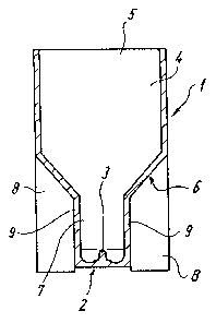
Figure 1: a longitudinal section through a measuring vessel shown
as viewed from the front;
Figure 2: a side view of the measuring vessel;
Figure 3: a plan view of the measuring vessel.
A measuring vessel 1 that is shown in the drawings is configured
to be approximately block-shaped and has a shaft 4 that is of
rectangular cross-section, one end of said shaft forming the
inlet opening 5 of the measuring vessel 1, through which the
liquid that is to be analyzed can be introduced.
The end area that is opposite the inlet opening 5 is configured
as a funnel 6 and this opens out into a tubular section 7 that is
closed off by a bottom 2.
A limiting stud 3 that extends inwards is moulded into the centre
of the bottom 2.
In the present embodiment, the tubular section 7 is configured
with a rectangular cross-section, the opposite sides 9 of which
are parallel to each other and which, in the inside area, do not
4


~ t
a.l ~~ o.,ri ?.~ ;.~
extend to the whole length. In the lower end area that is
associated with the bottom 2, the tubular section 7 is
cylindrical. The bottom 2 is formed as a trough between the
limiting stud 3 and the encircling cylindrical side wall and thus
forms the track for a ball (not shown herein) that serves to
measure blood coagulation by the ball method.
The inside diameter of the bottom 2 or of the tubular section 7,
respectively, corresponds to the inside width of the overall
measuring vessel 1, so that the inside side lengths of the
tubular section 7 that is of rectangular cross-section also
correspond to this dimension.
The increased stability of the measuring vessel, which is
extremely important, especially when the vessel is moved
automatically within an analysis machine, is achieved by the
moulded-on foot surfaces 8.
These foot surfaces are provided on both wide sides of the
measuring vessel 1, the foot surfaces 8 that are arranged on the
right and left of the tubular section 7 together with the
associated side surfaces of the tubular section 7 and the side
surfaces of the shaft 4 that are adjacent above this together
forming a wide side of the measuring vessel 1.

REFERENCE FIGURES
1 measuring vessel
2 bottom
3 limiting stud
4 shaft
in7.et opening
6 funnel
? tubular section
8 foot surfaces
9 side surfaces
6

Representative Drawing
A single figure which represents the drawing illustrating the invention.
Administrative Status

For a clearer understanding of the status of the application/patent presented on this page, the site Disclaimer , as well as the definitions for Patent , Administrative Status , Maintenance Fee  and Payment History  should be consulted.

Administrative Status

Title Date
Forecasted Issue Date 2003-01-07
(22) Filed 1993-02-24
(41) Open to Public Inspection 1993-08-26
Examination Requested 1999-12-17
(45) Issued 2003-01-07
Deemed Expired 2005-02-24

Abandonment History

There is no abandonment history.

Payment History

Fee Type Anniversary Year Due Date Amount Paid Paid Date
Application Fee $0.00 1993-02-24
Registration of a document - section 124 $0.00 1993-09-21
Maintenance Fee - Application - New Act 2 1995-02-24 $100.00 1994-12-29
Maintenance Fee - Application - New Act 3 1996-02-26 $100.00 1996-02-07
Maintenance Fee - Application - New Act 4 1997-02-24 $100.00 1997-02-06
Maintenance Fee - Application - New Act 5 1998-02-24 $150.00 1998-02-05
Maintenance Fee - Application - New Act 6 1999-02-24 $150.00 1999-02-04
Request for Examination $400.00 1999-12-17
Maintenance Fee - Application - New Act 7 2000-02-24 $150.00 2000-02-24
Maintenance Fee - Application - New Act 8 2001-02-26 $150.00 2001-02-07
Maintenance Fee - Application - New Act 9 2002-02-25 $150.00 2002-02-25
Final Fee $300.00 2002-10-15
Maintenance Fee - Patent - New Act 10 2003-02-24 $200.00 2003-02-04
Owners on Record

Note: Records showing the ownership history in alphabetical order.

Current Owners on Record
HEINRICH AMELUNG GMBH
Past Owners on Record
AMELUNG, ROLF
Past Owners that do not appear in the "Owners on Record" listing will appear in other documentation within the application.
Documents

To view selected files, please enter reCAPTCHA code :


To view images, click a link in the Document Description column. To download the documents, select one or more checkboxes in the first column and then click the "Download Selected in PDF format (Zip Archive)" or the "Download Selected as Single PDF" button.

List of published and non-published patent-specific documents on the CPD .

If you have any difficulty accessing content, you can call the Client Service Centre at 1-866-997-1936 or send them an e-mail at CIPO Client Service Centre.


Document
Description 
Date
(yyyy-mm-dd) 
Number of pages   Size of Image (KB) 
Claims 1994-04-01 2 69
Cover Page 1994-04-01 1 23
Description 1994-04-01 7 246
Cover Page 2002-12-03 1 36
Representative Drawing 2002-04-05 1 4
Claims 2002-02-13 2 50
Abstract 1994-04-01 1 25
Drawings 1994-04-01 1 12
Description 2002-02-13 7 228
Representative Drawing 1999-08-04 1 4
Correspondence 2002-10-15 1 37
Assignment 1993-02-24 9 329
Prosecution-Amendment 1999-12-17 1 41
Prosecution-Amendment 2000-05-18 1 31
Prosecution-Amendment 2002-02-13 6 162
Prosecution-Amendment 2001-10-15 2 40
Fees 2002-02-25 1 37
Fees 1997-02-06 1 30
Fees 1996-02-07 1 35
Fees 1994-12-29 1 33
Fees 1997-02-07 1 38
Fees 1996-01-24 1 44
Fees 1995-09-08 1 22

Biological Sequence Listings

Choose a BSL submission then click the "Download BSL" button to download the file.

If you have any difficulty accessing content, you can call the Client Service Centre at 1-866-997-1936 or send them an e-mail at CIPO Client Service Centre.

Please note that files with extensions .pep and .seq that were created by CIPO as working files might be incomplete and are not to be considered official communication.

No BSL files available.