Sélection de la langue

Search

Sommaire du brevet 2090263 

Énoncé de désistement de responsabilité concernant l'information provenant de tiers

Une partie des informations de ce site Web a été fournie par des sources externes. Le gouvernement du Canada n'assume aucune responsabilité concernant la précision, l'actualité ou la fiabilité des informations fournies par les sources externes. Les utilisateurs qui désirent employer cette information devraient consulter directement la source des informations. Le contenu fourni par les sources externes n'est pas assujetti aux exigences sur les langues officielles, la protection des renseignements personnels et l'accessibilité.

Disponibilité de l'Abrégé et des Revendications

L'apparition de différences dans le texte et l'image des Revendications et de l'Abrégé dépend du moment auquel le document est publié. Les textes des Revendications et de l'Abrégé sont affichés :

  • lorsque la demande peut être examinée par le public;
  • lorsque le brevet est émis (délivrance).
(12) Brevet: (11) CA 2090263
(54) Titre français: RECIPIENT DE MESURAGE
(54) Titre anglais: MEASURING VESSEL
Statut: Périmé et au-delà du délai pour l’annulation
Données bibliographiques
(51) Classification internationale des brevets (CIB):
  • G01N 1/00 (2006.01)
  • G01N 21/03 (2006.01)
  • G01N 33/49 (2006.01)
(72) Inventeurs :
  • AMELUNG, ROLF (Allemagne)
(73) Titulaires :
  • HEINRICH AMELUNG GMBH
(71) Demandeurs :
  • HEINRICH AMELUNG GMBH (Allemagne)
(74) Agent: SMART & BIGGAR LP
(74) Co-agent:
(45) Délivré: 2003-01-07
(22) Date de dépôt: 1993-02-24
(41) Mise à la disponibilité du public: 1993-08-26
Requête d'examen: 1999-12-17
Licence disponible: S.O.
Cédé au domaine public: S.O.
(25) Langue des documents déposés: Anglais

Traité de coopération en matière de brevets (PCT): Non

(30) Données de priorité de la demande:
Numéro de la demande Pays / territoire Date
P 42 05 618.7-52 (Allemagne) 1992-02-25

Abrégés

Abrégé anglais


A measuring vessel for holding liquids such as blood,
blood plasma, or the like that are to be analyzed. The
measuring vessel incorporates a shaft that is of rectangular
cross-section. One end of this shaft forms an inlet opening
and the opposite end area is formed as a funnel that opens out
into a tubular section. The tubular section incorporates at
least two parallel side surfaces that extend to almost the whole
length and the end of the tubular section is closed off by a
bottom. The wide sides of the shaft that extend parallel to
each other each form a flat contact surface. There is a part
of foot elements connected with the tubular section on which
the measuring vessel can be stood. The bottom of the tubular
section is formed with a circular internal base area and a
central stud which foams a track for a ball with the help of
which the coagulating characteristics of blood can be measured.

Revendications

Note : Les revendications sont présentées dans la langue officielle dans laquelle elles ont été soumises.


CLAIMS:
1. ~A measuring vessel for containment of liquids to
be tested comprising:
a rectangular well having one end defining an
inlet opening and another end configured in form of a
funnel, said well including parallel broadsides, each of
which forming a planar contact surface;
a tubular member having one end connected to said
funnel-shaped end of said well and another end closed by a
cylindrical bottom with a projecting central limiter pin to
define a track for a spherical body for allowing
determination of a coagulation behavior of the liquid, said
tubular member being defined by a length and including at
least two parallel side faces extending over a major portion
of the length of said tubular member; and
support means connected to said tubular member for
enabling a secure placement of the measuring vessel.
2. ~A measuring vessel as defined in claim 1 wherein
said tubular member is of square cross section.
3. ~A measuring vessel as defined in claim 1 wherein
said cylindrical bottom has an inside diameter and said
tubular member has a inner side length, said inside diameter
of said bottom corresponding to the inner side length of
said tubular member.
4. ~A measuring vessel as defined in claim 1 wherein
said support means includes a lateral footing in
prolongation of each broadside of said well.
7

5. A measuring vessel as defined in claim 1 wherein
each of said broadsides of said well defines an outer edge,
said support means extending to said outer edge of said
broadsides.
6. A measuring vessel as defined in claim 1 wherein
said support means extends slightly beyond said bottom.
7. A measuring vessel as defined in claim 1 wherein
said support means extends planar with said broadsides of
said well.
8

Description

Note : Les descriptions sont présentées dans la langue officielle dans laquelle elles ont été soumises.

A MEASURING VESSEL
23724-205
The present invention relates to a measuring vessel
for holding liquids such as blood, blood plasma, or the like
that: are to be analyzed, this having in its circular base area
a projecting limiting stud that is centrally arranged, the
vessel having a bottom forming a track for a ball, with the
help of which the coagulating characteristics of blood can be
measured.
A measuring vessel of this kind is described in
DE-PS 29 37 195.
By using the measuring vessel that is shown and
described therein, it is possible to carry out a very precise
mechanical determination of the coagulating behaviour of blood.
Tn addition to this method of examination, very
frequently a process is used that makes it possible to carry out
measurements ors blood, blood plasma, or the like, using photo-
metric methods.
Since, in order to do this, it is absolutely essential
that the light that is emitted from a sender unit can pass
unhindered through the walls of the measuring vessel, a
measuring vessel of this kind is not suitable for photometric
analysis because of its cylindrical form. Because of the
curvature of the walls of this vessel, the beam of light that
passes through the measuring vessel is deflected and, in some
cases, this could lead to imprecise measurement.
In addition, using this known measuring vessel, the
conduct of automatic analysis may be incomplete and very
1

CA 02090263 2002-02-13
23724-205
difficult. In particular, the cylindrical shape of the
measuring vessel is unsuitable for photometric measurements,
for precise positioning relative to the sender unit is a
prerequisite for accurate measurement.
However, the cylindrical shape is not only a
hindrance to automatic feed motion; it also hinders optimal
positioning in a supply container that is fitted by the
manufacturer with a plurality of measuring vessels and
delivered, complete, to the user's automatic machinery,
within which the particular measuring vessel is removed
automatically from the supply container. It then becomes
important to make optimal use of the storage space within
the supply container, i.e., to be able to accommodate the
largest possible number of measurement vessels. Naturally,
a cylindrical shape is not suitable for this purpose.
For this reason, it is the task of the present
invention to so configure a measurement vessel of this kind
such that both mechanical measurement using the ball method
and photometric measurement of the liquids that are to be
examined is made possible, and such that automatic feed into
an analysis apparatus is possible with the optimal use of a
supply container.
According to the present invention, there is
provided a measuring vessel for containment of liquids to be
tested comprising: a rectangular well having one end
defining an inlet opening and another end configured in form
of a funnel, said well including parallel broadsides, each
of which forming a planar contact surfaced a tubular member
having one end connected to said funnel-shaped end of said
2

CA 02090263 2002-02-13
23724-205
well and another end closed by a cylindrical bottom with a
projecting central limiter pin to define a track for a
spherical body for allowing determination of a coagulation
behavior of the liquid, said tubular member being defined by
a length and including at least two parallel side faces
extending over a major portion of the length of said tubular
member; and support means connected to said tubular member
for enabling a secure placement of the measuring vessel.
Using a measurement vessel that is configured in
this way, it is now possible to carry out photometric
analyses over the whole spectral range, in particular for
chromogenic substrates, enzyme kinetic and end-point
analyses.
Whereas at least two opposing and parallel side
surfaces extend to almost the whole length of the tubular
section, the side area of the tube that is adjacent to the
bottom is of a cylindrical shape.
Thus, the area that lies above the limiting stud
can be used for photometric analyses. In contrast to this,
the lower base area is used for examination using the ball
method.
2a

In addition to its possibilities for combined use, in relation to
the different measuring methods, this measurement vessel provides
the added advantage that it can be used in the course of
automatic analyses.
The rectangular plan view permits optimal arrangement within a
supply container within which a plurality of the these
essentially black-shaped measurement vessels are stored and which
is to be positioned within an analysis machine for automatic
delivery of the measurement vessels. When this is done, in each
instance, two supply containers lie with the fiat locating
surfaces that face each other, and which are formed by the broad
sides of the shaft that extend parallel to each other, adjacent
to each other.
Because of the rectangular plan shape of the supply container, on
the one hand, and because of the foot element that is provided
and which, in a preferred embodiment of the measurement vessel,
is formed from the foot surfaces that extend at the sides of the
tubular section in narrower sections of the wide side of the
shaft, it is possible to achieve exact positioning and safe
removal of the measuring vessel from the supply container, in
which connection the foot element ensures a good support when it
is removed.
The measurement vessel is of transparent plastic. Since, for
reasons of manufacturing technology, the lug is located on the
outside of the bottom of the measuring vessel, it is important
that the foot surfaces extend slightly beyond the bottom so that
this lug does not get hooked up during removal from the supply
container.
In order to provide better support for the measurement vessels
relative to each other, the present invention also provides for
the fact that the foot surfaces extend in the same plane as the
3

2~~~~'j
wide sides so that for all practical purposes one contact surface
is formed along the whole wide side of the measuring vessel.
For the remainder, in order to ensure the smooth conduct of an
automatic process, it is important that the measurement vessel be
configured so as to be symmetrical.
Other advantageous configurations of the present invention are
described in the sub-claims.
One embodiment of the present invention is described in greater
detail below on the basis of the drawings appended hereto. These
drawings show the following:
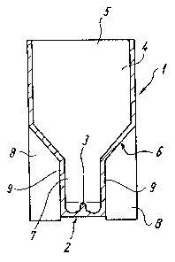
Figure 1: a longitudinal section through a measuring vessel shown
as viewed from the front;
Figure 2: a side view of the measuring vessel;
Figure 3: a plan view of the measuring vessel.
A measuring vessel 1 that is shown in the drawings is configured
to be approximately block-shaped and has a shaft 4 that is of
rectangular cross-section, one end of said shaft forming the
inlet opening 5 of the measuring vessel 1, through which the
liquid that is to be analyzed can be introduced.
The end area that is opposite the inlet opening 5 is configured
as a funnel 6 and this opens out into a tubular section 7 that is
closed off by a bottom 2.
A limiting stud 3 that extends inwards is moulded into the centre
of the bottom 2.
In the present embodiment, the tubular section 7 is configured
with a rectangular cross-section, the opposite sides 9 of which
are parallel to each other and which, in the inside area, do not
4

~ t
a.l ~~ o.,ri ?.~ ;.~
extend to the whole length. In the lower end area that is
associated with the bottom 2, the tubular section 7 is
cylindrical. The bottom 2 is formed as a trough between the
limiting stud 3 and the encircling cylindrical side wall and thus
forms the track for a ball (not shown herein) that serves to
measure blood coagulation by the ball method.
The inside diameter of the bottom 2 or of the tubular section 7,
respectively, corresponds to the inside width of the overall
measuring vessel 1, so that the inside side lengths of the
tubular section 7 that is of rectangular cross-section also
correspond to this dimension.
The increased stability of the measuring vessel, which is
extremely important, especially when the vessel is moved
automatically within an analysis machine, is achieved by the
moulded-on foot surfaces 8.
These foot surfaces are provided on both wide sides of the
measuring vessel 1, the foot surfaces 8 that are arranged on the
right and left of the tubular section 7 together with the
associated side surfaces of the tubular section 7 and the side
surfaces of the shaft 4 that are adjacent above this together
forming a wide side of the measuring vessel 1.

REFERENCE FIGURES
1 measuring vessel
2 bottom
3 limiting stud
4 shaft
in7.et opening
6 funnel
? tubular section
8 foot surfaces
9 side surfaces
6

Dessin représentatif
Une figure unique qui représente un dessin illustrant l'invention.
États administratifs

2024-08-01 : Dans le cadre de la transition vers les Brevets de nouvelle génération (BNG), la base de données sur les brevets canadiens (BDBC) contient désormais un Historique d'événement plus détaillé, qui reproduit le Journal des événements de notre nouvelle solution interne.

Veuillez noter que les événements débutant par « Inactive : » se réfèrent à des événements qui ne sont plus utilisés dans notre nouvelle solution interne.

Pour une meilleure compréhension de l'état de la demande ou brevet qui figure sur cette page, la rubrique Mise en garde , et les descriptions de Brevet , Historique d'événement , Taxes périodiques et Historique des paiements devraient être consultées.

Historique d'événement

Description Date
Inactive : CIB de MCD 2006-03-11
Le délai pour l'annulation est expiré 2005-02-24
Lettre envoyée 2004-02-24
Accordé par délivrance 2003-01-07
Inactive : Page couverture publiée 2003-01-06
Inactive : Taxe finale reçue 2002-10-15
Préoctroi 2002-10-15
Un avis d'acceptation est envoyé 2002-04-15
Lettre envoyée 2002-04-15
Inactive : Approuvée aux fins d'acceptation (AFA) 2002-04-04
Modification reçue - modification volontaire 2002-02-13
Inactive : Dem. de l'examinateur par.30(2) Règles 2001-10-15
Modification reçue - modification volontaire 2000-05-18
Lettre envoyée 2000-01-25
Inactive : Renseign. sur l'état - Complets dès date d'ent. journ. 2000-01-25
Inactive : Dem. traitée sur TS dès date d'ent. journal 2000-01-25
Exigences pour une requête d'examen - jugée conforme 1999-12-17
Toutes les exigences pour l'examen - jugée conforme 1999-12-17
Demande publiée (accessible au public) 1993-08-26

Historique d'abandonnement

Il n'y a pas d'historique d'abandonnement

Taxes périodiques

Le dernier paiement a été reçu le 2002-02-25

Avis : Si le paiement en totalité n'a pas été reçu au plus tard à la date indiquée, une taxe supplémentaire peut être imposée, soit une des taxes suivantes :

  • taxe de rétablissement ;
  • taxe pour paiement en souffrance ; ou
  • taxe additionnelle pour le renversement d'une péremption réputée.

Veuillez vous référer à la page web des taxes sur les brevets de l'OPIC pour voir tous les montants actuels des taxes.

Historique des taxes

Type de taxes Anniversaire Échéance Date payée
TM (demande, 5e anniv.) - générale 05 1998-02-24 1998-02-05
TM (demande, 6e anniv.) - générale 06 1999-02-24 1999-02-04
Requête d'examen - générale 1999-12-17
TM (demande, 7e anniv.) - générale 07 2000-02-24 2000-02-24
TM (demande, 8e anniv.) - générale 08 2001-02-26 2001-02-07
TM (demande, 9e anniv.) - générale 09 2002-02-25 2002-02-25
Taxe finale - générale 2002-10-15
TM (brevet, 10e anniv.) - générale 2003-02-24 2003-02-04
Titulaires au dossier

Les titulaires actuels et antérieures au dossier sont affichés en ordre alphabétique.

Titulaires actuels au dossier
HEINRICH AMELUNG GMBH
Titulaires antérieures au dossier
ROLF AMELUNG
Les propriétaires antérieurs qui ne figurent pas dans la liste des « Propriétaires au dossier » apparaîtront dans d'autres documents au dossier.
Documents

Pour visionner les fichiers sélectionnés, entrer le code reCAPTCHA :


Pour visualiser une image, cliquer sur un lien dans la colonne description du document. Pour télécharger l'image (les images), cliquer l'une ou plusieurs cases à cocher dans la première colonne et ensuite cliquer sur le bouton "Télécharger sélection en format PDF (archive Zip)" ou le bouton "Télécharger sélection (en un fichier PDF fusionné)".

Liste des documents de brevet publiés et non publiés sur la BDBC .

Si vous avez des difficultés à accéder au contenu, veuillez communiquer avec le Centre de services à la clientèle au 1-866-997-1936, ou envoyer un courriel au Centre de service à la clientèle de l'OPIC.


Description du
Document 
Date
(aaaa-mm-jj) 
Nombre de pages   Taille de l'image (Ko) 
Page couverture 2002-12-03 1 36
Page couverture 1994-04-01 1 20
Revendications 1994-04-01 2 61
Description 1994-04-01 7 218
Dessin représentatif 2002-04-05 1 4
Revendications 2002-02-13 2 50
Abrégé 1994-04-01 1 22
Dessins 1994-04-01 1 10
Description 2002-02-13 7 210
Dessin représentatif 1999-08-04 1 4
Rappel - requête d'examen 1999-10-26 1 117
Accusé de réception de la requête d'examen 2000-01-25 1 180
Avis du commissaire - Demande jugée acceptable 2002-04-15 1 166
Avis concernant la taxe de maintien 2004-04-20 1 173
Correspondance 2002-10-15 1 37
Taxes 2002-02-25 1 37
Taxes 1994-12-29 1 38
Taxes 1997-02-06 1 34
Taxes 1996-02-07 1 40
Taxes 1997-02-07 1 43
Taxes 1996-01-24 1 50
Taxes 1995-09-08 1 25