Note: Descriptions are shown in the official language in which they were submitted.
w o 92/07618 2 0 9 0 313 PCT/US91/07876
Iontophoret1c drug dellvery electrode and method of hydrat1ng the same
TECHNICAL FIELD
s
This invention relates to a device for delivering an agent
transdermally or transmucosally by iontophoresis. More
particularly, this invention relates to an electrically powered
iontophoretic delivery device having electrodes which can be ~
o hydrated just before applying the device to the body. - -
BACK6ROUND ART
Iontophoresis, according to Dorland's Illustrated Medical
Dictionarv, is defined to be "the introduction, by means of
electric current, of ions of soluble salts into the tissues of the
body for therapeutic purposes.~ Iontophoretic devices have been
known since the early 1900's. British patent specification No.
410,009 (1934) describes an iontophoretic device which overcame
20 one of the disadvantages of such early devices known to the art at
that time, namely the requirement of a special low tension (low
voltage) source of current which meant that the patient needed to
be immobilized near such source. The device of that British
specification was made by forming a galvanic cell from the
2s electrodes and the material containing the medicament or drug to .
be delivered transdermally. The galvanic cell produced the
current necessary for iontophoretically delivering the medicament.
This ambulatory device thus permitted iontophoretic drug delivery
with substantially less interference with the patient's daily
30 activities.
. .
More recently, a number of United States patents have issued
in the iontophoresis field, indicating a renewed interest in this
mode of drug delivery. For example, U.S. Patent No. 3,991,755
35 issued to Vernon et al; U.S. Patent No. 4,141,359 issued to
Jacobsen et al; U.S. Patent No. 4,398,545 issued to Wilson; and
. ~ :. .. .. -., -, . ,. . ~ . . .. . . ..
; . ... . . . ... .. .. . . . .
, .,, -: .. , . . . . , .
.. . . .. . . . .
. .: . , , . , -
... . -. .
,.... -, , ~, ....
.. .. - . . . - . ~ :. ,:
; . . .. . .
, .. . , ,
.. ...
w o 92/07618 2 0 9 0 ~ ~ 3 PCT/US9t/07876
U.S. Patent No. 4,250,878 issued to Jacobsen disclose examples of
iontophoretic devices and some applications thereof. The
iontophoresis process has been found to be useful in the
transdermal administration of medicaments or drugs including
s lidocaine hydrochloride, hydrocortisone, fluoride, penicillin,
dexamethasone sodium phosphate, insulin and many other drugs.
Perhaps the most common use of iontophoresis is in diagnosing
cystic fibrosis by delivering pilocarpine salts iontophoretically.
The pilocarpine stimulates sweat productioni the sweat is
collected and analyzed for its chloride content to detect the
presence of the disease.
In presently known iontophoretic devices, at least two
electrodes are used. Both of these electrodes are disposed so as
to be in intimate electrical contact with some portion of the skin
of the body. One electrode, called the active or donor electrode,
is the electrode from which the ionic substance, medicament, drug
precursor or drug is delivered into the body by iontophoresis.
The other electrode, called the counter or return électrode,
20 serves to close the electrical circuit through the body. In
conjunction with the patient's skin contacted by the electrodes,
the circuit is completed by connection of the electrodes to a
source of electrical energy, e.g., a battery. For example, if the
ionic substance to be delivered into the body is positively
25 charged (i.e., a cation), then the anode will be the active
electrode and the cathode will serve to complete the circuit. If
the ionic substance to be delivered is negatively charged (i.e.,
an anion), then the cathode will be the active electrode and the
anode will be the counter electrode.
Alternatively, both the anode and cathode may be used to
deliver drugs of opposite charge into the body. In such a case,
both electrodes are considered to be active or donor electrodes.
For example, the anode can deliver a positively charged ionic
35 substance into the body while the cathode can deliver a negatively
charged ionic substance into the body.
: ,, , , , , - , . .. .
. ;, : : . . - . :
, .
. . - . .
. , . ` ::: :
- , . . . . .
- - . : .
,. , ., .. - .
... . ~ :
, , :
;~-
. - , , . ~ . . . ..
.. . . .
. . . .
- w o 92/07618 2 ~ 9 0 3 1 3 PCT/US91/07876
It is also known that iontophoretic delivery devices can be
used to deliver an uncharged drug or agent into the body. ~his is
accomplished by a process called electroosmosis. Transdermal
delivery of nonionic drugs by the phenomenon of electroosmosis is
s described by Hermann Reiss in Zeitschrift fur Bioloaie, Bd. 81, pp
125-140 (1924) and the transdermal delivery of nonionic
polypeptides by the phenomenon of electroosmosis is described in
Sibalis et al. U.S. Patent Nos. 4,878,892 and 4,940,456.
Electroosmosis is the transdermal flux of a liquid solvent (e.g.,
the liquid solvent containing the uncharged drug or agent) which
is induced by the presence of an electric field imposed across the
skin by the donor electrode. As used herein, the terms
"iontophoresis" and "iontophoretic" encompass both the delivery of
charged ions as well as the delivery of uncharged molecules by the
associated phenomenon of electroosmosis.
Iontophoretic delivery devices generally require a reservoir
or source of the beneficial agent (which is preferably an ionized
or ionizable agent or a precursor of such agent) to be
20 iontophoretically delivered or introduced into the body. Examples
of such reservoirs or sources of ionized or ionizable agents
include a pouch or cavity as described in the previously mentioned
Jacobsen U.S. Patent No. 4,250,878, a porous sponge or pad as
disclosed in Jacobsen et al. U.S. Patent No. 4,141,359, or a pre-
formed gel body as described in Webster U.S. Patent No. 4,383,529
and Ariura et al. U.S. Patent No. 4,474,570. Such drug reservoirs
are electrically connected to the anode or the cathode of an
iontophoresis device to provide a fixed or renewable source of one
or more desired agents.
3 0
- Iontophoretic delivery devices which are attachable at a
skin surface and rely on electrolyte fluids to establish
electrical contact with such skin surfaces can be divided into at
least two categories. The first category includes those devices
35 which are prepackaged with the liquid electrolyte contained in the
electrode receptacle. The second type of device uses dry-state
- - . . ~ - ,.
,. - : - ~
. , ,.. ,." . . . ~...... .: . ;., .: . ;
- , . . ~ .
: . ,~ ,: -
; . , , , ~ ~
w o 92tO7618 2 0 9 ~ 313 PCT/US91/0787~.
electrodes whose receptacles are customarily filled with liqu1d
drug/electrolyte immediately prior to application to the body.
With both types of devices, the user currently:experiences
numerous problems which make their use both ~inconvenient and .
s problematic. ~ .;`
.~ . .
With respect to the prefilled device, storage is a major
concern. Many drugs have poor stability when in solution.
Accordingly, the shelf life of prefilled iontophoretic drug
o delivery devices is unacceptably short. Corrosion of the
electrodes and other electrical components is also a potential
problem with prefilled devices. For example, the return electrode
assembly will usually contain an electrolyte salt such as sodium
chloride which over time can cause corrosion of metallic and other
S electrically conductive materials. Another problem with prefilled ~ -
electrodes concerns maintaining the electrodes sterile and
preventing microbial growth therein. This is a particular problem
when the liquid used to conduct iontophoresis is water. Although
antimicrobial agents can be added to the drug and/or electrolyte
20 reservoirs of an iontophoretic delivery device, the addition of
such agents tends to compromise the efficiency of agent delivery.
Leakage is another serious problem with prefilled iontophoretic
drug delivery devices. Leakage of drug or electrolyte from the
electrode receptacle can result in an inoperative or defective
2s state. Furthermore, such prefilled devices are difficult to apply
because the protective seal which covers the electrode opening and
retains the fluid within the receptacle cavity must be removed
prior to application on the skin. After removal of this
protective seal, spillage often occurs in attempting to place the
30 electrode on the skin. Such spillage impairs the desired adhesive
contact of the electrode to the skin and also voids a portion of
the receptacle cavity. The consequent loss of drug or~electrolyte
fluid tends to disrupt electrical contact with the electrode plate
contained therein and otherwise disrupts the preferred uniform
35 potential gradient to be applied.
, ~ ....... . . . . . . .. . .
: - , - . ,. . . : : .
.. - ~ ... . .
. . ,-
~. . .
... . ..
, : , .:. .. - .. .
..... . . .. . .
. .. . . . .
,. . . . ..
,'.:- . . . ~ , . :
w o 92/07618 2 0 9 0 3 1 3 PCTtUS91/07876
Although dry-state electrodes have numerous advantages in
ease of storage, several problems remain. For example, the drug
and electrolyte receptacles of such a device are conventionally
filled through an opening prior to application of the device to
s the patient's skin. Thereforej the same problem of spillage and
ioss of drug or electrolyte upon application occurs as with the
prefilled electrode.
Frequently, such electrodes are not well structured to -
o develop the proper uniform current flow required in iontophoresis i.
applications. Such nonuniform current flow may result from the
occurrence of air pockets within the receptacle cavity at the skin
surface. Such effects are particularly troublesome in -
iontophoresis applications, where a nonuniform current
distribution may result in excessive skin irritation or "burning".
More recently, iontophoretic delivery devices have been
developed in which the donor and counter electrode assemblies have
a "multilaminate" construction. In these devices, the donor and
20 counter electrode assemblies are each formed of multiple layers of
(usually) polymeric matrices-. For example, Parsi U.S. Patent
4,731,049 discloses a donor electrode assembly having hydrophilic
polymer based electrolyte reservoir and drug reservoir layers, a
skin-contacting hydrogel layer, and optionally one or more
25 semipermeable membrane layers. In addition, Ariura et al, U.S.
Patent 4,474,570 discloses a device wherein the electrode -
assemblies include a conductive resin film electrode layer, a
hydrophilic gel reservoir layer, an aluminum foil conductor layer
and an insulating backing-layer. .-
-. ... .. ~
The drug and electrolyte reservoir layers of iontophoretic
delivery devices have typically been formed of hydrophilic
polymers. See for example, Ariura et al, U.S. Patent 4,474,570;
~ebster U.S. Patent 4,383,529 and Sasaki U.S. Patent 4,764,164.
35 There are several reasons for using hydrophilic polymers. First,
water is a biocompatible, highly polar solvent and therefore
- . . .
.. . ", .. - , . .
: . . ~ -; . ... ~ . . .
.~ . :- . . : . , . .
;, ~. :, . . . .. . . . . . .
: .~, .. , . , ~..... - . . .. :
w o 92/07618 2 0 9 0 3 1 ~ PCT/US91/07876 ~
preferred for ionizing many drug salts. Secondly, hydrophilic
polymer components (i.e., the drug reservoir in the donor
electrode and the electrolyte reservoir in the counter electrode)
can be hydrated while attached to the body by ab$orbing water from
s the skin or from a mucosal membrane. For examp~e, skin contacting
electrodes can be hydrated by absorbing sweat~or water from
transepidermal water loss. Similarly, electrodes attached to an
oral mucosal membrane can be hydrated by absorbing saliva. Once
the drug and electrolyte reservoirs become hydrated, ions are able
o to move through the reservoirs and across the tissue, enabling the
device to deliver agent to the body. Hydrogels have been
particularly favored for use as the drug reservoir matrix and
electrolyte reservoir matrix in iontophoretic delivery devices, in
part due to their high equilibrium water content and their ability
to absorb water from the body. In addition, hydrogels tend to
have good biocompatibility with the skin and with mucosal:
membranes. However, since many drugs and certain electrode
components are unstable in the presence of water, iontophoretic
drug delivery devices having a drug reservoir formed of a
20 prehydrated hydrogel may also have-an unacceptably short shelf
life. One solution to the drug stability problem is to use
hydrophilic polymer drug and electrolyte reservoirs which are in a
substantially dry state, i.e. in a non-hydrated condition. The
drug and/or electrolyte can be dry blended with the hydrophilic
2s polymer and then cast or extruded to form a non-hydrated, though
hydratable, drug or electrolyte containing reservoir.
Unfortunately, the non-hydrated hydrophilic polymer components
must first absorb sufficient quantities of water from the body
before the device can operate to deliver drug. This delivery `~
30 start-up period can take in excess of 8 hours. This delay makes
many devices unsuited for their intended purpose: For example,
when using an iontophoretic delivery device to apply a`local~
anesthetic in preparition for a minor surgery (e.g., surgicàl
removal of a mole), the surgeon and the patient must wait until
3s the drug and electrolyte reservoirs of the delivery device become
~:.. . . . . . : ...
;, ~. t
.:,"' , '., ' '
~':. ' ' . . . - :`
. ' ' . .
WO 92/07618 2 ~ 9 0 3 1 3 PCI /US91/07876
sufficiently hydrated before the anesthetic is delivered in
sufficient quantities to induce anesthesia. Similar delays are
encountered with other drugs. -
s In response to these difficulties, Konno et al. in U.S.
Patent 4,842,577 disclose in Figure 4 an iontophoretic electrode
assembly having a substantially non-hydrated drug containing
matrix and a separate water reservoir which is initially sealed,
using a foil sheet, from the drug containing portions of the
o electrode. Unfortunately, this electrode design is not only
difficult to manufacture but also is subject to severe handling
restrictions. In particular, there is a tendency for the foil
seal to be inadvertently broken during manufacture, packaging and
handling of the electrode. This can have particularly drastic
consequences especially when the seal is broken during manufacture
of the device. Once the seal is broken, water is wicked:into the
drug-containing reservoir which can cause degradation of the drug
and/or other components before the device is ever used.
- '
Another disadvantage of using non-hydrated hydrophilic
polymer components is that they have a tendency to delaminate from
other parts of the electrode assembly during hydration. For
example, when utilizing a drug reservoir matrix or an electrolyte
reservoir matrix composed of a hydrophilic polymer, the matrix
2s begins to swell as it absorbs water from the skin. In the case of
hydrogels, the swelling is quite pronounced. Typically, the drug
or electrolyte reservoir is in either direct contact, or contact
through a thin layer of an ionically conductive adhesive, with an
electrode. Typically, the electrode is composed of metal (e.g., a
30 metal foil or a thin layer of metal deposited on a backing layer)
or a hydrophobic polymer containing a conductive filler-(e.g., a
hydrophobic polymer loaded with carbon fibers and/or metal
particles). Unlike the hydrophilic drug and electrolyte ~-
reservoirs, the electrodes do not absorb water and do not swell. `
3s The different swelling properties of the hydrophilic reservoirsand the electrodes results in shearing along their contact
. . .
:;. . ' : `
,''~: ' ''' . , : . ' .
w o 92/07618 2 ~ 9 0 3 1 3 PCT/US91/07876
surfaces. In severe cases, the shearing can result in the
complete loss of electrical contact between the electrode and the
drug/electrolyte reservoir resulting in an inoperable device.
. . .
s DISCLOSURE OF THE L~ ENTION
~ . .
Thus, it is an object of the present invention to provide an
iontophoretic drug delivery device with electrodes which are
manufactured in an initially non-hydrated or dry state but which
can be quickly hydrated prior to placement on the body.
It is another object of this invention to provide an
improved method of quickly hydrating the electrodes in an
iontophoretic delivery device in order to minimize the "start-up"
delay of an iontophoretic delivery device.
It is a further object of this invention to provide an
iontophoretic drug delivery device which cannot be inadvertently
hydrated prior to actual use.
It is a still further object of this invention to provide a
method of hydrating the hydrophilic components of a dry state
multilaminate iontophoresis electrode assembly without the ;
delamination problems encountered with the prior art electrodes.
These and other objects are met by an electrically powered
iontophoretic agent delivery device and a method of hydrating
same. In accordance with one embodiment of the invention, the
- delivery device includes at least one multilaminate dry state
30 electrode assembly and a source of electrical power which is
electrically connected to the electrode assembly. The electrode
assembly includes a reservoir layer comprised of a substantially
non-hydrated hydratable matrix adapted to contain an agent to be
delivered. The electrode assembly is adapted to be placed in
35 agent transmitting relation with a body surface, such as intact
skin or a mucosal membrane, for delivery of agent therethrough.
, ., . . , . ,... , . - . . -
.. - . . , , -,. . . .
~.. , . , ~ . ; . , - , :
.
, ~ , - - .
,~}
. .
.,: . ; - ~ : .
,-. ~ , . ~ , .
Wo 92/07618 2 0 3 0 3 1 3 PCI/US91/07876
The electrode assembly also includes an electrode layer in
electrical contact with both the power source and the reservoir
layer.
s The electrode assembly has a preformed passageway through
the electrode layer for admitting a hydrating liquid into the
substantially non-hydrated matrix. The passageway establishes
fluid communication between the exterior of the device and the
non-hydrated matrix. The electrode assembly is activated by
o introducing a liquid from an external source through the preformed
passageway and into the hydratable reservoir layer.
Preferably, the liquid comprises water. In the case of a
donor electrode assembly, the agent preferably comprises a drug.
~s In the counter electrode assembly, the agent preferably comprises
an electrolyte salt. Most preferably, both the agent and the
electrolyte salt are soluble in the liquid. The agent and/or the
electrolyte salt may be present in the non-hydrated matrix either
before hydration or maybe added to the non-hydrated matrix with
20 the liquid at the time of hydration. When the non-hydrated matrix
already contains the agent, the liquid preferably comprises
deionized water. When the non-hydrated matrix initially contains
no agent, the liquid preferably comprises an aqueous solution or
suspension of a drug or an electrolyte salt. Most preferably, the
2s matrix of the reservoir layer is comprised of a hydrophilic
polymer.
In accordance with a second embodiment of the invention, a
multilaminate dry state electrode assembly for an electrically
30 powered iontophoretic agent delivery device, and a method of
hydrating the electrode assembly, are provided. The electrode
assembly is adapted to be placed in agent transmitting relation
with a body surface such as intact skin or a mucosal membrane, for
delivery of agent therethrough. The electrode assembly inclùdes
3s an electrode layer in electrical contact with an electrical power
source and adapted to be placed in electrical contact with a
. . . . , - ~ ~ :
. , ' :. ~ '
. . . . .
.
WO 92/07618 2 ~ 9 0 3 1 3 PCI`/US91/07876
reservoir layer. The reservoir layer is adapted to contain an
agent to be delivered. The reservoir layer comprises a
substantially non-hydrated, hydratable matrix which is initially
separated from the electrode layer and the power source. The
s reservoir layer has an exposable surface for introducing a liquid
thereto in order to hydrate the reservoir layer. After hydration,
the reservoir layer is placed in electrical contact with the
electrode layer.
o Also provided is a method for hydrating the device. The
method includes separating the reservoir layer from the electrode
layer while the reservoir layer is in a substantially non-hydrated
condition. A hydrating liquid is introduced into the reservoir
layer in an amount sufficient to permit ion transport through the
reservoir layer. Thereafter, the hydrated reservoir layer is
secured in electrical contact with the electrode layer.
Preferably, the hydrating liquid comprises water. In the
case of a donor electrode assembly, the agent preferably comprises
20 a drug. In the counter electrode assembly, the agent preferably
comprises an electrolyte salt. Most preferably, both the agent
and the electrolyte salt are soluble in the liquid. The agent
and/or the electrolyte salt may be present in the non-hydrated
matrix either before hydration or may be added to the non-hydrated
2s matrix with the liquid at the time of hydration. When the non-
hydrated matrix already contains the agent, the liquid preferably
comprises deionized water. When the non-hydrated ma~rix initially
contains no agent, the liquid preferably comprises an aqueous
solution or suspension of a drug or an electrolyte salt. Most
30 preferably, the matrix of the reservoir layer is a hydrophilic
polymer. This embodiment of the invention has particular utility
where the hydrophilic polymer has a tendency to swell upon
hydration. Most preferably, the hydrated reservoir layer is
secured in electrical contact with the electrode layer after the
3s swelling of the reservoir layer is substantially complete.
- - , - :
, , , ~ . - : ,
. .. .
. ~ .
.. . .
., .. . ~ - .. , ~ ..
:..................................... . .
w o 92/07618 2 0 9 0 3 1 3 PCTIUS91/07876
BRIEF DESCRIPTION OF THE DRAWINGS
Figure 1 is a schematic side view of an iontophoretic drug
s delivery device according to the present invention;
Figure 2 is a schematic top view of the device shown in
Figure I;
Figure 3 is a schematic top view of another embodiment of an
iontophoretic delivery device according to the present invention;
Figure 4 is a schematic end view of the device shown in
Figure 3, after assembly; and
Figure S is a schematic side view of another embodiment of
an iontophoretic delivery device according to the present
invention.
In the figures, like elements are designated by the same
reference number in the several drawings. ~-
'' . - `, ':
MODES FOR CARRYING OUT THE INVENTION `
.: ': '
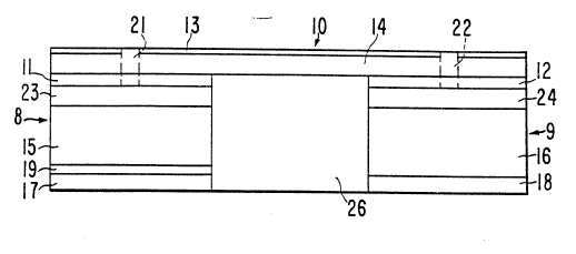
Figure 1 is a schematic view of an iontophoretic delivery - `
device 10 for delivering a beneficial agent through a body surface
such as intact skin or a mucosal membrane. Iontophoretic delivery
device 10 includes a donor electrode assembly 8 and a counter
electrode assembly 9. The dono~ electrode assembly 8 and the
30 counter electrode assembly 9 are physically attached to insulator -
26 and form a single self-contained unit.~ Insulator 26 prevents
the electrode assemblies 8 and 9 from short circuiting the body by - -~
preventing electrical and/or ion transport between the electrode
assemblies 8 and 9. Electrode assemblies 8 and-9 are connected in
35 series, by appropriate electrical conductors, with an electrical
power source. The power source and the electrical conductors are
`, '.
. !- . . ~ , . , : - : . ~ . .
'', . : . ,, . ', ': :' . ': . . ., ,' ' - ' ' . : . : ~
tr., , ,, , . . . ~ . - :. -; . ~ ' . : .
~i?: ; - -
w o 92/07618 2 ~ 9 ~ ~ 1 3 PCT/US91/07876
schematically shown as layer 14. The power source used to power
device 10 is typically one or more low voltage batteries. A water
impermeable backing layer 13 preferably covers layer 14 with its
associated electrical components. -
s ~ i.
~ he donor electrode assembly 8 i~ncludes an electrode layer11 and a reservoir layer 15. The reservoir 15 contains the
beneficial agent to be iontophoretically delivered by device 10.
A rate controlling membrane layer 19 is optionally positioned
o between the reservoir layer 15 and the body surface for
controlling the rate at which the agent is delivered to the body
surface or for preventing the delivery of agent to the body
surface when the device is turned off. Counter electrode assembly
9 contacts the body surface at a location spaced apart from
s electrode assembly 8. Counter electrode assembly 9 includes an
electrode layer 12 and a reservoir layer 16. Device 10 can be
adhered to the body surface by means of ion-conducting adhesive
layers 17 and 18. As an alternative to the ion-conducting -~
adhesive layers 17 and 18 shown in Figure 1, device 10 may be
20 adhered to the body surface using an adhesive overlay. Any of the
conventional adhesive overlays used to secure passive transdermal
delivery devices to the skin may be used.
When the device 10 is in storage, no current flows because
25 the device does not form a closed circuit. When the device 10 is
placed on the skin or mucosal membrane of a patient and the
electrode assemblies 8 and 9 are sufficiently hydrated to allow
ions to flow through the various layers of electrode assemblies 8
and 9, the circuit between the electrodes is closed and the power
30 source begins to deliver current through the device and through
the body of the patient. ,The donor and counter electrode -
- assemblies 8 and 9 normally-include a strippable release liner,
not shown, which is removed prior to application of electrode- -
assemblies 8 and 9 to a body surface.
. .:
.
.`' ` ,, ', ' ' '.' , , - ., ,., ,~ ~ . ,' .
~' . ~ . . .. . ..
'" :'
,
:, , ,, ,::.
::
,: . :
WO 92/07618 2 0 9 0 31 ~ PCr/US91/07876
As shown in Figures 1 and 2, the donor electrode assembly 8
includes a preformed passageway 21 extending through the
impermeable backing layer 13, the electronic component layer 14
- and the donor electrode layer 11. The donor electrode assembly 8
s optionally includes a layer 23 of a liquid-wicking material. Any
liquid introduced through passageway 21 is quickly absorbed by
layer 23 and wicked across the entire top surface of agent
reservoir 15. Preferably, the passageway 21 is also filled with a
similar liquid-wicking material. The passageway 21, optionally
o with the wicking layer 23, enables a liquid to be introduced
throùgh passageway 21 from the exterior of device 10 directly into
the matrix of reservoir layer 15 in order to hydrate the matrix
and optionally to hydrate the layers 23, 19 and/or 17 if they are
present, and to activate the donor electrode assembly 8. In most
cases the liquid used to hydrate the matrix of reservoir 15 will
be water, but other liquids including non-aqueous liquids, can ~
also be used to "hydrate" (i.e., activate) the matrix of reservoir ~ -
layer 15. In the typical case where the liquid is water, the ~ -
matrix of reservoir layer 15 will be at least partly composed of a ~- -
20 hydrophilic material such as a hydrophilic polymer, a cellulosic
sponge or pad, or other water retaining material. Most
preferably, the matrix of reservoir layer 15 will be at least
partly composed of a hydrophilic polymer of the type described
hereinafter.
2s
As an alternative to the wicking layer 23, the top surface
of reservoir 15 may be provided with a plurality of grooves 30 in
fluid communication with passageway 21. Grooves 30 distribute any
liquid introduced through passageway 21 across the upper surface
of reservoir 15. 6rooves 30 are shown schematically in Figure 2.
Similarly, a preformed passageway Z2 extends through -the
electrode layer 12, the electronic component layer 14 and the
impermeable backing layer 13. An optional liquid wicking layer 24 ! ~
35 may be provided between reservoir 16 and electrode 12 in counter -
electrode assembly 9. ~icking layer 24 has a similar function to
,~ . , , , . ,. ,, . : .
';, - . . - . .. . .
. - . . , , . - , .
: :.~. . : ,, .:, ,
...... . . . - ... . . . .
w o 92/07618 2 0 9 0 31 3 PCT/US91/0787~-
wicking layer 23 in the donor electrode assembly 8. Passageway 22
and wicking layer 24 establish fluid communication between the
exterior of device 10 and the non-hydrated matrix of reservoir
layer 16. The passageway 22, optionally with the wicking layer
s 24, enables a liquid to be introduced through passageway 22 from
the exterior of device 10 directly into the matrix of reservoir
layer 16 in order to hydrate the matrix, and optionally to hydrate
the layers 24 and/or 18 if there are present, and to activate the
counter electrode assembly 9. As with the donor electrode
assembly 8, the liquid used to hydrate the matrix of reservoir
layer 16 will typically be water, although other liquids including
non-aqueous liquids, can also be used. As an alternative to layer
24, the top surface of electrolyte reservoir layer 16 may be
provided with a plurality of grooves similar to grooves 30 shown
in reservoir layer 15.
Preferably, as shown in Figure 5, removable plugs 31 and 32
are provided to seal the openings to passageways 21 and 22,
respectively. Plugs 31 and 32 may be formed of a material such as
20 wax, rubber, polymer resin or a similar material which is
effective to form a seal with passageways 21 and 22. Most
preferably, plugs 31 and 32 form a water-tight seal with
passageways 21 and 22, respectively. Plugs 31 and 32 help prevent
evaporative liquid loss from the hydrated layers 15, 16, 17, 18,
2s 19, 23 and 24 and thereby prevents these layers from drying out.
Plugs 31 and 32 also enable device 10 to be worn on the body
without danger of admitting liquids, such as ordinary tap water
from bathing? containing extraneous ions or other contaminants
into the reservoir layers 15 and 16.
. .
In accordance with the present invention, at least one of
electrode assemblies 8 and 9, and preferably both electrode
assemblies 8 and 9 are initially in a substantially dry state.
Thus, the various ion transporting layers making up electrode
35 assemblies 8 and 9 are initially in a non-hydrated condition. As
used herein, the terms ~dry state" and "non-hydrated" mean that
, . . . . . ..
...... . ..
: . .
: . . .. :- :
~ .... . :. ; . --
:, : ; .: : . - . .:
. . . . . .
.. . .. .
w o 92/07618 2 ~ 9 0 313 PCT/US91/078~6
the particular layer contains an insufficient amount of liquid to
permit ion transport therethrough. For example, the ion
transmitting layers of donor electrode assembly 8 include
reservoir layer 15 and optional layers 17, 19 and 23. In order
s for donor electrode assembly 8 to be considered a "dry state"
electrode, none of layers 15, 17, 19 and 23 are sufficiently
hydrated to allow ion transport therethrough.
Similarly, in order for counter electrode assembly 9 to be
considered a "dry state" electrode, neither reservoir layer 16 nor
optional layers 18 and 24 contains sufficient liquid to allow ion
transport therethrough. ;
In order to be considered ~non-hydrated," reservoir layers
S 15 and 16 should generally contain less than about 10 wt% liquid, .
preferably less than about 5 wt% liquid and most preferab]y less
than about 1 wt% liquid.
In order to activate delivery device 10, reservoir layers 15
and 16, as well as the optional adhesive layers 17 and 18 and
membrane layer 19, must become sufficiently hydrated to enable
agent to be transported therethrough by iontophoresis. In order
to hydrate reservoir layers 15 and 16, as well as the optional
adhesive layers 17 and 18 and membrane layer 19, a liquid
2s (typically water) is introduced through passageways 21 and 22. As
shown in Figures 1 and 2, passageways 21 and 22 pass completely
through the outer backing layer 13, the electronic component layer
14 and the electrode layers 11 and 12, respectively. Thus, the
liquid can be introduced into passageways 21 and 22 simply by --
30 pouring the liquid directly into the openings of passageways 21
and 22 in the top of the device 10.
In most cases, the liquid introduced into device 10 through
passageways 21 and 22 will be composed at least in part of water.
35 However, it is well within the scope of the present invention to
~hydrate" the reservoir layers 15 and 16 using other liquids
~. . . -: , . . . .. .. . . . .. . .
,.; . ....... . , . :
: . . .
..;.
.. . .
.~ ; . .
;. . . ~
WO 92/07618 2 ~ 9 0 31~ PCI/US91/0787~
16
including non-aqueous liquids such a alcohols and glycols.
Accordingly, as used herein, the term "hydrate" refers to the
addition of either aqueous or non-aqueous based liquids through
passageways 21 and 22. Furthermore, in those instances where the
s non-hydrated reservoir layers 15 and/or 16 initially contain no
drug or electrolyte, the hydrating liquid may co0prise a liquid
solution or suspension of the drug or electrolyte.
Turning now to Figures 3 and 4, there is shown an alternate
o embodiment of an iontophoretic agent delivery device, designated
by the numeral 20, according to the present invention. Figure 3
shows the structure of device 20 while in its initial non-hydrated
condition. Reservoir layers 15 and 16 are separated from their
respective electrode layers 11 and 12 and the electronic component
layer 14. Thus, initially device 20 is separated into two parts.
The left hand part includes the electronic component layer 14 and
the electrode layers 11 and 12, all of which are laminated onto a
sheet 27 of a preferably water impermeable backing material. The
right side of device 20 includes reservoir layers 15 and 16
20 separated by insulator 26 and optionally ion-conducting adhesive
layers 17 and 18, membrane layer 19 and wicking layers 23 and 24,
all of which are laminated onto sheet 28, also of a preferably
water impermeable backing material. A weakened score line 35
divides sheet 27 from sheet 28. As shown in Figure 3, release
2s liners 33 and 34 are provided to cover the reservoir layers 15 and
16, respectively.
Device 20 is manufactured with reservoir layers 15 and 16,
along with any optional wicking layers, membrane layers and/or ion
30 conducting adhesive layers, in a substantially non-hydrated -~-
condition. When devlce 20 is ready to be used, the release liners
33 and 34 are removed, thereby exposing reservoir layers 15 and
16. A hydrating liquid is then poured directly onto reservoir
layers 15 and 16. Optionally, a wicking material, or liquid
3s carrying grooves (not shown in Figure 3) can be provided on the
top surface of either or both of reservoir layers 15 and 16.
.... .... . " " ,.. . . ... ....
.. ..
,, . . ., . , ~ .
, , ,
.,.. ~: . .. - ... .
.,.", ` ' :
, . , : . .
i,~, ~ ' ''' ., : .
w o 92/07618 2 0 9 0 3 1 3 PCT/~S91/07876
In this embodiment, reservoir layers 15 and 16 are
preferably comprised of a material which becomes tacky once
hydrated, e.g., a tacky hydrogel. Alternatively, the top surface
of reservoir layers 15 and 16 can also be coated with a water-
s conducting and ion-conducting adhesive layer.
Once reservoir layers 15 and 16 become sufficiently hydrated
to allow agent transport therethrough, sheet 28 is separated from
sheet 27 by tearing along score line 35. The right side of the - .
device is then placed directly over the left side of the device
such that the reservoir layer 15 is in electrical contact with
electrode layer 11 and the reservoir layer 16 is in electrical -
contact with electrode layer 12. Electrical contact between
reservoir layers 15 and 16 and electrode layers 11 and 12,
respectively, is maintained due to the tacky nature of layers 15
and 16, or alternatively by an adhesive applied on the top
surfaces of layers 15 and 16. Thereafter, sheet 28 is removed and
the device 20 is placed on a body surface 100 as shown in Figure
4. Figure 4 is an end view of device 20 and accordingly shows
. 20 only the layered configuration of the ~donor" electrode assembly. -~
It will be understood that device 20, in its assembled condition,
likewise contains an insulator 26 and a counter electrode assembly
9 similar to that shown in Figure 1. .~ .
..
Device 20 illustrated in Figures 3 and 4 has particular
utility when the matrices of reservoir layers 15 and 16 are
composed, in whole or in part, of a hydrophilic material having a
tendency to swell as it absorbs the hydrating liquid. This
embodiment has particular advantage when using hydrophilic
30 - hydrogels as the matrices of reservoir layers 15 and 16, since
hydrogels have a tendency to swell during hydration. Most
preferably, the right side of device 20 is secured over the left
side of device 20 after reservoir layers 15 and 16 have been I ;
completely hydrated and are no longer swelling.
.: .:
.: . . .
.': .' ' , ' ,' : ,, .' ` - .:
''',, . ~ ~'' , . .,, :-' .
2~90313
w o 92/07618 PCT/US91/07876-
.
~.18
When used in connection with the reservoir 15 or the donor
electrode assembly 8, the term "agent" refers to beneficial
agents, such as drugs, within the class which can be delivered
through body surfaces. The expression "drug" is intended to have
s a broad interpretation as any therapeutically active substance
which is delivered to a living organism to produce a desired,
usually beneficial, effect. In general, this includes therapeutic
agents in all of the major therapeutic areas including, but not
limited to, anti-infectives such as antibiotics and antiviral
agents, analgesics and analgesic combinations, anesthetics,
anorexics, antiarthritics, antiasthmatic agents, anticonvulsants,
antidepressants, antidiabetic agents, antidiarrheals,
antihistamines, anti-inflammatory agents, antimigraine
preparations, antimotion sickness preparations, antinauseants,
antineoplastics, antiparkinsonism drugs, antipruritics,
antipsychotics, antipyretics, antispasmodics, including : .
gastrointestinal and urinary, anticholinergics, sympathomimetrics,
xanthine derivatives, cardiovascular preparations including ~ ;
calcium channel blockers, beta-blockers, antiarrythmics, ~ .
20 antihypertensives, diuretics, vasodilators, including general,
coronary, peripheral and cerebral, central nervous system
stimulants, cough and cold preparations, decongestants,
diagnostics, hormones, hypnotics, immunosuppressives, muscle
relaxants, parasympatholytics, parasympathomimetrics, proteins,
2' peptides, psychostimulants, sedatives and tranquilizers.
. The invention is particularly useful in the controlled
delivery of peptides, polypeptides, proteins, macromolecules and
other drugs.which have a tendency to be unstable,.hydrolyzed,
30 oxidized, denatured or otherwise degraded in the presence of the
liquid, such as water, necessary to conduct iontophoresis. For
example, drugs containing either an ester bond (i.e., steroids) or
an amide bond (i.e., peptides) may be hydrolyzed in water.
Specific examples of drugs which can become degraded in the
35 presence of water include catachols, such as apomorphine and
.~.. ,,.. ,, , . . . :,.` ,
:,.~., . , .,, . , . . . . . ~ .
., , , ~
. . . . .. .. . . . .
- ~ .. . ~ ~ .,
. .. .,,, : , .
. -, . ~ :
:. .
.
WO 92/0761X 2 0 9 0 3 1 3 PCr/US91/07876
19
epinephrine, salbutamol, sulfhydryls such as captopril,
niphedipine, and peptides such as VIP and insulin.
Examples of other peptides and proteins which may be
s delivered using the device of the present invention include,
without limitation, LHRH, LHRH analogs such as buserelin, ~ `
gonadorelin, naphrelin and leuprolide, GHRH, insulin, heparin,
calcitonin, endorphin, TRH, NT-36 (chemical name: N~[[(s)-4-oxo-
2-azetidinyl]carbonyl]-L-histidyl-L-prolinamide), liprecin,
o pituitary hormones (e.g., HGH, HMG, HCG, desmopressin acetate,
etc.), follicle luteoids, ~ANF, growth factor releasing factor
(GFRF), ~MSH, somatostatin, bradykinin, somatotropin, platelet-
derived growth factor, asparaginase, bleomycin sulfate,
chymopapain, cholecystokinin, chorionic gonadotropin,
s corticotropin (ACTH), erythropoietin, epoprostenol (platelet -
aggregation inhibitor), glucagon, hyaluronidase, interferon,
interleukin-2, menotropins (urofollitropin (FSH) and LH),
oxytocin, streptokinase, tissue plasminogen activator, urokinase, -
vasopressin, ACTH analogs, ANP, ANP clearance inhibitors, --
20 angiotensin II antagonists, antidiuretic hormone agonists,
antidiuretic hormone antagonists, bradykinin antagonists, CD4,
ceredase, CSF's, enkephalins, FAB fragments, IgE peptide
suppressors, IGF-l, neurotrophic factors, parathyroid hormone and
agonists, parathyroid hormone antagonists, prostaglandin
2s antagonists, pentigetide, protein C, protein S, renin inhibitors,
thymosin alpha-l, thrombolytics, TNF, vaccines, vasopressin
antagonist analogs, alpha-l anti-trypsin (recombinant).
~hen used in connection with the reservoir layer I6 and/or
30 the counter electrode assembly 9, the term ~agentU refers to any
suitable pharmacologically,acceptable electrolyte salt. Suitable
- electrolyte salts include water soluble and biocompatible salts
-such as sodium chloride, alkali metal salts, alkaline earth metal
salts such as chlorides, sulfates, nitrates, carbonates,-
3s phosphates, and organic salts such as ascorbates, citrates,acetates and mixtures thereof.
. ~- . ~ .. . . . .. . . . ... . .
:,-........ . , .. . - ~. . ..
- . . .
. . . , :, , ~ -
.. . . - , , . :
. . . . . . . . .
;:. . . ~
, , . :~ :
wo 92/07618 2 ~3 9 0 ~ 1 ~ PCl'/US91/078'~
Electrodes 11 and 12 are electrically conductive and may be
formed of a metal, or other electrically conductive material. For
example, electrodes 11 and 12 may be formed of a metal foil or
metal deposited or painted on a suitable backing; Examples of
s suitable metals include silver, zinc, silve~rj~s~ilver chloride,
aluminum, platinum, stainless steel, gold ànd titanium.
Alternatively, the electrodes 11 and 12 may be formed of a polymer
matrix containing a conductive filler such as a metal powder,
powdered graphite, carbon fibers or other known electrically
o conductive filler material. The polymer based electrodes may be
made by mixing the conductive filler in a preferably hydrophobic
polymer matrix. For example, zinc powder, silver powder,
silver/silver chloride powder, powdered carbon, carbon fibers and ~ -
mixtures thereof can be mixed in a hydrophobic polymer (e.g., an
ethylene vinyl acetate copolymer) matrix, with the preferred
amount of conductive filler being within 'che range of about 30 to
90 vol% and the remainder being the hydrophobic polymer matrix.
Electrodes 11 and 12 are electrically connected to the power
20 source in layer 14 using well known means, e.g., printed flexible
circuits, metal foils, wires or by direct contact. As an
alternative to a battery as the power source, device 10 can be
powered by a galvanic couple formed by the donor electrode 11 and
counter electrode 12 being composed of dissimilar electrochemical
2s couples and being placed in electrical contact with one other.
Typical galvanic couple materiils for delivering a cationic;agent
include a zinc donor electrode 11 and a silver/silver chloride ~'
counter electrode 12. A Zn-Ag/AgCl galvanic couple provides an
electrical potential'of about 1 volt. '~ ' - I '~
'The'optional wicking layers 23 and 24 may be comprised of
liquid-wicking material's 'such as cotton,'sponges, cellulose
triacetate, rayon,polyesters, hydrophilic'polymer resins,`-etc. and
blends thereof. Opti'onally, the passageways 21 and 22 may be ! -:
3s filled with the same or similar liquid-wicking material. i' "
., ,, I .
.. . ., .: .
; ~- . ' -, - , , . . ~ ~ ..
.: . . . . .,. : -
; .. . . .. - . , .
.. - :,. ~ , . .
! ., .
" ,. . ' : ' '.
. .
:' '. - ' . .
WO 92/07618 2 0 9 0 313 PCI-/US91/07876
The matrix of reservoir layers 15 and 16 can be any material
adapted to absorb and hold a sufficient quantity of liquid therein
in order to permit transport of agent therethrough by
iontophoresis. For example, gauzes made of cotton or other
s absorbent fabrics as well as pads and sponges, both natural and
synthetic, may be used. Most preferably, the matrix of reservoir
layers 15 and 16 is composed, at least in part, of a hydrophilic
polymer material. Both natural and synthetic hydrophilic polymers
may be used. Suitable hydrophilic polymers include copolyesters -
such as Hytrel sold by OuPont de Nemours ~ Co. of Wilmington, DE;
polyvinylpyrrolidones, polyvinyl alcohol, polyethylene oxides such .
as Polyox manufactured by Union Carbide Corp.i Carbopol
manufactured by BF Goodrich of Akron, OH; blends of
polyoxyethylene or polyethylene glycols with polyacrylic acid such
as Polyox blended with Carbopol, polyacrylamide, Klucel~,
cross-linked dextran such as Sephadex ~Pharmacia Fine Chemicals,
AB, Uppsala, Sweden); ~ater Lock (Grain Processing Corp.,
Muscatine, Iowa) which is a starch-graft-poly(sodium acrylate-co-
acrylamide) polymer, cellulose derivatives such as hydroxyethyl
20 cellulose, hydroxypropylmethylcellulose, low-substituted
hydroxypropylcellulose, and cross-linked Na carboxymethylcellulose
such as Ac-Di-Sol (FMC Corp., Philadelphia, Pa.); hydrogels such
as polyhydroxyethyl methacrylate (National Patent Development
Corp.), natural gums, chitosan, pectin, starch, guar gum, locust
2s bean gum, and the like, along with blends thereof. Of these,
polyvinylpyrrolidones are preferred.
Optionally, the matrix of reservoir layers 15 and 16 may
also contain a hydrophobic, preferably heat fusible, polymer in
30 order to enhance the lamination of reservoir layers 15 and 16 to
the ad~acent layers. Suitable hydrophobic polymers for use in the
matrix of reservoir layers 15 and 16 include, without limitation,
polyethylene, polypropylene, polyisoprenes and polyalkenes,
rubbers, copolymers such as Kraton, polyvinylacetate, ethylene
3s vinyl acetate copolymers, polyamides such as nylons,
polyurethanes, polyvinylchloride, acrylic or methacrylic resins
.... , .. , . .. . , . . .. , , ,, ~ .. . ...
~ .. . .....
w o 92/07618 2 0 9 ~ ~ 1 3 PCT/US91/0787~-
such as polymers of esters of acrylic or methacrylic acid with -
alcohols such as n-butanol, n-pentanol, isopentanol, 2-methyl
butanol, l-methyl butanol, I-methyl pentanol, 2-methyl pentanol,
3-methyl pentanol, 2-ethyl butanol, isooctanol,~-n-decanol, or n-
s dodecanol, alone or copolymerized with ethyl~e ically unsaturated
monomers such as acrylic acid, methacrylic'acid, acrylamide,
methacrylamide, N-alkoxymethyl acrylamides, N-alkoxymethyl
methacrylamides, N-tert-butylacrylamide, and itaconic acid, N-
branched alkyl maleamic acids wherein the alkyl group has l0-24
~o carbon atoms, glycol diacrylates, and blends thereof. Most of the
above listed hydrophobic polymers are heat fusible. Of these,
ethylene vinyl acetate copolymers are preferred.
When the drug or electrolyte is present in the reservoir
matrix before hydration, blending of the drug or electrolyte with
the hydrophilic polymer matrix components can be acccnplished
mechanically, either by milling, extrusion or hot melt mixing, for
example. The resulting reservoir layers may then be prepared by
solvent casting, extrusion or by melt processing, for example. In
20 addition to the drug and electrolyte, the reservoirs 15 and 16 may
also contain other conventional materials such as dyes, pigments,
inert fillers, and other excipients.
Insulator 26 is preferably formed of a hydrophobic non-
2s conducting polymeric material which is impermeable to both the
passage of ions and water. Preferred insulating materials are ~ `
nonporous ethylene vinyl acetate and closed cell foamed plastics.
The combined skin-contacting areas of electrode-assemblies 8
and 9 can vary from less than 1 cm2 to greater than 200 cm2. The
average device 10 however, wi11 have electrode assemblies with a
combined skin-contacting area within the range of about 5 to S0
cm2 . - . : .
:`
3s Having thus generally described our invention and described
in detail certain preferred embodiments thereof, it will be
. . . ,;
. ~ .
. , , . - .,~ , . ::
.; ', :
.- : . :
: - . :
. , . . - , ~ .... ...
. .. ::
.. .. . . . . . .
. , .
. ~
w o 92/07618 2 ~ 9 0 31 3 PCT/US91/07876
readily apparent that various modifications to the invention may
be made by workers skilled in the art without departing from the
scope of this invention and which is limited only by the following
claims.
s
.
... ...
7==-- .. .. -.,.
...... . . . .
::: . ... . . :
,.. ~ :
:- .. : . . . . : . . . ..
i., . . ~............................. ~.,
.; - , .
.. ~ .