Language selection

Search

Patent 2090806 Summary

Third-party information liability

Some of the information on this Web page has been provided by external sources. The Government of Canada is not responsible for the accuracy, reliability or currency of the information supplied by external sources. Users wishing to rely upon this information should consult directly with the source of the information. Content provided by external sources is not subject to official languages, privacy and accessibility requirements.

Claims and Abstract availability

Any discrepancies in the text and image of the Claims and Abstract are due to differing posting times. Text of the Claims and Abstract are posted:

  • At the time the application is open to public inspection;
  • At the time of issue of the patent (grant).
(12) Patent: (11) CA 2090806
(54) English Title: SOUND DAMPENING DEVICE FOR HORNS
(54) French Title: DISPOSITIF D'AMORTISSEMENT SONORE POUR KLAXONS, SIRENES ET AUTRES AVERTISSEURS ASSIMILES
Status: Deemed expired
Bibliographic Data
(51) International Patent Classification (IPC):
  • G10K 9/22 (2006.01)
  • B60Q 5/00 (2006.01)
  • G10K 11/16 (2006.01)
(72) Inventors :
  • ARCHAMBAULT, BRUNO (Canada)
  • MALTAIS, MARIO (Canada)
  • ALBERT, ANDRE (Canada)
(73) Owners :
  • BAULTAR I.D. INC. (Canada)
(71) Applicants :
  • BAULTAR INC. (Canada)
(74) Agent: ROBIC
(74) Associate agent:
(45) Issued: 1997-12-30
(22) Filed Date: 1993-03-02
(41) Open to Public Inspection: 1994-09-03
Examination requested: 1994-05-27
Availability of licence: N/A
(25) Language of filing: English

Patent Cooperation Treaty (PCT): No

(30) Application Priority Data: None

Abstracts

English Abstract


The horn housing may comprise an inner metal shell
in the shape of a hexagonal box open at one end fitting into
a similarly shaped outer dense solid box similarly open at
one end. Space between the inner and the outer boxes being
filled by a low density sound absorbing filler, and the
inner box being connected to the outer box by vibration
absorbing bolts. The outer box is mounted to a structure by
vibration absorbing mounting brackets. When a high decibel
horn or siren is mounted in the inner box to directed sound
through the opening, most of the sound propagating sideways
towards the structure is absorbed by the housing increasing
the comfort level of passengers or crew inside the
structure.


French Abstract

Le boîtier de klaxon peut comprendre une enveloppe métallique interne ayant la forme d'une boîte hexagonale ouverte à une extrémité et s'adaptant dans une boîte extérieure rigide, dense, de forme similaire, ouverte à une extrémité. L'espace entre la boîte intérieure et la boîte extérieure est rempli d'un matériau à faible masse volumétrique qui absorbe le son, et la boîte intérieure est fixée à la boîte extérieure au moyen de boulons antivibratiles. La boîte extérieure est montée à une structure à l'aide de supports absorbant les vibrations. Lorsqu'un klaxon ou une sirène à niveau sonore élevé sont montés dans la boîte intérieure pour transmettre le son par l'ouverture, la majorité du son qui se propage latéralement vers la structure est absorbé par le logement, ce qui contribue à accroître le confort des passagers ou de l'équipage se trouvant à l'intérieur de la structure.

Claims

Note: Claims are shown in the official language in which they were submitted.


WHAT IS CLAIMED IS:

1. A horn housing comprising:
an inner solid, horn-containing metal box having
a shape of a prism with an open end and a closed end;
an outer, dense solid box molded from a composite
material, said outer box having a shape of a prism with an
open end and a close end and containing the inner box;
an intermediate low density sound absorbing
synthetic filler for filling a space between the inner and
the outer boxes;
means for connecting the inner box to the outer
box, said connecting means transmitting little vibration
from the inner box to the outer box in a frequency range of
the horn; and
means for mounting a side of the outer box to a
structure for housing at least one person, said mounting
means transmitting little vibration from the outer box to
said structure,
whereby at least one horn is installed inside the
inner box for directing sound through said opening of the
inner box and through said opening of the outer box, said
housing absorbing most of said sound propagating sideways
towards said structure.

2. Housing as claimed in claim 1, wherein said
connecting means comprise vibration absorbing bolts
including a resilient vibration absorbing member inter-connecting
first and second bolt stems fastenable to said
inner box and said outer box respectively.


3. Housing as claimed in claim 2, wherein said
inner box and said outer box are hexagonal prisms.

4. Housing as claimed in claim 1, 2 or 3, wherein
said outer box includes upper side segments and is mounted
by said mounting means to said structure with a bottom side
wall of said outer box being horizontal, and two said
vibration absorbing bolts are provided on each upper side
segment of said housing at opposite ends thereof and one
said vibration absorbing bolt is provided on opposite sides
of said bottom side wall intermediate said open and closed
ends.

5. Housing as claimed in claim 4, wherein said
mounting means comprise four mounting brackets provided
substantially at each corner of said bottom side of said
outer box, said mounting brackets being connected to said
outer box by means of vibration absorbing members, and said
mounting brackets being connected to said structure by means
of vibration absorbing members.

6. Housing as claimed in claim 1, 2, 3 or 5,
wherein said bottom wall is provided with a hole near a
central portion thereof for receiving a safety bolt member
having upper and lower ends, said lower end to be bonded to
said structure, and said upper end for receiving a nut
member, whereby additional anchoring of said housing to said
structure is provided.

7. Housing as claimed in claim 1, 2, 3 or 5,
wherein said synthetic filler is neoprene.

Description

Note: Descriptions are shown in the official language in which they were submitted.


SOUND DAHPENING DEVICE FOR HORNS
~ield of the Invention
The present invention relates to a horn housing
mountable to a structure which directs sound generated by
the horn through an opening in the housing and absorbs sound
propagating sideways from the horn towards the structure.
Bac~y ~ of the Invention
High decibel horns or sirens are used on trains
and ships as a warning that the vehicle is approaching~
When the horn i6 mounted to an outside of the structure in
which crew or passengers are located, the sound propagating
from the horn as well as the vibration generated by the horn
is partially transmitted sideways to the structure and can
be disturbing to the crew or passengers after prolonged
exposure to the sound or vibration.
Usually, the horns or sirens are mounted to the
structure of the vehicle or vessel with some sort of
vibration absorbing member to absorb the primary high
amplitude mechanical vibrations coming from the horn. Such
vibration absorbing mountings serve to prevent damage to the
structure as a result of the vibration.
8u--ary of the Invention
It is an object of the present invention to
provide a horn housing capable of reducing substantially the
amount of sound and ~ ni cal vibration emanating from a
horn to a structure containing crew or passengers. It is
furthermore an object of the present invention to provide a
horn housing in which sound emanating from a horn in
directions other than a principal direction of the horn is
either absorbed or reflected in the principal direction of
the horn.
According to the invention, there is provided a


i ~; " " ,


horn housing comprising:
an inner solid, horn-containing metal box having
a shape of a prism with an open end and a closed end;
an outer, dense solid box molded from a composite
material, said outer box having a shape of a prism with an
open end and a close end and containing the inner box;
an intermediate low density sound absorbing
synthetic filler for filling a space between the inner and
the outer boxes;
means for connecting the inner box to the outer
box, said connecting means transmitting little vibration
from the inner box to the outer box in a frequency range of
the horn; and
means for mounting a side of the outer box to a
lS structure for housing at least one person, said mounting
means transmitting little vibration from the outer box to
said structure,
whereby at least one horn is installed inside the
inner box for directing sound through said opening of the
inner box and through said opening of the outer box, said
housing absorbing most of said sound propagating sideways
towards said structure.

~rief Description of the Drawings
The invention will become better understood by way
of the following non-limiting detailed description of a
preferred embodiment with reference to the appended drawings
in which:
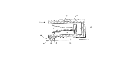
Fig. 1 is a transverse cross-sectional view of the
preferred embodiment;
~ Fig. 2 is a longitudinal cross-section o~ the
preferred embodiment;
Fig. 3 illustrates a detailed partial cross-
sectional view of a safety mounting bolt according to the
preferred embodiment; and


..'


Fig. 4 is a detailed partial cross-sectional view
of the connecting means according to the preferred
embodiment.
Detailed Description of the Preferred Embo~i ~
With reference to Figs. 1 and 2, the horn housing
(10) according to the preferred embodiment comprises an
inner solid shell or box (12) made of stainless steel having
a hexagonal cross-section and an opening at one end. Horns
(14) are mounted inside box (12). An outer dense solid box
(18) is molded from a composite material such as a polymer


2a
:: :


: ., -: :

~ '


resin and a filler. The horns (14) are solidly connected to
inner box (12) by mounting stems (16) which are welded to
box (12). As shown, there may be more than one horn (14)
contained within housing (10). Inner box (12) is connected
to outer box (18) by means of vibration d~ ni ng mounting
bolts (40). The space inbetween inner box (12) and outer
box (18) is filled with a synthetic filter such asl~u~~
foam (20) which acts as a good vibratio~ and sound absorber.
The outer box (18) is connected to a roof (30) of a train by
mounting means (22).
Mounting means (22) comprise a bracket (24)
interconnecting rubber pads (25) and (26) between bracket
(24) and the outer box (18) and roof top (30) respectively.
The vibration dampening mounting bolts (40) are also shown
in Fig. 1 to be positioned on the upper and lower side walls
of the housing such-that the upper bolts (40) lift the inner
shell (12) and the lower mounting bolts (40) push up inner
shell (12). In the preferred emibodiment, there are three
bolts (40) per side one bolt at each end of housing (lo) on
the upper side, and a single bolt in the middle of the side
on thie lower portion.
As particularly illustrated in Fig. 4, the
vibration ~ ,~ni ng mounting bolt (40) according to the
preferred ~ t has a vibration absorbing rubber member
(42) sandwiched between and fastened to an outer bolt (44)
and an inner bolt (46) which fit through holes provided in
outer box (18) and inner box (12) respectively. Nuts (not
shown) may be fastened to the ends of bolts (44) and (46) to
complete the mounting.
With reference to ~ig. 3, a cross-sectional view
of the safety mounting bolt (32) is illustrated which passes
through a sleeve (34) provided in the bottom side wall of
housing (10). Bolt (32) is bo~ded to roof top (30), and nut
(36) is secured to the end of bolt (32) to provide an
additional fastening.
Of course, the rubber pads (25) and (26) can be


r : ~

' 2090806
- ' .


.
replaced by vibration d~ ,?ning bolts (40) in which case,
bracket (24) may be bolted to roof (30) and to outer box
tl8). Preferably, four bolts (40) could be used per
mounting (22).


' ~:


Representative Drawing
A single figure which represents the drawing illustrating the invention.
Administrative Status

For a clearer understanding of the status of the application/patent presented on this page, the site Disclaimer , as well as the definitions for Patent , Administrative Status , Maintenance Fee  and Payment History  should be consulted.

Administrative Status

Title Date
Forecasted Issue Date 1997-12-30
(22) Filed 1993-03-02
Examination Requested 1994-05-27
(41) Open to Public Inspection 1994-09-03
(45) Issued 1997-12-30
Deemed Expired 2008-03-03

Abandonment History

There is no abandonment history.

Payment History

Fee Type Anniversary Year Due Date Amount Paid Paid Date
Application Fee $0.00 1993-03-02
Registration of a document - section 124 $0.00 1993-09-03
Maintenance Fee - Application - New Act 2 1995-03-02 $50.00 1995-02-21
Maintenance Fee - Application - New Act 3 1996-03-04 $50.00 1996-02-26
Maintenance Fee - Application - New Act 4 1997-03-03 $50.00 1997-01-31
Final Fee $300.00 1997-08-11
Maintenance Fee - Patent - New Act 5 1998-03-02 $150.00 1998-02-26
Maintenance Fee - Patent - New Act 6 1999-03-02 $150.00 1999-03-01
Registration of a document - section 124 $100.00 1999-07-12
Maintenance Fee - Patent - New Act 7 2000-03-02 $75.00 2000-03-02
Maintenance Fee - Patent - New Act 8 2001-03-02 $75.00 2001-03-02
Registration of a document - section 124 $100.00 2001-05-25
Maintenance Fee - Patent - New Act 9 2002-03-04 $75.00 2002-02-26
Maintenance Fee - Patent - New Act 10 2003-03-03 $100.00 2003-02-05
Maintenance Fee - Patent - New Act 11 2004-03-02 $125.00 2004-02-24
Registration of a document - section 124 $100.00 2004-12-02
Registration of a document - section 124 $100.00 2004-12-17
Maintenance Fee - Patent - New Act 12 2005-03-02 $125.00 2005-02-28
Maintenance Fee - Patent - New Act 13 2006-03-02 $125.00 2006-03-02
Owners on Record

Note: Records showing the ownership history in alphabetical order.

Current Owners on Record
BAULTAR I.D. INC.
Past Owners on Record
ALBERT, ANDRE
ARCHAMBAULT, BRUNO
BAULTAR ERGO INC.
BAULTAR INC.
MALTAIS, MARIO
Past Owners that do not appear in the "Owners on Record" listing will appear in other documentation within the application.
Documents

To view selected files, please enter reCAPTCHA code :


To view images, click a link in the Document Description column. To download the documents, select one or more checkboxes in the first column and then click the "Download Selected in PDF format (Zip Archive)" or the "Download Selected as Single PDF" button.

List of published and non-published patent-specific documents on the CPD .

If you have any difficulty accessing content, you can call the Client Service Centre at 1-866-997-1936 or send them an e-mail at CIPO Client Service Centre.


Document
Description 
Date
(yyyy-mm-dd) 
Number of pages   Size of Image (KB) 
Representative Drawing 1997-12-16 1 5
Drawings 1997-02-05 2 20
Cover Page 1997-12-16 1 48
Description 1997-02-05 5 108
Abstract 1995-06-10 1 39
Claims 1997-02-05 2 49
Cover Page 1995-06-10 1 59
Claims 1995-06-10 2 102
Drawings 1995-06-10 2 66
Description 1995-06-10 5 232
Fees 2006-03-02 1 30
Correspondence 2000-03-02 1 48
Correspondence 1997-08-11 1 31
Fees 2000-03-02 1 32
Assignment 1999-07-12 6 189
Fees 2003-02-05 1 31
Correspondence 2006-12-28 3 96
Correspondence 2001-07-12 1 25
Fees 2001-03-02 1 34
Fees 2002-02-26 1 31
Fees 1999-03-01 1 36
Assignment 2001-05-25 6 368
Prosecution Correspondence 1993-03-02 10 407
Prosecution Correspondence 1994-05-27 1 37
Office Letter 1994-07-08 1 36
Prosecution Correspondence 1994-05-30 3 91
Prosecution Correspondence 1994-06-30 2 50
Fees 1998-02-26 1 45
Fees 2004-02-24 1 29
Assignment 2004-11-15 1 41
Assignment 2004-12-02 6 176
Assignment 2004-12-17 12 424
Correspondence 2005-02-11 1 16
Fees 2005-02-28 1 29
Assignment 2005-03-22 2 72
Fees 1997-01-31 1 43
Fees 1996-02-26 1 42
Fees 1995-02-21 1 46