Note: Descriptions are shown in the official language in which they were submitted.
- 2090~
This invention relates to hospital beds, and is
particularly concerned with a bed which is convenient and
suitable for home use, but with all the features of a more
conventional hospital bed.
Hospital beds usually have the facility of
elevating the head end of the mattress deck and also the
knee~foot end. Such beds are also usually mobile in that
wheels are provided, with a brake system to prevent
movement of the bed when desired.
Such beds are usually of unitary form and are
therefore at the least very inconvenient for use in a home
as they are difficult to deliver and move into a room.
While it has been proposed to divide a bed into
two parts or members, each part is still fairly bulky, with
a mattress deck part, legs and head or foot board.
The present invention provides a bed which is
composed o~ several parts which can be easily assembled
together to form a rigid bed, and which can be packaged, in
its disassembled form, into a box which is easily
transported. The box is of a size that is readily conveyed
into a house, into any desired roomO Wheels for the bed
can be positioned at particular positions on the packaged
bed, to project through the bottom of the box, for
mobility. These wheels are afterwards repositioned on the
bed for providing mobility of the bed.
The head end and the knee/foot end can be raised
- and lowered, electrically, and the wheels can be raised
rela~ive to the floor, to provide stability and prevent
unwanted movement of the bed.
Broadly a bed in accordance with the present
invention comprises a head section, a foot section and a
seat section, with means ~or connecting the head and foot
sections to the seat section: a set of fixed support legs:
wheels mounted on the bottom ends of the fixed legs; means
for raising and lowering a mattress at said head section
~; ~ : . . : '
~: . ~ ;' ~ :' '' ,', "'. ' " ' : ' ' .; . ,
:-` 2~9~
and said foot section. A head board and a foot board
attached to the opposite ends of the bed. A further set of
legs, extendable and retractable, can be provided, with
means for extending and retracting the legs.
The invention will be readily understood by the
following description of embodiments, by way of example, in
conjunction with the accompanying drawings in whicho
Figure 1 is a perspective view o~ a bed in
accordance with the present in~ention, in a packaged
condition, but without the box;
Figure 2 is a perspective view on the underside
of the head section, as unpacked;
Figure 3 is a perspective view on the underside
of the ~oot section as unpacked;
Figure 4 is a perspective view on the upper side
of the seat section with the head and foot boards, as
unpacked:
Figure 5 is a perspective view similar to that of
Figure 4 showing the seat section separated from the head
20 and foot boards; ;
Figure 6 is a perspective view on the underside
of the head, seat and foot sections, positioned for
assembly; ~:
Figure 6A is a perspective view of a connector
25 bracket for removably securing bed components together; .
Figure 7 is a perspective view on the upper sid~
of the assembled head, seat and foot sections, with seat
board shown: :.
Figure 8 is a perspective view on the underside
of the assembled bed showing the various mechanisms for
raising and lowering the head and foot sections and for
extending and retracting the moveable legs;
Figure 9 is a perspective view on the upper ~ide
of the assembled bed, with head and foot boards attached;
Figure 10 is a diagrammatic side view
~ ~ : :, , , :. .
~ 2 ~
illustrating the head and foot sections raised and the
moveable legs extended;
Figure 11 is a cross section on the longitudinal
axis of the main tube of ~he leg extending and r~tracting
assembly, illustrating the means for removably mounting the
assembly on the ~ed.
Figure 12 is a side elevation of another
embodiment o~ the bed o~ the invention;
Figure 13 is a side elevation of the embodiment
illustrated in Figure 12 showing the head and foot boards
elevated and the legs retracted;
Figure 14 is a perspective view, partly cut away,
of the hinge mechanism of the invention;
Figure 15 is a longitudinal section o~ the hinge
mechanism shown in Figure 14 before assembly;
Figure 16 is a longitudinal section of the hinge
mechanism shown in Figure 15 after partial assPmbly;
Figure 17 is a perspective view of the hinge
mechanism in a fully assembled position;
Figure 18 is a longitudinal section of the hinge
mechanism in its planar position shown in Figure 17:
Figure 19 is a longitudinal section of a panel
assembly showing the said hinge mechanism in an articulated
configuration:
Figure 20 is a plan view of the board assembly of
the bed in a fully planar position
Figure 21 is a side elevation of the board
assembly shown in Figure 20;
Figure 22 is a plan view of the underside of the
board assambly shown in Figure 20; and
Figure 23 is a longitudinal section, partly cut
away, of the board assembly shown in Figure 23.
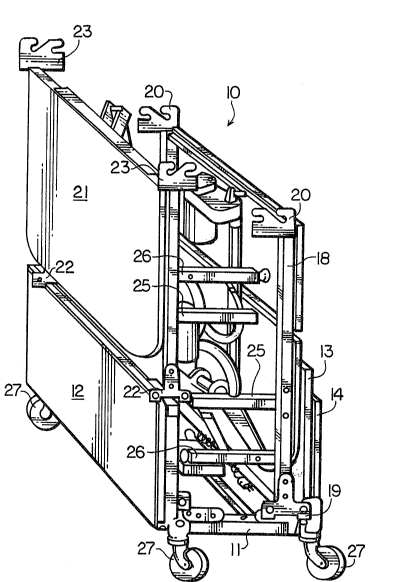
As illustrated in Figure 1, a packed bed,
indicated generally at 10, comprises a seat section 11
having a foot board 12 mounted on one side and a head board
:"" , ,.. ~, ,, :, . .
:^' 2~90~1A
13 mounted on the other side. The foot board and head
board are mounted on the seat section by pairs of brackets
15 and 16, seen more clearly in Figure 4. These brackets,
after the packaged bed is unpacked, are used as connection
means for assembly of the bed. The seat board rests on top
of the other pieces.
A foot section 18 rests, in an upriqht position,
on the seat section, having brackets 19 at one end and
further brackets 20 at the other end. A head section 21
r~sts on the upper edge of the foot board 12, having
brackets 22 at one end and ~urther brackets 23 at the other
end. The head and foot sections carry fixed legs 25 and
movable legs 26. Al~o the various powered mechanisms ~or
raising and lowering the head and foot sections and for
extending and retracting the movable legs are mounted on
the head and foot sections~ being seen more clearly in
Figures 2 and 3.
For ease in moving the packaged bed, wheels 27
are mounted at each corner of the seat support section into
the head and foot board supports 15, the wheels being
removed on unpacking and reused as bed wheels. As
previously stated, the wheels 27 can project through the
bottom of a box in which the bed is packaged.
Figure 2 illustrates the head section 21 removed
from the packaged bed. Gliders 28, or similar members, are
mounted on the lower ends of the movable legs 26 and two of
the wheels 27 are mounted on the fixed legs 25. The ~ixed
legs are mounted on a frame 29. An electric motor 31 is
mounted on the head section frame, driving a linear jack 33
which raises and lowers the head section board, 32 via arms
34, the board pivoting at its inner edge 35. The brackets
22 are mounted at each head end of the head section and the
brackets 23 mounted on each inner end on the frame 29 on
each side.
The moveable legs 26 are mounted on the ~ixed
~ ~ 2 ~
legs 25 by arms 36, each pivotally attached at one end to
a fixed leg and pivotally attached at the other end to a
movable leg. The movable legs 26 are also mounted on the
fixed legs by levers 37. The levers 37 are each pivotally
attached at one end to a movable leg and at the other end
are unitary with and rotatable with a shaft 38 extending
between and rotatably mounted at each end in a fixed leg.
The shaft 38 is rotated by further levers 40, as described
later. The movable legs are interconnected by a shaft or
rod 41.
Figure 3 illustrates the foot section 18 removed
from the packaged bed. Gliders 28, or similar, are mounted
on the lower ends of the movable legs 26, and two vf the
wheels 27 are mounted on the fixed legs 25. The fixed legs
25 are mounted on the frame 42. The movable legs 26 are
mounted on the fixed legs 25 by arms 45 pivotally attached
at one end to a fixed leg and pivotally attached at
the other end to a movable leg. The movable legs 26 are
also mounted on the ~ixed legs by levers 46. The levers 46
are each pivotally attached at one end to a movable leg and
at the other end are unitary with and rotatable with a
shaft 47 extending between and rotatably mounted at each
end in a fixed leg. The brackets 19 are mounted at each
foot end of the foot section and the brackets 20 are
mounted at each inner end, on the frame 42, on each side.
An electric motor 48 is mounted on the foot
section frame and drives one end of a linear jack 49. The
jack 49 is pivotally attached at its other end to levers 50
fixedly mounted on shaft 47. Actuation of the motor and
jack moves the levers 50, rotating shaft 47. This in turn
moves the levers 46 to extend and retract the legs 26~
depending upon the direction of rotation of the motor 48.
Also mounted on the sha~t 47 are further levers 51. These
are connected to the lPvers 40, Figure 2, described later
in conjunction with Figure 8.
2 ~
Also mounted on the foot section frame 42 is an
electric motor 55 driving one end of the linear jack 56
The other end of the jack 56 i5 pivotally attached to arms
57 fixedly mounted on a movably board 58 of the foot
section. Actuation of the motor 55, and jack 56, moves
board 58 and also board 59, boards 58 and 59 being
pivotally connected at their adjacent edges 60 and 61. The
edges 60 and 61 move upward, as illustrated in Figure 10.
Figures 4 and 5 illustrate the seat section 11,
the seat board 14, head 13 and foot 12 boards attachQd in
Figure 4 with the head and foot boards shown detached and
the seat section 1~ turned over ready for assembly in
Figure 5. The seat section comprises a central transverse
frame member 62 and side members 63.
Figure 6 illustrates the seat section 11 and the
head section 21 and foot section 18 in juxtaposition ready
for assembly. To assist in understanding the method of
assembly, the axrangement of the various brackets 15, 16,
19, 20, 22 and 23 will be described, the brackets arranged
to cooperate in pairs. The brackets of the head and foot
boards, brackets 15, are adapted to clip onto the brackets
19 and 20 while the brackets 20 and 23 are intended to clip
on to the brackets 16. Once such pairs of brackets 23 and
16 in engagement is shown enlarged in Figure 6a.
As illustrated in Figures 6 and 6a, a pair of
brackets 23, 16 for assembling sections together, comprises
what can be termed a male bracket-bracket 16, which in the
example is Tee-shaped, the leg 70 being attached, as by
riveting, welding or other means to the outer end of a side
member 63. The cross bar 71 of the bracket extends beyond
the end of the side member and has two pins 72 extending
laterally, relative to the bracket, and spaced vertically,
for example on a vertical axis. What can be termed the
female bracket, bracket 23, is in the form in the example,
of a generally rectangular plate attached to the end o~ the
"': "' ' "'
2090~ A
head section. Bracket 23 extends in a vertical plane, as
does also bracket 16. Two slots 73 extend up lnto the
bracket 23, one ~rom a bottom edge and one in from a free
edge. The inner ends o~ the slots are spaced vertically
for example on a vertical axis, and positioned so as to
receive the pins 72. The head section is assembled to the
seat section by inserting the pins in each bracket 16 at
one edge of the seat section into the slot 73 in each
bracket 23 on the head section. The brackets are pushed
together until the pins are at the ends of the slots. To
retain the brackets in an assembled condition, a clip 75 is
positioned to embrace both brackets of a pair. The clip
(see Fig. 4) is generally U-shaped and has a hole 76 in one
arm to fit over a pin 72. This prevents the pins 72 moving
in the slots 73.
A similar arrangement occurs ~or the bracket 16
and 20 for the assembly of foot section to the seat
section. Once the three sections are assembled via the
brackets 16 and 23 and 16 and 20, with the clips 75 in
position, the assembly is rigid.
Figure 7 illustrates a bed substantially
assembled. The head and foot sections are assembled to the
seat section by the brackets 16 and ~0 and 16 and 23. The
seat board 14 is attached to the seat section by screw 76
passing through the seat board into fitted holes 77 in the
side members 63. Electrical connectors 78, for the motors
31, 48 and 55 can be inserted into the connecting box 64.
A flexible cord 79 is also connected at one end to the
connecting box by a connector 80, with a control box 81 at
the other end o~ the flexible cord 79. A power supply cord
82 has a eonnector 83 for connection to a power supply.
Figure 8 illustrates the assembled bed from
below. The head, foot and seat sections are interconnected
and a tube or other connecting member 90 is pivotally
connected at each end to the levers 40 and lever~ 51. ~y
f ' ' ' ' " " " ~ ~ ' ' ' ' i ' ' ' ' . '
': ', : ' , '~ ", j , ' ,, : ' ',
r~ 2 ~ 9 0 ~ ~ ~
this means, when shaft 47 is rotated by motor 48, jack 49
and levers 50, sha~t 38 is also rotated. Rotation of the
sha~ts 47 and 38 raises or lowers the movable legs 26,
depending upon the direction of rotation of the motor 48.
Also seen in Figure 8 are the bars 91 which provide
stability for the fixed legs 25.
Figure 9 illustrates the assembled bed, from
above, and also shows the head board 13 and foot board 12
in position. The head board is attached via the brackets
15, and brackets 19 and 22 respectively on the foot section
and head section. The connection of the brackets is in the
same manner as for the bed sections, pins 72 on the
brackets 22 (Fig. 6a) fitting in slots 73 in the brackets
15. Clips of the same form as clips 7i5 can be used to
prevent unwanted removal of the head and foot boards. Alio
shown in Figure 9 are rails 97, in the example being formed
square tubes welded to the frame members 29 and 42.
In Figure 10 the head section board 33 is shown
in a raised position and the foot section boards 58 and 59
are also shown in a raised position. It will be
appreciated that only th~ head section board, or the foot
section boards need be raised as desired. In Figure 10 the
movable legs 26 are shown in an extended position. This
raises the bed with the wheels 27 off of thei floor. This
immobilizes the bedO The legs 26 can be retracted to bring
the wheels 27 in contact with the ~loor if it is desired to
move the bed.
Figure 11 illustrates a removable mounting
arrangement for the movable legs 26, shaft 47, motor 48,
jack 49 and lever~ 50 and 51 from the foot section. The
shaft 47 is rotatably mounted at each end in support
members 100 on the fixed legs 25. At one end a pin 101
which is fixed in the end 102 o~ the shaft 47, is mounted
in one of the support members 100. Ak the other end a
spring loaded retractable pin 103 is pro~ided, slida~le
,,~ .. , . , ." ,,. ,.,, " . , ,., , . . - ", , .-, - .. -., - .. . . . ..... ..
j;, ,, , ' , ', .
2 ~ ~ 0 9 A~ ~
axially in the shaft 47, urged outwards by the spring 104.
The pin 103 inserts into the other support member 100.
Access to the end of the pin 103 is provided by the holes
105 in the fixed leg. The shaft and associated structure
is assembled to the front section by first inserting pin
101 in its support member. Pin 103 is pushed in and the
shaft end inserted at the other support member, and
positioned so that the pin 103 moves into the other support
member. The motor 48 is pivotally attached to the ~ront
section by a pin joined between a bracket 106 on the bed
section and linear jack 49 on the motor 48 (Figure 3). The
arms 45 are also readily disengagable from the legs 25.
A similar mounting arrangement can be provided
for the shaft 38, levers 37 and legs 26 on the head
section. Thus, if desired, a bed can be supplied without
the provision of movable legs and associated operating
mechanism. This can be added later if desired.
The bed of the present invention provides various
advantages. The motors are mounted adjacent to the
particular member which is to be moved, eliminating drive
members between the jack and the driven member or element.
The wheels can be mounted in two different
positions, alternately for mobility in the packaged
condition and for assembled bed mobility.
The bed breaks down into a number of basic
pieces, for example five, for ease of storage and more
compact packaging. These pieces, in the example described,
are head board, head section, seat section, knee/foot
section and foot board. No piece is very large or heavy
which allows easy carrying upstair~ to a bedroom.
The movable legs which move down, do not carry
the wheels. Thus the bed is immobilized by moving the
movable legs down, thus lifting the bed and also lifting
the fixed legs, and wheels, up. This is different from
~ ~ 2 ~
11 .
previous beds where the movable legs carry wheels and are
moved up to bring the fixed legs into conta~t with the -
floor. This immobilizes the bed in a lowered position,
while with the bed of the present invention, the bed is
immobilized in the up position, usually more convenient,
especially for care personnel. Removable head and foot
boards as illustrated in the drawings are necessary for the
function of the said bed and therefore interchangeable with
other boards of the owner's preference.
10The bed is readily converted to one which does
not have the elevating features, the raising and lowering
mechanisms being easily removable and snapping into
position i~ required. ~ ~-
The mattress deck, in the prasent example, that -
is head, foot and seat boards 14, 32, 58 and 59, are
panels, having a wood core encapsulated in a fire rated
synthetic resin. The resin surface can be texturized to
help prevent the mattxess from slipping. Wood core
provides a stiffness while the encapsulation prevents
moisture and bacteria absorption. As they are non-ferrous,
the panels will not rust if scratched or otherwise damaged.
Also, with metal panels, condensation can occur between
mattress and panels. The present panels avoid this. In
many conventional beds the mattress deck is metal framed
with link fabric. This can tear the bedding or mattress
and is in its complexity difficult to keep clean. -
Various other differences occur. In the bed of
the present invention, tubular structures and frames are
used, as against angle cross-sections. This is lighter and
is also easier to keep clean.
Figures 12 and 13 illustrate another embodiment
of the bed of the invention in fully assembled positions.
Figure 12 illustrates the bed 110 having both pair of legs
126 extended by retraction of rod 190 to the right, as
viewed in Figure 12, in the manner described with referencs
.V . ' , , . ~,, ,,,, ~ . ,. , , . ~ . .
2 ~
12
to rod 90 shown in Figure 8.
Figure 13 illustrates upward retraction of both
pairs of legs 126 and fur~her illustrates upward pivvtal
movement of panel 132 of the upper body section and
artiriulation of panels 158, 159 of the foot section.
Actuation of motor 155 and linear drive 156 pivots bell
crank 157 to pivot panel 159 and raise panel 158
articulated thereto, as will be described. Actuation of
motor 131 and linear dri~e 133 pivots bell crank 134 to
pivot panel 132 upwardly about joint 135 at the juncture
with seat panel 136.
With re~erence now to Figures 14-23, Figures 20-
23 illustrate the panels in their flat-lying position, each
panel having a plurality of spaced-apart circular spacers
139 ~ormed on the underside thereof at longitudinal
reinforcing ribs 140 which form a reinforcing lattice with
transverse reinforcing ribs 141. A down-turned shallow
- edge ~lange 152 is formed along the longitudinal edges of
the panels and along the transverse edges thereof for
reinforcement, the panels normally being ~ormed from a
rigid plastic such as by injection molding.
Figures 14-19 illustrate in detail hinge joint
135 which will now be described to typify the articulated
joints of the invention. Each panel, eOg panel 136, has
at one end a transverse, generally cylindrical bar 145
spaced from transverse flange 142 and secured thereto by
equispaced panel extension 146 defining narrow slots 147
: therebetween. Bar 145 has a flat face 143 parallel to
transverse flange 142 at slots 147 and has a diametrically
opposed flat face 144 along the opposite side of bar 145.
The opposite end of each panel, e.g. panel 132,
has a plurality of equispaced, arcuate extensions 148, 149
alternating from opposite sides of the panel edge flange
142 adapted to mate with and fit into slots 147 when
adjacent panels are positioned perpendicular to each other
~ 21~9091~
as indicated more clearly in Figure 15. Adjacent
extensions 148, 149 are effectively opposed to each other
and define a cylindrical recess 151 having a diameter
substantially equal to the full diameter of transverse bar
145. The distal ends 152, 153 of extensions 1i~8, 149
respectively are truncated to provide a gap width 154
(Figure 19) substantially equal to the width 155 o~ bar 145
(Figure 15) to allow opposed extensions 148, 149 to snugly
fit over bar 145 when adjacent panels are fitted
perpendicular to each other, as shown in Figure 16.
Upon pivoting of one panel relative to another
from a perpendicular position to an angle of l~ss than 909,
the effective width of the bar 145 becomes the full
diameter thereof, which is larger than the gap width 154
between the distal ends 148, 149 to lock the panels
together as depicted in Figures 17-19, Figures 17 and 18
showing adjacent panels in a flat-lying position and seated
on a supporting surface. Figure 19 shows three connected
panels corresponding to panel~ 136, 159 and 158 articulated
essentially into the position shown in Figure 13.
It will be understood that the hinge connection
has utility for detachably joining panels together to ~orm
partition walls, shutters, curtains and doors. Overhead
garage doors, for example, which can be opened and closed
by motorized systems, can be readily assembled from a
plurality of elongated panels incorporating the hinge
system of the invention. Light-weight partition walls can
be quickly and easily assembled into a variety of
confi~urations.
The bed, in khe packaged condition, is very
compact and easily moved about. The packaged bed can be
moved in the packaged condition, in a container, with the
wheels projecting at the bottom. If it is desired, or
necessary, to move the bed in sections, ~or weight or space
reasons, it can be broken down into the separate sections
~ ;.~.' ~ . , , . ' !, ,, ' , . i . '
` ~ ~ 2 ~
14
and very quickly reassembled.
It will be understood, of course, that
modifications can be made in the embodiment of the
invention illustrated and described herein without
departing ~rom the scope and purview of the invention as
defined by the appended claims.