Note: Descriptions are shown in the official language in which they were submitted.
1
II~~~~I) ~~h~~, F~I~ ~ ITC,°1'I4t'~
IDF FI~LTIC~.1~~T~ lI~TTEI3,
C:E~GII,OO~ TIC I1~T~~TT'i~1~T
r . held a~f tip Inveaati~a~
1 0 This invention relates to a stopper for a container and, more
particularly, to an improved stopper for a container of parentexal
solutions which is suitable for infusion spike penetration without
producing unacceptable .amounts of particulate matter.
2. Reported I~velopmea~
Stopper systems for vials, bottles and the like are made of
materials that are resistant to chemicals and pharmaceuticals such as
2 Q corrosive materials, reagents, parenteral solutions and solid
formulations reconstitutable with a solvent prior to use. The most
commonly used stopper system for such products has been glass or
plastic bottles and vials eguipped with rubber stoppers made of
elastomeric materials. The system appears to provide for good
2 5 hermetical seal, safe stoxage and easy access to the content through the
elastomeric stopper via the use of an infusion spike when withdrawal of
the content is desired. The elastomeric stopper used comprises an
elastomeric base; such as natural or synthetic rubber and an inert
coating covering at least some portions of the stopper. The coating used
3 0 heretofor includes chlorobutyl rubber, polymeric fluorocarbon resins
such as polytetrafluoroethylene (TEFLON) and various thermoplastic
films. The coating is intended to insulate the elastomeric stopper base
from the content of the container in order to prevent contact and possible
chemical reactions therebetween.
One of the major concerns in all products, and especially
pharmaceutical parenteral products, is the generation of particulate
*Trade-mark
~~~.~~0
2
foreign matter which may contaminate such products. In order to
eliminate macroscopic and microscopic particulates, elaborate
measures have been taken to remove them, such as filtration of the
product and special washing and drying of the stopper system
components. These steps help assure that the products meet the
requirements and guidelines of the pharmaceutical industry, such as
compendia guidelines, when the products reach the point of use.
However, at the point of use, such as in the case of a parenteral product,
new particulate matter is frequently generated by the practitioner when
1 0 the stopper is penetrated by a needle or spike of an infusion set ox an
infusion spike. During such penetration a combination of elastic and
plastic deformation of the stopper target area increases the stopper
contact surface with the infusion spike as it is pressed into the stopper.
Typically, untreated elastomeric stoppers offer a high degree of
1 5 resistance against the exterior surface of the spike as the spike is being
pushed into the penetration area. Most frequently, when stopper
fragments axe generated, they are the result of the elastomeric por tion of
the stopper being abraded off the upper surface of the stopper as it
conforms to the shape of,the penetrating spike. The fragments are then
2 0 transported into the interior of the vial as the spike rolls and drags the
fragments during penetration.
In addition to the problem of particulate matter produced and
carried into the vial during the spiking procedure, there are two other,
2 5 although less frequently occurring, anomalies: stopper push-through
into the vial and spike blow-out caused by residual elastic tension of the
stopper against the spike which urges the spike outward.
The most common solution to these problems has been the
3 0 application of silicone lubricant to the stopper and/or the spike to
reduce
the frictional drag between the stopper and the spike. While silicone
does reduce particle generation from the spiking procedure, it also
increases the risk of product contamination from its own composition.
Another approach proposed in the prior art to reduce the tendency
of the stopper to generate particulate matter during manufacturing and
storage is to coat the elastomeric core of the stopper with a thermoplastic
film on the fluid contacting side thereof. We have found, however, that
the use of such construction is less than satisfactory to solve the
problem.
The present invention addresses the need to eliminate or at least
greatly reduce the particle generation from surface erosion of the
1 0 stopper during spike penetration. In addition, the invention reduces the
risk of the push-through and blow-out tendency by minimizing frictional
drag and residual elastic tension during spike penetration. These
advantages are achieved without the use of a lubricant, such as silicone
oil, which could contaminate the product contained in the vial or bottle.
1~
CA 02091020 2004-O1-19
20208-1567
4
SU1~ARY OF THE INVENTION
We have surprisingly found that if a non-reactive,
inert, abrasion resistant coating is applied to the upper
surface of an elastomeric stopper where spike penetration
will take place, particle generation during spiking is all
but eliminated and the tendency of push-through as well as
blow-out of the spike is greatly reduced.
Accordingly, in its broadest aspect, this
invention provides a stopper for medical vials which is
highly resistant to abrasion and formation of particulate
materials upon spike penetration, comprising:
a stopper body of an elastomeric material having a
cylindrical shape and top surface; and
an abrasion resistant coating to prevent
generation of particles upon spike penetration of the
stopper when withdrawal of fluid is desired.
In use, the coating on the top surface of the
stopper conforms to the deformation of the stopper caused by
the spike penetration procedure. It appears that, upon
piercing, the spike is not in contact with the elastomeric
stopper body but only with the abrasion resistant coating
thereby circumventing abrasion and eliminating the formation
of elastomeric particulate materials.
One preferred embodiment of the invention provides
an abrasion resistant stopper for a medical vial containing
a fluid therein, which stopper is to be pierced by an
infusion spike and comprises a stopper body of an
elastomeric material having a head portion and a fluid
contacting leg portion, where the leg portion is to be
inserted into the medical vial to hermetically seal the
CA 02091020 2004-O1-19
20208-1567
4a
fluid therein, the head portion having a fluid-contacting
bottom surface and a top surface having a central pierceable
portion, the central portion having a spike-receiving
surface, wherein:
the spike-receiving surface is coated with an
abrasion resistant film which conforms to edges of a hole
created by an infusion spike upon the spike piercing the
stopper and provides a barrier between the spike and
elastomeric material, thereby preventing mechanical contact
between the spike and the elastomeric material and
consequent generation of elastomeric particles by abrasion;
and
the abrasion-resistant film is made of a material
selected from the group consisting of polystyrene, polyvinyl
acetate, polyvinyl chloride, polyvinylidene chloride,
copolymer of vinyl chloride and vinylidine chloride,
polymethylene oxide, polyphenylene oxide, polyphenylene
sulfone, polyethylene terphthalate, polycarbonate,
copolyesters and polycaprolactam.
Another preferred embodiment of the invention
provides an abrasion resistant stopper for a medical vial
containing a fluid therein, which stopper is to be pierced
by an infusion spike and comprises:
a stopper body of an elastomeric material having a
head portion and a fluid contacting leg portion, wherein the
leg portion is to be inserted into the medical vial to
hermetically seal the fluid therein, and the head portion
comprises a fluid-contacting bottom surface and a top
surface having a central spike pierceable portion; and
CA 02091020 2004-O1-19
20208-1567
4b
an abrasion resistant film coated on the central
pierceable portion of the top surface of the head portion,
wherein:
the abrasion resistant film conforms to edges of a
hole created by deformation of the stopper body;
the spike gets in contact with only the abrasion
resistant film to prevent generation of particles of the
elastomeric material upon piercing of the stopper by the
spike; and
the abrasion resistant film is made of a material
selected from the group consisting of polystyrene, polyvinyl
acetate, polyvinyl chloride, polyvinylidene chloride, co-
polymer of vinyl chloride and vinylidene chloride, polyvinyl
fluoride, polyvinylidene fluoride,
polychlorotrifluoroethylene, polytetrafluoroethylene,
polymethylene oxide, polyphenylene oxide, polyphenylene
sulphone, polyethylene terephthalate, polycarbonate,
copolyesters, polycaprolactam, polyhexamethylene adipamide
(nylon 66) and polyundecanoamide.
Still another preferred embodiment of the
invention provides an abrasion resistant stopper for a
medical vial containing a fluid therein, which stopper is to
be pierced by an infusion spike and comprising:
[A] a stopper body of an elastomeric material
having a head portion and a fluid contacting leg portion,
wherein:
the elastomeric material is a fluid impervious,
resilient and inert material free of additives leachable to
the fluid;
CA 02091020 2004-O1-19
20208-1567
4c
the head portion comprises a top surface and a
circular flange to cover a corresponding planar circular
mouth portion of the medical vial; and
the leg portion is to be inserted into the medical
vial to hermetically seal the fluid therein and has a recess
extending from its bottom upward toward the top surface of
the head portion such that a thin central pierceable portion
is formed in the head portion, and
[B] an abrasion resistant film having a thickness
of 0.02 to 0.5 mm coated on the top surface of the head
portion, wherein:
the abrasion resistant coating covers the thin
central pierceable portion of the head portion;
when piercing the thin central pierceable portion
of the head portion by the infusion spike, the abrasion
resistant film conforms to a deformation of the stopper body
and the spike is in contact only with the abrasion resistant
coating, thereby preventing generation of particles from the
elastomeric stopper body;
the abrasion resistant film is made of a material
selected from the group consisting of polystyrene, polyvinyl
acetate, polyvinyl chloride, polyvinylidene chloride, co-
polymer of vinyl chloride and vinylidene chloride, polyvinyl
fluoride, polyvinylidene fluoride, polychlorotrifluoroethylene,
polytetrafluoroethylene, polymethylene oxide, polyphenylene
oxide, polyphenylene sulphone, polyethylene terephthalate,
polycarbonate, copolyesters, polycaprolactam, polyhexamethylene
adipamide (nylon 66) and polyundecanoamide.
5
TF~' Fsr-i ~F . DRA'(''_.~
10
FIG. 1 is a perspective view of one embodiment of the stopper of
the present invention;
FIG. 2 is a plan view of the stopper shown in FIG. 1;
FIG. 3 is a cross sectional view of the stopper shown in FIG. 2
taken along the line a - a;
FIG. 4 is a perspective view of another embodiment of the stopper
of the present invention;
FIG. 5 is a plan view of the stopper shown in FIG.4;
FIG. 6 is a cross sectional view of the stopper shown in FIG. 2
taken along the line b - b; and
FIG. ? is a cross section of a vial containing an injectable liquid
2 0 closed with the stopper of the present invention.
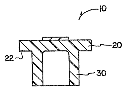
2 5 Referring to FIGS: 1, 2 and 3, numeral 10 shows one embodiment
of the stopper of the present invention comprising: a head portion 20 and
a leg portion 30. Head portion 20 comprises a flmge 22 which is adapted
to cover a corresponding planar, circular mouth portion of a medical
vial, while leg portion 30 is adapted for insertion into the neck of the vial
3 0 to tightly seal the content therein. Numeral ~0 shows an abrasion
resistant hlm mounted on the center part of the head portion 20 which
serves as the piercing area for insertion and withdrawal of a spike or
hypodermic needle.
3 5 Referring to FIGS. 4, 5 and 6, numeral 10' shows another
embodiment of the stopper of the present invention comprising: a head
portion 20' and a leg portion 30'. Head portion 20' comprises a flange 22'
which is adapted to cover a corresponding planar, circular mouth
portion of a medical vial, while leg portion 30' is adapted for insertion
6 26299-46
into the neck of the vial to tightly seal the content therein. Numeral 40'
shows an abrasion resistant film mounted on the top part of the head
portion 20'. In this embodiment recess 32' extends toward the top
surface of the head portion 20' forming a thin portion 34' in head portion
20' for facilitating piercing of the stopper by a spike.
FIG. ? illustrates a stopper 10 having an abrasion resistant film
40 covering vial 1. Vial 1 containing an injectable fluid 5 is sealed by
stopper (10 or 10') by inserting leg portion 30 of the stopper into the neck 7
1 0 of the vial 1. Flange portion 22 of head portion 20 tightly seals the
mouth
~ of vial 1. A thin metal foil 9 is crimped over head portion 20 and flange
portion 22 of stopper (10 or 10') to tightly seal and securely hold the
stopper in vial 1.
14!Iatgrials c~f Cuxiataraxcta~n
The elastomeric material of the stopper body must be a fluid
impervious, resilient, and inert material without teachable additives
2. 0 therein in order to prevent any alteration of the product contained in
the
vial. It rnay be of a single component or a blend of components.
Examples of materials include synthetic or natural rubber, such as
butyl rubber, isoprene rubber, butadiene rubber, silicone rubber,
halogenated rubber, ethylene propylene therpolymer and the like.
2 S Specific examples of a synthetic elastomeric rubber include the CT32CF2-
C~Fs(CgF5I3) and the C2F4-C~F~OCF3 series of elastomers made by
duPont under the trade marks VITON~' and CARLEZ~'; the fluoro-
silicone rubbers, such as those made by Dow Corning under the ~'ademark
SILASTIC~' ~ and polyisobutylenes, such as VTSTANEX'~ MML-100 and
3 0 MML-140; and halogenated butyl rubber, such as CI-TLOROBUTYI~*108F,
made by Exxon Chemical Company.
These or other suitable elastomers may be made into the desired
stopper configuration by known methods. Such methods conventionally
*Trac~e-mark
CA 02091020 2004-O1-19
20208-1567
7
include the use of a curing agent, a stabilizer and a filler
and comprise a primary and secondary curing step at elevated
temperatures.
The abrasion resistant coating for covering the
top portion of the stopper, but at least the center,
pierceable portion thereof, may be: a polyolefin, such
polypropylene and polymethylpentene; a polyvinyl, such as
polystyrene, polyvinyl acetate (PVA), polyvinyl chloride
(PVC), polyvinylidene chloride (PVDC), a copolymer of vinyl
chloride and vinylidene chloride, polyvinyl fluoride,
polyvinylidene fluoride, polychlorotrifluoroethylene and
polytetrafluoroethylene (TEFLON); an ether, such as
polymethylene oxide, polyphenylene oxide and polyphenylene
sulphone; an ester, such as polyethylene terephthalate
(PET), polycarbonate and copolyesters; an amide, such as
polycaprolactam (Nylon 6), polyhexamethylene adipamide
(Nylon 66) and polyundecanoamide (Nylon 11). In certain
embodiments, the top portion of the stopper has a region
which surrounds the center pierceable portion and is not
coated.
The abrasion resistant coating covering at least
the center, pierceable portion of the top surface of the
stopper is preferably polytetrafluoroethylene sold under the
trade mark TEFLON by duPont. The coating thickness will be
in the range of about 0.002 to 1.0 mm, and preferably about
0.02 to 0.5 mm. The coating may be applied or bonded to the
stopper body in any suitable manner known in the art, such
as, but not limited to, by the use of adhesives, solvents,
spray applications, radio waves, infrared, microwaves,
ultrasonics and heat.
The stopper of the present invention comprising an
elastomeric material and a TEFLON coating on the top center
CA 02091020 2004-O1-19
20208-1567
7a
portion thereof was tested against another stopper of the
same elastomeric material but without the TEFLON coating
thereon.
The vials were capped with the stoppers. Each
stopper was pierced with a spike and then the spike was
removed. The vials were examined for the presence of
elastomeric particles caused by the piercing. The result of
the spiking is shown in Table 1.
l~Ieau
i~ln. ~f ~ P' °ch
Present Invention 25 . 0.6
Elastomeric (Control) 25 15.4
i 0 The present invention has been described in connection with the
preferred embodiments shown in the drawings, it is to be noted,
however, that various changes and modifications are apparent to those
skilled in the art.
i5