Note: Descriptions are shown in the official language in which they were submitted.
23l~ l
-- 1 --
MINIATURE ZINC-AIR CELL }lAVING
AN IN~IUM PLATED ~NODE CUP
Field of the Invention
The invention relates to a miniature zinc-
air cell using an indium coated anode cup in which ~
the indium layer of the anode cup contacts the zinc -
electrode of the cell and wherein the mercury
normally employed in the zinc electrode is reduced to
as low as zero percent.
Backqrouad of the Invention
Alkaline electrochemical cells employing a
zinc anode have become commercially important as a
relatively high rate source of electrical energy.
The alkaline electrolyte, which is usually
lS concentrated aqueous potassium hydro~ide, is a ; -
principal factor contributing to the ability of these
cells to deliver high rates of electrical energy
compared to the older Leclanche cells which utilize
zinc chloride and/or ammonium chloride electrolytes.
However, as is so often the case with technological
advances, the presence of alkali in an electrochemical
cell is a mixed blessing. For instance, alkali
strongly promotes the reaction of water with zinc ca~sing
corrosion. Unless means are employed to control this
reaction, the shelf life of alkaline zinc cells ~ould
be unacceptably short. In addition, since hydrogen
gas is released in the reaction between alkali and
zinc, there may be a danger of cell disassembly.
In commercial alkaline zinc cells, the
reaction between zinc and alkali has been controlled
or reduced to an acceptable rate by the addition of
39
(
-- 2 --
mercury to the cell. Unfortunately, it has recently
become apparent that the introduction of mercury into
the environment may be a hazard to human health as
well as to other forms of life. While individual
cells contain only a small amount of mercury, the
very large number of zinc alkaline cells marketed
today could cause significant quantities of mercury
to enter the environment upon disposal of such cells.
U.S. Patent 3,847,699 disclosed an alkaline
zinc-manganese dio~ide cell in which the proportion
of mercury needed to achieve acceptable storage life
can be reduced by the addition of small amounts of an
ethylene oxide polymer.
U.S. Patent 4,500,614 discloses an alkaline
lS cell having an anode prepared by amalgamating an
alloy powder made of zinc and at least two metals
selected from the group consisting of gallium, indium
and thallium. The metals are incorporated in the
cell to reduce the amount of mercury reguired to
prevent corrosion of the zinc in an alkaline
electrolyte which causes generation of hydrogen
gas and subsequent leakage of the electrolyte.
German Patent 1,086,309 discloses an
alkaline zinc cell in which an indium compound is
added to the electrolyte and/or indium metal is
alloyed with refined zinc so as to protect the zinc
against corrosion in an acidic, neutral or alkaline
electrolyte.
Japanese Publication No. 1958-3204,
published April 26, 1958, recites that the addition
of 0.0001% to 2.0% indium can be added to pure zinc
base alloy containing one, two, or more of the
.~ , , . . . ., . :
: . . -, . :, . ~
,
s~ 9
-- 3
metallic elements Fe, Cd, Cr, Pb, Ca, Hg, si, Sb, Al,
Ag, Mg, Si, Ni, Mn, etc., to form a zinc alloy which
has a high corrosion resistance and which is suitable
for use in primary cells.
Japanese unexamined patent application
01-307161 is directed to a mercury-free alkaline cell
wherein the negative electrode's collector is coated
with indium and/or lead in which the coating can be
supplied by any method such as electroplating.
As seen from the above, manufacturers of
alkaline batteries have invested substantial amounts
of time and mone~ in the effort to develop
mercury-free batteries. The first batteries to
incorporate mercury-free constructions were the AA, C
and D standard alkaline batteries. These batteries
have historically used the largest quantities of
mercury per cell and are the most common sizes and
type purchased by consumers. Therefore, removinq
mercury from these batteries was the best way to
significantly reduce the quantity of mercury that is
currently entering the general waste stream when used
alkaline cells are thrown away.
In addition to developing mercury-free
standard alkaline batteries, battery manufacturers
have also sought to develop miniature zinc-air
battery constructions that are free of mercury.
While a layman may believe that the technology used
to produce mercury-free standard alkaline batteries
can be used to produce mercury-free miniature zinc-
air batteries, the manufacturers of miniature zinc-
air batteries have found that additional technology
had to be developed before mercury-free miniature
,
2 3 9
(
zinc-air cells could be manufactured on a commercial
basis. The construction of a miniature zinc-air
battery is substantially different from the
construction of a standard alkaline ba.ttery. These
differences in construction have forced battery
manufacturers to develop processes and techniques
that pertain only to the miniature zinc-air cells.
It is an object of the present invention to
provide a miniature zinc-air cell which has a reduced
amount of mercury of less than 6%, preferably less
than 3~, in the zinc-containing electrode and most
preferably having a mercury-free zinc-containing
electrode.
It is another object of the present '
invention to provide a miniature zinc-air cell with a
zinc-containing electrode that is substantially free
or completely free of mercury and wherein the surface
of the electrode cup contacting the zinc-containing
electrode has an undercoat of copper and a top coat
of indium.
It is another object of the present
invention to provide a method for producing an indium
coated cup for housing a zinc-containing electrode of
a miniature zinc-air cell.
These and other objects of the invention
will be apparent from the following description.
~arY of the Invention
The invention relates to a zinc-air cell
employing a manganese dioxide-containing electrode
(cathode) and a zinc-containing electrode (anode)
assembled within a conductive housing comprising a
., ~
. ~ - .: . . : . :
. . : : -
. .
6 ~ 3 ~
cathode cup having at least one opening to permit air
to enter and said cathode cup being electrically
contacted to the manganese dioxide-containing
electrode; an anode cup electrically and physically
contacted to the zinc-containing electrode; said
cathode cup secured to and insulated from the anode
cup; and said anode cup comprising a conductive
substrate having on a portion of at least the inner
surface contacted to the zinc-containing electrode an
underlayer of copper and a top layer of indium.
As used herein, the underlayer of copper
could be pure c~pper or a copper alloy, preferably an
alloy not containing an element that would be
replaced by indium, and the top layer of indium could
be pure indium or an indium alloy. The top layer of
indium could be a continuous layer of indium for most
cell applications operating at ambient temperature
(20C~. However, in some applications, such as high
temperature environments, it may be preferred to have
a discontinuous layer of indium in which some of the
copper underlayer is exposed to contact the
zinc-containing electrode. Preferably in cells for
high temperature application, the indium layer could
cover less than 95% of the surface area of the anode
cup that contacts the zinc-containing electrode.
This will e~pose a portion of the copper undercoat to
contact the zinc-containing electrode. Thus,
depending on the application for the zinc-air cell,
the indium layer could be continuous or
discontinuous. For most applications, the copper
layer should be at least 1 microinch thick,
preferably above 100 microinches thick, and most
. ., , ; . , ~ , . ~ .
~ 2 3~ ,
preferably from 1000 to 2000 microinches thick. The
indium laye~ should be from 0.5 to 50 microinches
thick, preferably from 1 to 5 microinches thick, and
most preferably from 1 to 3 microinches thick. If
the thickness of the indium layer e~ceeds 30
microinches the cost of the indium becomes
e~ceedingly high while contributing no additional
benefit. On the other hand if the thickness of the
indium layer is less than 0.5 microinch then in most
applications the amount would be insufficient to
effectually eliminate mercury from the
zinc-containing e~lectrode without affecting the
cell's characteristics. The substrate of the anode
cup is preferably steel with a layer of nickel on one
surface and a layer of copper on the other surface.
The nickel plated layer is disposed on the outer
surface of the cup and is used as one terminal for
the cell. The copper plated layer is disposed on the
inner surface of the cup over which a layer of indium
is deposited. Thus the indium coating forms the
inner layer of the cup and contacts the
zinc-containing electrode. The conductive substrate
could also be made of cold rolled steel, brass, and
any other suitable metal.
The invention also is directed to a method
for producing an anode cup for a zinc-air cell which
comprises the steps:
(a) depositing on one side of a conductive
sheet a layer of copper and then electrodepositing
onto said copper layer a coating of indium; and
(b) forming the coated sheet into a cup
shaped configuration defining a cavity in which the
. . .
~' .': '.; ~ ' .`
' ' ' '; ,' , , ',": ' ' ', ' : :' :
" ., ~ ' " . ' ~ '~' ' "'
~f~
indium layer forms the inner surface defining the
cavity.
The anode cup could then be filled with a
zinc-containing electrode and assembled with a
cathode cup having at least one opening for
: permitting air to enter the cup and containing a
manganese dioxide-containing electrode in which said
anode cup is secured to and electrically insulated
from the cathode cup using an insulative gasket.
Electroplating indium onto the copper
surface of a laminated strip stock which is used to
form miniature cell anode cups offers several
advantages relative to other methods of depositing
indium onto the surface of an alkaline cell~s current
collector. First, electrodepositing the indium onto
strip stock means that the uniformity of the indium
' plating can be accurately controlled. This is
~, particularly important since the configuration of the
anode cup would effectively prevent the uniform
deposition of indium onto the surface of a formed
-, anode cup. Second, electroplating onto strip stock
enables the manufacturer to accurately control the
location of the plated indium. If formed cups were
plated in a barrel plating operation, the indium
would be plated also on the nickel surface as well as
the copper surface. Selectively controlling the
plating of indium onto only the copper surface is
important to battery manufacturers because the indium
must not be allowed to contaminate the nickel plated
surface of the anode cup. Third, the preferred
thickness of indium, which ranges from 1 microinch to
appro~imately 5 microinches, can be readily obtained
. . .". , , . ' ,' . . "' '' ' ' .'.''. ~ ' ' " ' ' ' `
S , i, , . ' '. ~ ;`. .:
(`` ,~
using an electrodeposition process. These quantities
of indium generally cannot be attained by other
conventional plating techniques, such as, relying
upon indium ions in the electrolyte to.plate onto the
anode cup's surface. Fourth, in specific
applications where a noncontinuous layer of indium is
preferred, portions of the copper surface should be
made to directly contact the anode material so that
the cell's impedance does not increase e~cessively
when the cells are stored at high temperature. Since
the quantity of indium deposited onto the copper
surface can be a~curately controlled, the
discontinuous character of the indium layer can be
assured. Fifth, another advantage of the proposed
invention is that the electrodeposition technique of
this invention will work when chemical displacement
of indium ions cannot be used. The chemical
displacement process relies upon the presence of zinc
or some other reducin~ component in a collector. The
copper surface of a miniature zinc-air cell's anode
cup does not contain zinc which the indium can
replace. Therefore, the chemical displacement
process cannot be used with a miniature anode cup
whose inner layer is copper.
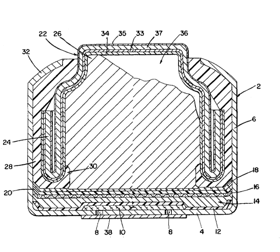
~ e~ riptlQn~of the Drawin~
The sole figure shows the cross-sectional
view of a miniature zinc-air cell employing an anode
cup in accordance with this invention.
Detailed Description of the Drawinq
As shown in the drawing, the largest
component of the zinc-air cell is an open ended ~etal
- . , ~..,, .. . . ,i .: .~.
: . ,~ . ., . - .
3 ~
container 2 identified as a cathode cup. The cathode
cup 2 is generally made from nickel plated steel that
has been formed such that it has a relatively flat
central region 4 which is continuous with and
surrounded by an upstanding wall 6 of uniform
height. Two small holes 8 are punched into the
bottom 4 of the cup 2 to act as air-entry ports. A
layer of porous material 10 covers the interior
surface of the air holes and acts as an air
distribution membrane. A layer of
polytetrafluoroethylene 12 covers the entire bottom
of thé cathode c~p 2 including the air distribution
membrane 10. The second major component is an air
electrode 14 which is positioned adjacent the inside
surface of the polytetrafluoroethylene layer 12.
This electrode 14 contains several components,
including: a metal screen 16; a mixture of manganese
oxides and carbon embedded in the screen 16; a
barrier ~ilm 18 which prevents the anode's
electrolyte from moving into the cathode 14; and a
soakup separator 20. The third component is a
generally cup-shaped metal component 22 which forms
the top of the cell and is generally referred to as
the anode cup. In the figure, the edge 24 of the
anode cup has been rolled backward upon itsel~
thereby creating a double wall. The anode cup 22 can
be made from a trilaminate material comprising copper
33 that has been laminated to the bare side of a
nickel-clad steel strip. A nicke] layer 35 protects
the exterior surface of steel strip 37 which is located
between nickel layer 35 and cooper layer 33. Other
laminated materials from which anode cups may be made
include: a bilaminate of copper on a stainless steel
substrate or a laminate made from more than three layers.
: . , ::. ::.. . . .
, ,'~',` ~ : : , ~
:
-- 10 --
:
Round disks punched from this laminated metal strip
are then formed into anode cups. The copper layer
forms the inside surface of the anode cup and
directly contacts the anodic mixture.- The structural
and chemical makeup of the anode cup is an important
aspect of this invention. The fourth component is
the anodic mi~ture 26 which can comprise a mi~ture of
zinc particles, electrolyte and organic compounds
such as binders and corrosion inhibitors, which made
up the battery's anode. Fifth, a tubular shaped ring
or gasket 28 made from an elastomeric material,
serves as the s~al. The bottom edge of the gas~et 28
has been formed to create an inwardly facing lip 30
which abuts the rim of the anode cup 22. The cathode
cup 2 along with the inserted air electrode 14 and
associated membranes, are inverted over and pressed
against the anode cup/gasket assembly which are
preassembled. While inverted, the edge of the
cathode cup 2 is colleted inward. The rim 32 of the
cathode cup is then compressed against the
elastomeric gasket 28 between the cathode cup 2 and
the anode cup 22 thereby forming a seal and an
electrical barrier between the anode cup 22 and the
cathode cup 2. A suitable tape 38 can be placed over
the opening 8 until the cell is ready for use.
In accordance with this invention, a layer
of indium 3q (shown e~aggerated) is deposited on one
- side of the anode disc before it is formed into a cup
22. As shown in the drawing, the indium layer 34
forms the inner surface of cup 22 defining a cavity
36 into which the anodic mixture 26 is fed. As
; stated above, the indium layer could be a continuous
: . , .`'.' : - .
- . . ~ , - ~. . ~ : . . . . .-,
,., , ,:. " , : -
. .,: . - . . . .......... .. .
.. .. ~
-, . . . .
: .
- ( ~
layer or a discontinuous layer. Since the underlayer
of the interior surface of the cup 22 is copper 33,
then the chemical displacement process used in the
art can not be used since this process relies on the
presence of zinc or some other reducing component.
The following e~amples are provided to
illustrate the concept of the invention and are not
intended to limit the scope of the invention which is
recited in the appended claims.
E~EL~
Severa~ lots of miniature zinc-air cells
were assembled in order to evaluate the impact of
electroplating indium on the anode cup's interior
surface. All cells measured approximately 0.455 inch
in diameter by 0.210 inch high. These batteries are
commonly referred to as ~675 size". In the first of
two tests, the control lot, designated lot A, has six
percent mercury (Hg/Zn ratio) in the anode and the
anode cup was not plated with indium. Lot B had no
mercury in the anode and no indium plated onto the
anode cup. Lots C through G had no mercury in the
anode but the anode cups were plated with the
following thicknesses of indium: lot C, one
microinch; lot D, three microinches; lot E, fifteen
microinches; lot F, thirty microinches; and lot G,
fifty microinches. Each lot was separated into four
sublots consisting of three cells each. All cells
were then discharged continuously across a 625 ohm
resister to 0.9 volts. The first sublot was tested
within a few days after the cells had been
assembled. The second sublot was aged for one week
'
2'~9
- 12 -
at 71C and then tested. The third sublot was aged
for twenty days at 60C prior to testing. The fourth
sublot was aged for forty days at 60C and then put
on test. The milliamphours of service to the
designated cutoff are shown in Table 1. These data
support the unexpected conclusion that all cells in
sublots 1, 2 and 3 with indium plated anode cups but
no mercury in the anode provided more service than
comparably aged cells in lot A (6% Hg and no In) or
lot B (no Hg and no In). A clear conclusion cannot
be drawn from the cells which were aged for forty
days at 60C (i.e. sublots number four) because two
of the five indium plated lots provided better
service than the control while two other lots
provided slightly less service and one lot had
significantly less service. These inconsistent
results are not unusual for cells tested at the
relatively high temperature of 60C for forty days
because some factor other than the collector/anode
interface controls cell behavior under these
conditions.
. .. :,, ,.:
-- 13 --
.C ~D ~ o ~
E U~ ~ -- N
O
L. .~
. u1 ~ æ ~o.
C
4 Q
C . ..
-c
O .~ C ~ t~
s . n n ~ ~ : ~
.C
E (~ ~ o~ o
''~`
:
cn_
C
_
: ~ ~ ~ r ~ C C~
~D '
~> ~J "'
0~ ~0 ~
3 .~
_ .. ` ~ o~ ~
_ ,_~ _ N
~1 : N ~)
_
` ` , .. ` ` ~ , .. .. . ~ .. .......
Five cells from each of the lots and sublots
were impedance tested after storage at 71C. These
data are shown in Table II. These data support the
unexpected conclusion that mercury-free miniature
alkaline zinc-air cells which contain
indium-electroplated anode cups did provide
significantly lower impedance values when compared to
similarly aged cells containing no mercury and no
indium, and comparable impedance when compared to
cells containing six percent mercury and no indium.
, .. - , , ~ . :
21)9~39
;.
.'
C U. o~ ,~ .,.
L _ : _
., UC' ' :-`
,:
._ ~ ~ ~ l_ _
o ui a:~ o
L
v E
,~ o. c
u7 0 o~ o
C . '.''
,_ ~ ~:
. c ~ o ~r ~
,_ O ~c L I_ I~ Cl`
:' ~
~ D Cr~ O O
E¦
' ~ _
.1 ~
u~ ~ o o cn
J ~ c
~: o
~ o Cr~ ~ o
c c ~ cc a~ 0 cn
~ c
o
~ v~ u v~ vl
.j _ _ ~ u 2 ~-
~ ~ ~D 0
~, .
- 16 -
EXpMPLE 2
Several lots of miniature zinc air cells
were assembled in order to evaluate the impact of
electroplating indium onto the interior surface of
anode cups that were incorporated into cells which
also contained 0.2 mg of In in the anode mass per
gram of zinc. The indium was added to the zinc as
indium hydro~ide. As in Example 1, all batteries in
this test measured approximately 0.455 inch in
diameter by 0.210 inch high. The control lot in this
Example, designated lot A, is identical to the
control lot in ExamPle 1. In other words, the cells
contained six percent mercury, no indium
electroplated on the anode cup and no indium
hydroxide added to the anode. Lot H contained no
mercury, no indium plated on the anode cup and 0.2 mg
of In in the anode mass per gram of zinc. ~ots I and
J were identical to lot H e~cept that their anode
cups were electroplated with indium approximately one
microinch thick and three microinches thick,
respectively. Each lot was separated into four
sublots consisting of three cells each. All cells
were then discharged continuously across a 625 ohm
- resistor to 0.9 volts. The first sublot was tested
within a few days after the cells had been
assembled. The second, third and fourth sublots were
aged for: one week at 71C; twenty days at 60C and
forty days at 60C prior to testing. The
milliamphours of service to the designated cutoff are
shown in Table III. The data support the conclusion
that all cells in sublots 1, 2 and 3 with indium
plated anode cups and no mercury in the anode
203'~39
provided more service than comparably aged cells in
lot A or lot H. A clear conclusion cannot be drawn
from the cells which were aged for forty days at 60C
because the cells from lot I provided less service
than the cells from lot A while the cells from lot J
provided more service than the cells from lot A. As
was explained earlier, this type of anomaly in
service data is not unusual when cells are stored for
a relatively long time (i.e. forty days) at a
relatively high temperature (60C).
TA~LE I I l
~, A I J H
6% Hg/Zn lndi~lm Platin~ Thickness Zero Hg
Sab Lot Cell Aae (n~n-Dlated)1 micro in~ 3 micro in~ (non-Dlated~
15 1 Initial494 514 544 507
2 1 ~tk/71C 494 515 526 480
3 20 Days/60C 496 510 510 483
4 40 ~ays/60C 491 485 523 455
~ 0.2 mg indium/gm ~inc added as indium hydroxide
Five cells from each of the lots and sublots
in this E~ample 2 were impedance tested after storage
at 71C. These data are shown in Table IV. These
data support the conclusion that mercury-free miniature
alkaline zinc-air cells which contained indium
hydroxide in the anode and indium-electroplated anode
cups did provide lower impedance values when compared
to both similarly aged cells containing no mercury,
no indium electroplated onto the anode cup, but
indium hydroxide in the anode, or cells containing
six percent mercury and no indium at all.
,, . ~
~ - , ...... . . .
,, . , : ,:. , ; . . -- . :
,, . , -. ~
3 ~
-- 18 --
TABLE IV
A I J H
6% Hg/Zn Indium Platin~ rhickness Zero Hg
Cell Age (non-pla~ 1 micrQ ill~ 3 micro irl~ (non-Dlated)
Initial 6.3 8.0 6.7 7.4
2 ~leeks 8.0 7.1 7.3 ~0.6
4 Ueeks 8.9 7.6 8.3 11.6
6 l eeks 8.4 ~.4 8.5 16.5
8 ~leeks 9.0 7.9 8.9 19.9
o ~ 0.2 mg indium/g~n 2inc added as indium hydroxide
The following conclusions can be deduced by
comparing the se~vice and impedance data in Example 1
and Example 2. First, the addition of 0.2 mg of In
per gram of zinc to the anode mass of mercury-free
miniature alkaline zinc-air cells which contain
indium-electroplated anode cups did not significantly
improve or detract from service performance on a 625
ohm continuous test. Second, the addition of 0.2 mg
of In per gram of zinc to the anode mass of
mercury-free miniature alkaline zinc-air cells which
contain indium-electroplated anode cups did improve
the impedance of cells stored at 71C.
` It is to be understood that modifications
and changes to the preferred embodiment of the
invention herein described can be made without
departing from the spirit and scope of the invention.
. .
` - ' ' . "' ' ,' ' : ' '~: '
. .: : .. . '