Note: Descriptions are shown in the official language in which they were submitted.
~i p ~~.illi~r~ii 4 .I,. I ~.~
a
._ , . .=..1.
CA 02091241 2002-07-16 .'f
z~ oos~r s~rrBD sTZtoc-rvx~ Fox
PRESSURE VESSELS. ROCKET MOTORS. PIPING
1. Field of thy~Invention
This invention relates generally to
' prassur. vessels, rocket motors, and other gas
generator:, and piping. More particularly, the
invention is a composite structure in which
longitudinal and circumferential loadings era
carried by separate components configured to
achieve low cost fabrication and to enable, with
particular selections among candidate constituent
materials, achievement of vessel behavior
characteristics not otherwise readily attainable.
The longitudinal component consists. of two or more
segments resembling clamshells or barrel staves
with features at one or both ends that accommodate
transfer of longitudinal loads to the forward
and/or aft closures. The circumferential or hoop
component consists of reinforcing fiber wrapped
around the assembled segments, and embedded in a
resin matrix. After appropriate cure,.the~hoop
component maintains the proper positions of
adjacent longitudinal edges of the segments.
a5
Z . Ba~karoLr!d f ~,f orma . ion
As taught in U.S. 5,341,638 in relation to rocket
motors and gas generators, the reinforcing fiber may
be selected so that the temperature beyond which it
melts, decomposes, or otherwise becomes useless
- 1 -
~ ;,r ~3 '~. t~ ~?; ~.
structurally, is below the temperature at which
the contained propellant ignites spontaneously.
Although barrels consisting of staves
held by a few metal hoops are an ancient design,
it cannot be used efficiently in modern vessel
designs, including rocket motors and piping, which
are used at pressures far in excess of the mere
weight of the contents.
SUHI~ARY OF THE INVENTION
This invention is a composite structure
for pressure vessels, piping, rocket motors and
the like. The longitudinal element of the
composite structure, which is an assembly of
segments of clamshell or barrel stave form, is
held in place by the circumferential element,
which is a composite overwrap of reinforcing
fibers in a resin matrix. The matrix may be
thermoplastic or thermosetting.
Particularly, this invention is a
structure intended to withstand high internal
pressure for use as a rocket motor case, pressure
vessel, piping or the like, comprising
two or more segments abutting at mated
edges generally parallel to the length of the
structure to form a part of the structure, the
segments also having joining means, such as an
adhesive bond, welding or, preferably, crimps or
crimped edges at one or both ends, and
a composite overwrap, wrapped over the
segments so as to maintain the mated edges of the
segments in their abutted position, e.g., in their
aligned adjacent arrangement, said composite
comprising reinforcing fiber in a matrix of a
resin, the fiber being hoop-wrapped in side-by-
side fashion over the surface of the segments so
that reinforcing fiber will withstand the intended
- 2 -
.t,..'.,'~(
hoop loading and the segments will withstand the
longitudinal loading due to pressure within the
vessel, due to the preferred crimps at one or both
ends of each segment. These end edges are crimped
so as to form a mechanically interlocking feature
for transferring longitudinal load to the closure
with minimal reliance on an adhesive bonding
agent.
The composite overwrap may uniformly
cover the entire outer surface of the segments or
may be intermittent or locally thickened as can be
established by those of ordinary skill to befit
the particular embodiment and required pressure
capability.
Another embodiment of this invention is a
rocket motor comprising
a thermoplastic cartridge, filled with
a propellant
a case having segments and containing the
filled cartridge,
a composite overwrap covering the
segmented case.
The segmented case has two or more
segments abutting along mated edges parallel to
the length of the case. At least one end of the
segmented case should have joining means for
joining With a closure with sufficient strength to
withstand the intended longitudinal loading on the
case, due to pressure. The joining means may be
an adhesive bond, a weld or, preferably, crimps or
crimped edges, shaped to mate with crimps on the
adjoining edge of the closure or nozzle assembly.
The composite overwrap comprises a reinforcing
fiber in a matrix of resin with the fiber being
overwrapped in side-by-side fashion over the
surface of the segments so the reinforcing fiber
will withstand the intended hoop loading due to
- 3 -
~':~~A ~r '.k~.
t: c~
pressure on the case, and the fiber composite is
overwrapped over the segments so as to maintain
the mated edges in an abutting, adjacent position..
The thermoplastic should have sufficient
elongation to withstand the intended pressure on
the case. The thermoplastic is preferably capable
of a direct bond to the propellant without use of
a liner. The cartridge can be fitted with a
closure at either end or nozzle assembly at the
aft end. Preferably, the thermoplastic is
selected from the group consisting of
polyphenylene sulfide, polyetherimide,
polyetheretherketone, polyamide-imide and
polybutyl terephthalate.
The reinforcing fiber of the composite is
selected from a group consisting of graphite,
carbon, aramid, high strength polyolefin and
fiberglass.
The preferred matrix of the composite is
2o epoxy, more preferably an ultraviolet curable
epoxy. By epoxy is meant also the epoxy-novolac
resins.
Segments can be either metal, or
composite. The preferred metals are selected from
~a group consisting of steel, aluminum, and
titanium. The preferred composite of the segments
has reinforcing fiber selected from the group
consisting of graphite, carbon, aramid, fiberglass
and high strength polyolefin.
Preferably, the mated edges are
substantially straight, but they could also be
curved, or scalloped. The container can be
preferably cylindrical or it could also be
polygonal. Either or both ends of the segments of
the embodiment of this invention can be crimped,
to mate to another component such as a nozzle or
- 4 -
...:,..-,~:~~~
~: ~iJ ~ 3. ry' i-
forward closure in order that the hoop overwrap
secures the assembly.
Further, either or both ends of the
cartridge can have edges which are formed for a
snap fit, e.g., to a component: such as a nozzle or
closure. This snap fit seals the cartridge to the
nozzle or closure so that gases do not escape
during ignition.
In another embodiment, this invention is
l0 the method of assembling the rocket motor
comprising a thermoplastic cartridge, a propellant
grain, case segments and a composite overwrap.
The method comprises casting the
propellant grain into the cartridge, curing the
propellant in the cartridge, and installing the
case segments over the cartridge so that the
segments are joined along mated edges,
overwrapping the case segments with the composite
overwrap, and curing the composite overwrap.
Again, the composite overwrap comprises
reinforcing fiber in a resin matrix and the
composite overwrap is overwrapped over the case
segments and cured so as to maintain the joint
edges in the abutted position and in order to
withstand the intended pressure on the segments.
The cartridge can be fitted with a
closure or nozzle assembly before the segments are
installed.
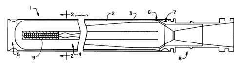
BRIEF DESCRIPTION OF THE DRAWINGS
Fig. 1 is a schematic cross-sectional
side view of a rocket motor having the segment
case of this invention.
Fig. 2 is a schematic cross-sectional,
partly exploded end view of the rocket motor shown
at A-A in Fig. 1.
- 5 -
~: ',.j x.i '.3. ~.~ ~ b
Fig. 3 is a schematic showing details of
the crimp joint 7, snap joint 6 and composite
overwrap 3 as they join nozzle assembly 8.
DESCRIPTION OP PREFERRED EI~ODIMEN'fS
The composite structure of this
invention, in a preferred embodiment a rocket
motor case, is shown in the schematic
representation of a rocket motor in Figs. 1 and 2.
Like numbers indicate like elements in both
Figures.
The rocket motor 1, is comprised of
segmented outer member or segmented rocket case 2,
overwrapped with a polyolefin fiber reinforced
composite overwrap 3. The segmented case 2 is
shown in place in Fig. 1 and in exploded, unmated
position in Fig. 2. The case 2 holds cartridge 5
which contains propellant grain 4. Cartridge 5 is
a thermoplastic which can also function as an
insulator, preferably polyetherimide. See Figs. 1
and 2 where cartridge 5 extends the length of the
propellant grain 4. In this embodiment the case
is held at its lateral or end edge by crimp joint
7 to rocket nozzle assembly 8. Thermoplastic
cartridge 5 forms the opposite closed end of the
rocket motor as shown in Fig. 1, thickened to
render it capable of withstanding pressurization.
Cartridge 5 is connected and seated to the nozzle
assembly 8 by a snap joint 6, as shown. Igniter
assembly 9 is also shown in place in Fig. 1.
Propellant grain 4 has a typical cylindrical shape
with an annular cross-section (hole in the center)
for efficient burning when ignited.
A similar embodiment, shown schematically
in Figure 3, illustrates the manner in which the
snap joint 6 provides for a gas-tight seal between
the cartridge 5 and the nozzle assembly 8. Figure
- 6 -
. 'v ~i
" >.
'~a.~
3 further illustrates the local increase in the
composite overwrap 3 cross-secaion at the crimp
joint 7, which provides the radial restraint
necessary to prevent ejection of the nozzle
assembly 8 upon operation of t:he rocket motor.
Rocket Motor Embodiment
A rocket motor similar to the design of
Figs. 1 and 2 was made and passed the fast cook-
off test MIL-STD-1512. At 120 seconds the
overwrap began to burn and melted away, thereby
allowing the segments to detach from the
propellant grain. The grain then ignited, burned
harmlessly and non-propulsively, which constituted
a successful test. The rocket motor consisted of
a log of conventional propellant (below) machined
and inhibited with an elastomeric coating over
which crimped segments of 17-4 PH high strength
steel were installed and overwrapped with a high
strength polyolefin fiber reinforcement
impregnated with an epoxy resin compounded with a
curing or gelling agent susceptible to W
initiation. The resin was formulated to enable
handling of the motor within minutes, with full
cure attained in 4 days at room temperature. Both
the forward and aft closures had circumferential
grooves to accommodate the crimped segments.
Materials of Construction
Component Material
Reinforcing fiber, in composite High strength pdydefin
Spectra~ 1,000 (Allied-Signal)
Matrix Resin, in composite Epoxy-Loctite 180 (Loctite Corp.)
Curing agent, Loctite 181 (Loctite Corp.)
(ultravidet curable)
Thermoplastic for cartridge Uftem (poiyetherimide) (General Electric)
Case metal High strength steel (17~d PH)
7
h~ '~? v .5. ~ /3 .~3.
Propellant Grain Ammonium Perchdorate-AlumJnum with
Blnder of Hydroxyl Terminated
PdytwGadiene
Method of Assembly of Rocket Motor
Following is a detailed mefihod of
assembly for the rocket motor described above.
1) A cartridge is injection molded from a
thermoplastic such as Ultem. Ultem has been
demonstrated as a replacement for liner and
insulation in rocket motor cases. This material
is sufficiently rigid and provides an excellent
bond to the propellant without surface treatment
or use of a liner. The cartridge could be~
configured with an integral forward closure or
with a separate closure.
2) The propellant grain is cast into the
thermoplastic cartridge and cured.
3) The segments, two clamshell segments or barrel
staves for 3 or more segments, are die stamped out
of steel sheet stock to the desired contour with
crimps at each end. Sheet stock can readily be
held to tight tolerances and the die stamping is a
much less costly process than extruded or rolled
and welded tube.
4) The nozzle/aft closure (steel for short burn
time, or ablative plastic for longer burn time) is
snap fitted onto the thermoplastic cartridge using
a low modulus adhesive such as TI-H-300 on the
interfacing surfaces. The adhesive provides low
pressure sealing and as pressure increases the
sealing surfaces are forced into compression
providing the seal. This seal/interface carries
_ g _
no structural load but only tlhe applied
deformations due to pressure .and thermal loading.
5) The segments, clamshells or barrel staves, are
installed over the cartridge ;assembly.
6) The crimp joints and segments forming a
cylinder are hoop overwrapped with polyolefin
fiber (Spectra 1000) using an ultraviolet (W)
initiated resin (Loctite 180/181). Compatibility
of this fiber and resin has been demonstrated.
The hoop overwrap is sufficient to carry the
entire hoop load and the metal clamshells carry
the axial load. The crimp joints transfer axial
load to the segments (clamshell or barrel stave)
while the fiber overwrap in the crimp prevents
disengagement.
7) The cure is initiated with W light and the
cases can be handled in a few minutes. Full cure
is obtained at room temperatures after 4 days
unattended. The room temperature cure provides a
stress free temperature of the structure near the
middle of the operating range.
8) A proof test is performed on each motor or on
a statistically significant percentage of the
motors.
9) The initiators are installed and the units are
packed out for shipment.
Benefits of This Embodiment
This design enables a high performance
rocket motor assembly meeting insensitive
munitions objectives, with low cost assured thru
minimal part count and process time. '
_ g _
':a :.
p:, '1' ~ 4. r.~ .L .3.
Novel features include: a) composite
overwrap of a structural crimp joint, b) a snap
fit seal and closure alignment. feature, c) low
cost components and low part count, d) case-on-
propellant processing with W initiated resin, e)
an optional component of the casting tooling
becomes the winding mandrel and f) IM performance
is obtained without sacrificing performance or
cost.
The embodiment provides high performance
due to the high strength steel (17-4 PH) segments
and the high specific strength of the composite
overwrap. For insensitive munitions capability
the composite overwrap degrades to virtually no
strength at 230°F, while providing excellent
properties up to 170°F. The snap fit seal assures
nozzle alignment prior to overwrapping.
Many options and variations of the above
preferred embodiment are compatible with essential
features of this invention, including:
1) The case and forward closure could be
assembled and conventional lining, insulation, and
propellant casting techniques could be used.
2) For still higher performance, where IM is not
required, graphite or other fiber could be used.
3) A metal forward closure could be used for
attachments to the payload when operational
loadings are particularly severe.
4) Since propellants bond well to many
thermoplastics, the best choice for the cartridge
materials should be based on motor specifications
such as burn time, propellant temperature, and
mass flow rate. The thermoplastic could be filled
- 10 -
:~:' 1e.n'
with particulate or fibers to tailor the
structural and/or thermal properties.
5) Aluminum, titanium or other high strength
steels could be used instead of 17-4 PH steel for
the clamshells although volumetric loading may
decrease.
6) The crimped segments could be of composite
rather than metallic construction, produced by
molding a laminated assembly of unidirectionally
or bidirectionally reinforced prepreg, staged or
fully cured in advance of construction of the
motor.
7) A low erosion nozzle insert could be used for
higher performance.
8) The design is adaptable to other seal features
such as 0-rings.
While the invention has been described in
connection With what is presently considered to be
the most practical and preferred embodiment, it is
to be understood that the invention is not limited
to the disclosed embodiment, but, on the contrary,
is intended to cover various modifications and
equivalent arrangements included within the spirit
and scope of the appended claims.
- 11 -