Language selection

Search

Patent 2091254 Summary

Third-party information liability

Some of the information on this Web page has been provided by external sources. The Government of Canada is not responsible for the accuracy, reliability or currency of the information supplied by external sources. Users wishing to rely upon this information should consult directly with the source of the information. Content provided by external sources is not subject to official languages, privacy and accessibility requirements.

Claims and Abstract availability

Any discrepancies in the text and image of the Claims and Abstract are due to differing posting times. Text of the Claims and Abstract are posted:

  • At the time the application is open to public inspection;
  • At the time of issue of the patent (grant).
(12) Patent: (11) CA 2091254
(54) English Title: CHECK VALVE
(54) French Title: CLAPET DE RETENUE
Status: Deemed expired
Bibliographic Data
(51) International Patent Classification (IPC):
  • B05B 7/24 (2006.01)
  • B05B 15/00 (2018.01)
  • B05B 15/00 (2006.01)
(72) Inventors :
  • FRANK, PETER L. (United States of America)
(73) Owners :
  • WAGNER SPRAY TECH CORPORATION (United States of America)
(71) Applicants :
(74) Agent: MACRAE & CO.
(74) Associate agent:
(45) Issued: 2000-05-30
(86) PCT Filing Date: 1992-07-09
(87) Open to Public Inspection: 1993-02-18
Examination requested: 1995-11-01
Availability of licence: N/A
(25) Language of filing: English

Patent Cooperation Treaty (PCT): Yes
(86) PCT Filing Number: PCT/US1992/005741
(87) International Publication Number: WO1993/002805
(85) National Entry: 1993-03-08

(30) Application Priority Data:
Application No. Country/Territory Date
740,470 United States of America 1991-08-02

Abstracts

English Abstract


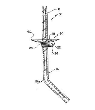
An improved check valve for portable paint cup spray
guns (10) having a radially extending concave diaphragm (20)
surrounding a syphon tube (14) and forming a seal with an
interior surface of a lid (42) of the paint cup (12).


French Abstract

L'invention concerne une soupape d'arrêt améliorée pour pistolets pulvérisateurs de peinture à flacon (10) comportant un diaphragme concave s'étendant radialement (20), entourant un siphon et formant un joint d'étanchéité avec la surface interne du couvercle (42) du flacon de peinture (12).

Claims

Note: Claims are shown in the official language in which they were submitted.


THE EMBODIMENTS OF THE INVENTION IN WHICH AN EXCLUSIVE
PROPERTY OR PRIVILEGE IS CLAIMED ARE DEFINED AS FOLLOWS:
1. An apparatus for preventing the creation of a vacuum
in a paint cup of a paint spray gun, comprising:
a. a syphon tube having a first end and a second
end, adapted to pass through a lid of the paint
cup, and having a tapered portion at the first
end for frictional interengagement with a
tapered receptacle portion in the paint spray
gun such that the frictional interengagement
between the tapered portion of the first end of
the syphon tube and the tapered receptacle
portion in the paint spray gun retains the
syphon tube in the gun;
b. a flexible diaphragm located on the syphon
tube, the diaphragm having:
i) a diameter substantially larger than the
diameter of the syphon tube;
ii) a concave surface facing the first end of
the syphon tube;
iii) a rim portion on the concave surface for
sealing contact with an interior surface
of the lid such that an area of the
sealing contact increases radially as the
first end is inserted into the tapered
receptacle portion.
2. The apparatus of claim 1 further comprises a wire
spring clip type fastening means for securing the
diaphragm to the syphon tube.


3. The apparatus of claim 2 wherein the diaphragm
further comprises a collar surrounding the syphon tube
and the wire spring clip type fastening means surrounds
the collar to secure the diaphragm to the syphon tube.
4. The apparatus of claim 1 wherein the tapered portion
of the first end of the syphon tube has small
circumferential grooves on the exterior surface thereof.
5. The apparatus of claim 1 wherein the second end is
angled with respect to the first end of the syphon tube.
6. The apparatus of claim 1 wherein the diaphragm has
an eccentrically located aperture therethrough having a
diameter sufficiently small to prevent the passage of
liquid through the diaphragm.
7. The apparatus of claim 1 wherein the cross-sectional
thickness of the diaphragm decreases radially toward the
rim such that a wide seal is formed between a peripheral
region of the diaphragm and the interior surface of the
lid.
8. A method of making a check valve apparatus having a
flexible diaphragm attached to a syphon tube, comprising
the steps of:
a. machining a taper on an exterior surface of a
first end of the syphon tube;
b. heating a region of the syphon tube near a
second end of the syphon tube;
c. bending the second end to form an angle with
respect to the syphon tube;


d. sliding the diaphragm having a collar onto the
syphon tube;
e. inserting the first end into a tapered
receptacle of a paint spray gun having a paint
cup lid;
f. sliding the diaphragm toward the first end
until a rim of the diaphragm contacts an
interior surface of the lid; and
g. clamping the collar of the diaphragm against
the syphon tube.
9. A method of positioning a diaphragm on a syphon
tube, comprising the steps of:
a. sliding the diaphragm onto the syphon tube;
b. inserting the syphon tube into a paint spray
gun having a paint cup lid;
c. moving the diaphragm along the syphon tube
until a rim of the diaphragm contacts an
interior surface of the lid and a peripheral
region of decreased cross-sectional thickness
forms a wide seal against an interior surface
of the lid; and
d. clamping the diaphragm to the syphon tube to
prevent further movement of the diaphragm along
the syphon tube.

Description

Note: Descriptions are shown in the official language in which they were submitted.


WO 93/02805 PCT/US92/05741
,~.,.
2091254
-1-
IMPROVED CHECK VALVE
Background of the Invention
This invention relates to high volume low
pressure or HVLP paint spray guns having a paint cup
and utilizing a syphon tube to draw the paint from
the paint cup and deliver it to the gun. In such
guns it has been desirable to provide a passage for
air to enter the paint cup to prevent the creation
of a vacuum which would resist or prevent paint from
being drawn up the suction tube. Such an air
passage, if unprotected, can easily be clogged with
paint, particularly when the gun is used to paint
horizontal surfaces. This need has led to a number
of designs for check valves and other structures for
paint cup spray guns, all of which attempt to both
permit air to enter the paint cup and prevent paint
from exiting the paint cup at that point.
Conventional check valves and other designs
attempting to address this problem have been costly,
complicated, difficult to clean and often have
imperfect operation.
The present invention overcomes
deficiencies of the prior art by providing a simple,
low cost and easily cleanable check valve which both
admits air to the paint cup to prevent creation of a
vacuum and prevents egress of paint or other liquid
from the paint cup through the air venting path.
Brief Description of the Drawincrs
Figure 1 is a side elevation view of a
paint gun assembly showing the present invention.


2091254
-2-
Figure 2 is a side elevation view of a syphon tube
and check valve diaphragm assembly useful in the practice
of the present invention.
Figure 3 is a fragmentary side detail view of a
portion of the spray gun Figure 1.
Figure 4 is a top view of the syphon tube and check
valve diaphragm of the present invention.
Figure 5 is a fragmentary detail view of the tapered
tip of the syphon tube of the present invention.
Figure 6 is a fragmentary section view of a portion
of Figure 1 showing the syphon tube and check valve
diaphragm in a portion wherein the diaphragm is initially
contacting the interior surface of the paint cup lid.
Figure 7 is a view similar to Figure 6, except with
the check valve diaphragm fully engaging the paint cup
lid.
Figure 8 is a fragmentary bottom view of the
diaphragm of Figure 4.
Detailed Description
Referring now to Figure 1, a paint gun assembly 10
may be seen. Gun 10 preferably has a paint cup 12 from
which paint is drawn by a syphon tube 14. Referring now
also to Figures 2, 4 and 5 tube 14 is preferably 0.375"
in diameter, formed of nylon and manufactured by heat
forming an angle 16 partially along tube 14 and further
by machining a taper having a taper angle 34 of 1° 40' ~
0° 15' at a proximal or first end 18 of tube 14. It is
to be understood that tapered end 18 has a relatively
coarse machine finish as indicated in Figure 5. Syphon
tube 14 preferably carries a diaphragm 20 formed of low
density polyethylene and having a relatively wide flange
portion 22 preferably having a 2.4" diameter carried by
an integral collar or hub 24. Diaphragm 20 preferably is
0.050" thick at hub 24. Hub 24 is preferably secured to
tube 14 by a wire spring clip 26. In one embodiment,
flange 22 preferably has an aperture 28 drilled through
VLS:jj
%'a.:.


r..
_3_ 2 0 9 1 2 5 4
it in an eccentric location. Hole 28 is preferably
0.031" ~ 0.004" in diameter. It has been found that
using this diameter for aperture 28 prevents egress of
liquid from the interior of paint cup 12 through aperture
28.
In an alternative embodiment, hole 28 may be omitted
from flange 22.
Referring now more particularly to Figures 3 and 5,
paint gun 10 has a neck 30 having a tapered socket 32
molded therein. Socket 32 preferably has a taper angle
equal to the taper angle of tube 14. This angle forms a
"self-locking" taper such as may be achieved with taper
angles of approximately 4° or less.
It is to be understood that assembly 36, made up of
syphon tube 14, diaphragm 20, and clip 26, is retained in
gun 10 by the interaction of the tapered socket 32
frictionally engaging tapered tip 18 as shown in Figure
3.
Referring now again more particularly to Figure 5,
tapered end 18 is preferably formed by machining tube 14
which typically results in machining marks or grooves 38.
The irregular surface formed by marks 38, although not
necessary, is believed to aid in the retention and
release characteristics between tip 18 and socket 32.
It is further to be understood that (as may be seen
most clearly in Figure 2) diaphragm 20 has a tapered
cross section with the outer periphery 40 having a
gradually reduced or "feathered" cross section. Such a
cross section provides flexibility to the outer
peripheral region
VLS:jj


WO 93/02805 PCT/US92/05741
201254 - 4
40 of diaphragm 20. Such flexibility assures a
consistent seal between region 40 and lid 42.
Referring now to Figure 6, as assembly 36
is inserted in gun 10, outer periphery 40 will
initially contact lid 42. Assembly 36 is preferably
inserted further into,socket 32 resulting in
diaphragm 20 deforming to the condition shown in
Figure 7 which shows assembly 36 fully installed in
gun 10. In Figure 7, peripheral region 40 is either
flat or slightly convex, while in Figure 6 (and in
Figure 2) peripheral region 40 is on the concave
curvature of diaphragm 20. As may be seen most
clearly in Figure 7, when assembly 36 is fully
installed and seated against lid 42, a relatively
wide seal is accomplished between region 40 and lid
42. This is illustrated graphically in Figure 8
where region 40 is speckled to indicate the wide
seal band or region that exists. Furthermore, this
wide seal is at a relatively highly flexible region
of diaphragm 20. In the embodiment not using
aperture 28, the peripheral region 40 of diaphragm
20 will flex away from lid 42 to allow air to enter
cup 12, but will reseal against lid 42 to prevent
paint from leaking out of cup 12 via seal or region
40.
To assemble diaphragm 20 to tube 14, it
has been found desirable to use a fixture in the
following manner. First, tube 14 is manufactured
and diaphragm 20 is installed on tube 14 relatively
closer to bend or angle 16 than in the calibrated or
final assembly position. Next the assembly of tube
14 and diaphragm 20 is inserted into socket 32 of
gun 10. Next spring clip 26 is expanded to allow
movement along tube 14, and a fixture is used to
position diaphragm 20 with respect to lid 42 to
achieve the seal as shown in Figure 8. Finally,
clip 26 is released, thus clamping hub 24 and hence


WO 93/02805 Z 0 912 5 4 p~/US92/05741
- 5 -
diaphragm 20 to tube 14, thus calibrating the
position of diaphragm 20 with respect to tube 14 and
the particular gun 10 with which it is to be used.
The invention is not to be taken as
limited to all of the details thereof as
modifications and variations thereof may be made
without departing from the spirit or scope of the
invention.

Representative Drawing
A single figure which represents the drawing illustrating the invention.
Administrative Status

For a clearer understanding of the status of the application/patent presented on this page, the site Disclaimer , as well as the definitions for Patent , Administrative Status , Maintenance Fee  and Payment History  should be consulted.

Administrative Status

Title Date
Forecasted Issue Date 2000-05-30
(86) PCT Filing Date 1992-07-09
(87) PCT Publication Date 1993-02-18
(85) National Entry 1993-03-08
Examination Requested 1995-11-01
(45) Issued 2000-05-30
Deemed Expired 2012-07-09
Correction of Expired 2012-12-02

Abandonment History

There is no abandonment history.

Payment History

Fee Type Anniversary Year Due Date Amount Paid Paid Date
Application Fee $0.00 1993-03-08
Registration of a document - section 124 $0.00 1993-09-10
Maintenance Fee - Application - New Act 2 1994-07-11 $100.00 1994-04-12
Maintenance Fee - Application - New Act 3 1995-07-10 $100.00 1995-03-29
Maintenance Fee - Application - New Act 4 1996-07-09 $100.00 1996-06-12
Maintenance Fee - Application - New Act 5 1997-07-09 $150.00 1997-06-26
Maintenance Fee - Application - New Act 6 1998-07-09 $150.00 1998-07-09
Maintenance Fee - Application - New Act 7 1999-07-09 $150.00 1999-07-06
Final Fee $300.00 2000-02-28
Maintenance Fee - Patent - New Act 8 2000-07-10 $150.00 2000-06-22
Maintenance Fee - Patent - New Act 9 2001-07-09 $150.00 2001-06-15
Maintenance Fee - Patent - New Act 10 2002-07-09 $200.00 2002-06-19
Maintenance Fee - Patent - New Act 11 2003-07-09 $200.00 2003-06-13
Maintenance Fee - Patent - New Act 12 2004-07-09 $250.00 2004-06-02
Maintenance Fee - Patent - New Act 13 2005-07-11 $250.00 2005-07-11
Maintenance Fee - Patent - New Act 14 2006-07-10 $250.00 2006-05-18
Maintenance Fee - Patent - New Act 15 2007-07-09 $450.00 2007-06-07
Maintenance Fee - Patent - New Act 16 2008-07-09 $450.00 2008-06-18
Maintenance Fee - Patent - New Act 17 2009-07-09 $450.00 2009-06-19
Maintenance Fee - Patent - New Act 18 2010-07-09 $450.00 2010-06-18
Owners on Record

Note: Records showing the ownership history in alphabetical order.

Current Owners on Record
WAGNER SPRAY TECH CORPORATION
Past Owners on Record
FRANK, PETER L.
Past Owners that do not appear in the "Owners on Record" listing will appear in other documentation within the application.
Documents

To view selected files, please enter reCAPTCHA code :


To view images, click a link in the Document Description column. To download the documents, select one or more checkboxes in the first column and then click the "Download Selected in PDF format (Zip Archive)" or the "Download Selected as Single PDF" button.

List of published and non-published patent-specific documents on the CPD .

If you have any difficulty accessing content, you can call the Client Service Centre at 1-866-997-1936 or send them an e-mail at CIPO Client Service Centre.


Document
Description 
Date
(yyyy-mm-dd) 
Number of pages   Size of Image (KB) 
Cover Page 2000-06-29 2 51
Cover Page 1994-04-30 1 23
Abstract 1995-08-17 1 60
Representative Drawing 2000-05-03 1 7
Claims 1994-04-30 3 104
Drawings 1994-04-30 2 92
Description 1994-04-30 5 211
Description 1999-08-25 5 182
Claims 1999-08-25 3 91
Cover Page 2000-05-03 1 28
Representative Drawing 1998-06-25 1 24
Cover Page 2000-06-29 1 28
Correspondence 2000-06-29 2 40
Correspondence 2000-02-28 1 27
Correspondence 2000-06-12 2 74
International Preliminary Examination Report 1993-03-08 4 249
Prosecution Correspondence 1995-11-01 1 25
Office Letter 1995-11-28 1 43
Prosecution Correspondence 1998-01-21 7 239
Examiner Requisition 1997-09-26 3 132
Fees 1996-06-12 1 56
Fees 1995-03-29 1 42
Fees 1994-04-12 1 55