Note: Descriptions are shown in the official language in which they were submitted.
2091331
~rT~T~nrTNn OF THE INVENTION
Fleld of l'hf' Invention
This invention relates to an assembly of
for a molten -Arh~n~ fuel cell comprising a
laminate of at least one electrode ~nd an electrolyte matrix
and a process for making the assembly.
DescriT~tion o the Prior Art
Known molten carbonate fuel cells consist of
cathodo and an anode between which is disposed an
electrolyte matrix tape formed from a slurry of lithium
~luminate in an organic vehicle containing a plastic binder
and additives that impart good slurry properties. The
slurry is o~t onto A flat Teflon6 substrate by a dootor
blade and the organic Dolvent is allowed to c~ JVL~e~ The
dried tapo is flexible as a result of the 1. ln;n~ plastic
binder which is removed by thermal degradation after
~ssembly of the fuel cell. Single or multi-piece matrix
tapes are ~ T in the fuel oell with a cathode on one
side anq an anode on the other side. The matrix is
cd with molten carbonate, contained in an
electrolyte tape or in the pores of the porous electrode, by
capillary action during heat up of the fuel cell. As the
fuel cell is heated, the plastic binder in the matrix is
removed and the carbonate in the eleotrolyte tape or the
~lectrode becomes molten and is wicked into the matrix. The
fuel cells are typically combined into a fuel cell stack and
have positioned between them a separator plate which
8c~)a~ the anode of one fuel cell from the cathode o~ the
adjacent fuel cell.
~ ore ~ f~ 11y~ a molten carbonate fuel cell
consists of an eleotrolyte DL~ u~ oontaining lithium
aluminate and a mixture of alkali carbonates. A cathodo and
IGT-1259 2 ~ esb/9
'
2~
an anode are attached to the two faceG o~f the matrix, one on
each side thereof. Each electrode is contained within a
metal plate compartment, the plate resemollng a framed
D~LUl;~ULe with a periphoral frame acting as a "wet seal".
The electrodes fit withln the "active area" which is the
~rea inside the frame and the Qlectrode height is flush with
the "wet seal" frame. The matrix extends all the way to the
outer edge of the "wet seal'~. At the fuel cell operating
ULe of about 650'C, the molten electrolytc form~ a
seal against the "wet seal" frame ~o prevent gas leakage
from the electrode compartment~. Normally, the internal
edges of the anode ~md cathode wet seal frames are aligned
with each othcr.
U.S. Patent 4,538,348 teaches casting electrolyte
matrix t~pes rrom a mixture of inert particles small~r than
one micron, such as lithium aluminate, corrosion rosistant
ceramic particulates ~or crack resistance and a temporary
plastic binder, all heated "in cell" to remove the binder.
Upon cell assembly, active electrolyte is furnished by a
prefilled anode.
There arc several diDddv~ L I-les associated with
ccnventional fuel cell assembly and start-up. "In-cell"
binder remcval and electrolyte i ~-,ation of the matrix
requires a prclonged and care~fully controlled process. In
addition, the completed fuel cell requires the formation of
a "wet sQal" frame by the molten el~ctrolyte with the
peripheral frame of the metal plate . I ~ containing
each electrcde to prevent gas leakage into the electrode
~ D Finally, the clamping force applied to the
cell oasily causes cracking of the matrix resulting in gas
UrvDDuvcL between electrodes.
D~nnifl~ation of at least the edge portions of
IGT--1259 3 esb/9
~'
., ~
,. ~
2091331 - -~
fuel cell is known for improving the gas edge
seal ~or gas porous fuel cell ~D. U.S. Patent
4,269,642 and related U.S. Patent 4,365,008 teach an
improved gas edge seal ~or gas porous fuel cell
~nd a process for fabrlcating such fuel cell . in
which a fully graphitized gas porous, resin honde~7 carbon
~iber 7he~th h~ving edge portions which are more dense than
~ central portion i8 formed by forming an i,.~ iAte
prcduct compriaing c~rbon fibers and a I h ~ t~ ing resin
which is not fully cured, the 1nt iAte product having
increased thi~ kn~c~ along its edges, simultaneovsiy
densifying at least the edge portions by compressing them to
~ hi~ Icn~5 which ig 5ubgtantially the sane as the desired
final fhi~-lrn~a~ of the central portion of the 1~,
curing the part and further heating the part to carbonizQ
the resin Imd L ~ y graphitize the resin and carbon
f ibers .
U. S . Patent 4, 652, 502 and related U. S . P~tent
4,756,981 disclose a process fcr making porouD plates for an
ele~ iCA7 cell in which the peripheral edge regions of
the plates are provided with smaller pores than the
~, inr7~r of the plate and edge sealing is effected by a
s~ n~ n of sealing material forced into the edge region
producing an edge region having a higher density than the
L~ ~nin~ plate. Sinilarly, U.s. Patent 4,786,568 teaches
an electrcde plate assembly for use in a fuel cell power
plant in which the edges of a porous substrate plate are
A~n~ifi~y~ by i .y"aLing a suspension of finely divided
material in the form of an "ink" in~o the interstitial
spaces in the plate edges to form an integral fille.- band
around ~ catalyst layer which has been previously applied to
one surf~ce of the a~Dl.ral.~: plate. A different approach is
IG~-1259 4 esb/g
, .
2~91331
!- taught by U.S. Patent 4,659,635 in which an improved porous
matrix for cont2ining molton carbonate electrolyte in a fuel
cell stack consists of a substantially flat sheet or porous
cernmic material having a generally smaller pore sizQ
average in the central body of the sheet and a generally
larger second pore size aver~ge in the edge portion of the
sheet, the lnrger pore sizes upon wetting with molten
u..LLu..c.~e leaving void a ma~or portion of the internal
porosity .
sTTMM1~DY OF TUT~ JNVENTION
It i8 an object of this invention to facilltate
the assembly and start-up of a molten carbonate fuel cell
and stack.
It is an object of this invention to provide an
assembly of for ~ molten carbonate fuel cell
cnnt~n~n7 little or no organic binders to be burned off "in
cell" .
It is yet another object of this invention to
provlde an assembly of for a molten carbonate
fuel cell having a partly to fully ~ ,.ate~ matrix
~LU~_~ULCI prior to insertion into ~ fuel cell.
It is yet another ob~ect of this invention to
provide an assembly of . for a molten carbonate
fuel cell in which gas leakage into the electrode
~ " of the fuel cell is prevented.
It is yet another ob~ect of this invention to
provide an assembly of ~ for a molten carbonate
fuel cell in which the matrix is p-c~ d from cracking at
the wet seaVactive area transition, thereby preventing gas
~;LV~ L between the electrodes.
These and other ob~ects are achieved in a..u.d~
with this invention in an asgembly of fuel ce 1 ,~
IGT-1259 5 esb/9
2091~3~
comprising, in ac~ a.~.~ with one ' ~ nt of this
invention, ~ compo3ite active electrolyte-matrix tape
comprising about 45 to about 85 volume peraent active
electrolyte distributed within and upon about 15 to about 50
volume percent matrix particle3 and having an active area
and ~ peripheral wet seal area, an anode in contact with a
iace of the composite active electrolyte-matrix tape and/or
a cathode in contact with an opposite face of th~ compo3ite
active electrolyte-matrix tape, the anode and cat~.ade
~Yt.~n~l 1 n7 bQyond the periphery of the active area of the
composite Iwtive electrolyte-matri~ tape and ~nnt~t~n~ the
peripheral w~t seal area thereof, and a portion o~ the
p~r~rhor~l wet seal area oi the composite active
electrolyte-matrix tape forming a frame around the anode and
cathode whereby the i~ce of the electrode facing away from
the composite active electrolyte-matrix tape is flush with
the frame formed by the peripheral wet seal area.
More ~r~1f~o:~lly~ the electrolyte matrix of the
assembly of ~ ~or a fuel cell in al:.uld.lllc~ with
this invention is in the form of a tape comprising a matrix
of lithium aluminate and an active electrolyte comprising
lithium carbonate and at least one carbonate selected from
the group consisting of potassium ~ c~LL~ and sodium
.~LLu..c,~e cut to the exact size of an entire separator
plate. The electrolytc matrix has an active area and a
r~r~rh~r~ll wet seal area surrounding the active area. The
anode and the cathode, both of which are smaller than the
electrolyte matrix, are po3itioned one on each face of the
electrolyte matrix. The electrodes are sized such that when
placed on the face of the electroly~e matrix, the peripheral
edges of the electrodes extend beyond the active area of the
electrolyte matrix and cover a portion of the peripheral wet
IG~-1259 6 esb/9
a ' ~
., .
2~91~31
seal area, forming a laminate structure. Ilpon heating this
- laminate ~,~.u. ~u--, to a t ~ of 500-C and applying a
compaction force of 10-50 p8i, the binder in the ~atrix is
rcmoved and the hot matrix is rlc~n~1f~d~ foroing the
electrodes to sink into the heat-softened matrix 80 that the
ef~l cell hag the expoged edges of the matrix aoting ns
~ wet seal ag~inst the metal plate surrounding the ~ssembly
and thus proteots the electrode edges from oxidat~on.
In a ~ v.d~ e with another: ~ of this
invention, a matrix tape of lithium aluminate cut to the
exact size of the entire fuel cell plate and having an
active ~Irea and a peripheral wet seal area i5 disposed
between an anode and a cathode, both of which are smaller
than the matrix, but which extend beyond the active area of
the matrix when in contact with the face of the m~ltrix tape.
The anode and/or the cathode is impregnated with mixed
.~L,.,...,L~ electrolyte which wicks into the matrix tape when
the laminate ~u~,Lu~e~ is heated to a temperature of 500-C
and t-~d to densify the hot matrix.
It will be apparent to those skilled in the art
that parti~l laminate ~-.u~;Lu.~_, in addition to the one
piece laminate ~I~LU~;LU~_ described hereinabove, may be used
singly with other ~ or used together in a fuel
oell. For example, a cathode/matrix laminate may be u3ed
with a separate anode; an anode/matrix laminate may be used
with a separate cathode: a cathode/matrix laminate may be
used with an anode/matrix laminate; a cathode,'matrix
laminate may be used with another matrix and a separate
anode: and an anode/matrix laminate may be used with another
matrix and a separate cathode.
A process for making a laminated ~uel cell
~ in aocordance with this invention comprises
IGT-1259 7 esb/9
.,,, ~
2091331
placlng an anode ad~acent one side of a composite active
olectrolyte-matrix tape and/or a cathode ad; acent the
opposite side of the composite active electrolyte-l~atrix
tape, the composite active electrolyte-matrix tape having an
nctivQ ~rea ~nd a peripheral wet seal area and the anode
nnd/or cnthode extending beyond a periphery of the active
nrea ~nd cnn1~CI il~J the periphernl wet seal area, thereby
forming n lnminate ~LLU~-ULe. The laminate structure is
heated to about 500-C to remove the binder from the matrix
tape. A 1nn forcQ of 10-50 psi is applied to the
1amiDate ~LLUU~UL~ at about 500'C to densify the matrix,
forcing the electrodes to sink into the heat-softened
matrix. The . i nn ~orce i~ y released and
the matrix nllowed to cool. It is an important feature of
this invention that the entire processing of the laminate
may be carried out "out-of-cell", thereby avoiding the
prolonged and carefully controlled process re~luired of in-
cell processing.
RRT~ ccRTpTIoN CF ~IIHF nRl~WTN('..C
These and other objects and features of the
invention will be apparent from the following detailed
description of the invention read in conjunction with the
drawings, wherein:
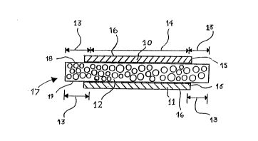
Fig. 1 is a l;L~ inn:~l side view of a
laminate ~LL~ LuL~ in ac~.,L-I~ with one ~ ; of this
invention prior to heating nnd compaction: and
Fig. 2 is a ~:L~ -l Inn~1 8ide view of a
laminate ~LLu~LuL~ in a~.:uLdc,i.. :~ with one . i of this
invention after having been heated and . -t~.
F ~ r:~ RMRnDTM~lTS
Laminate ~LLU.,LUL~:: 17 in accordance with one
' 'ir ' of thig invention is shown prior to assembly in
IGT-lz59 8 esb/9
2o~l33l
Plig. 1. Laminate structure 17 comprises electrolyte matrix
12, preferably a composite active electrolyte-matrix tape
~ormed as detailed beloN or a matrix tape rormed rrOm a
slurry of lithium ~1 'nAt~ in an organic solvent ~ont~in~n7
a plastic binder and additives that impart good slurry
properties. Electrolyte matrix 12 has a centralized active
area designated by arrows 14 and a peripheral wet seal area
designated by arrows 13. In accordance with a pre~erred
1 ~ o~ this invention, electrolyte nat:rix -2 i8 in
the ~orm of a composite active electrolyte-matrix tape
comprising a m~trix Or lithium aluminate and an active
electrolyte comprising a mixture or' lithium ~ L' Le and at
least one carbonate selected ~rom the group consisting of
potassium ~ e and sodium carbonate distributed within
~nd upon the matrix. The composite active electrolyte-
matrix t~pe comprises about 45 to about 85 volume percent
active electrolyte distributed within and upon about 15 to
about 55 volume percent matrix particles. The active
electrolyte and the matrix particles comprise about 30 to
about ~0 volume percent of the tape with about 30 to about
70 volume percent being void space.
In accordance with one ~ ~ o~ this
invention, anode 11 is in contact with matrix ~ace 19 of
electrolyte matrix 12 and cathode 10 is in contact with
opposite matrix face 18 of electrolyte matrix 12. Both
anode 11 and cathode 10 extend beyond the periphery o~
~ctive area o~ electrolyte matrix 12 designated by arrows 14
~nd contact the peripheral wet seal area of electrolyte
matrix 12 designated by arrows 13.
In acvvLd~ e, with another ~r ~ o~ this
invention, laminate D~LU~.d.UL~: 17 comprises only anode 11 in
contact with matrix face 19 of electrolyte matrix 12 and in
IGT-1259 9 esb/9
~ ~,--.,,r . . ,
2V~13~1
JLdea~ with yet zmother: ; ~ of this invention,
lamin~te ~Lu~ LUL~ 17 comprise~ only cathodo lo in contact
with opposite matrix ~ace 18 o~ electrolyte matriY 12.
Laminate ~LU~;~ULe~ 17 as shown in Fig. 1 i8 heated
to ~ ~-UL ~ of ~bout 500-C and ~ubjected to pL~ ~
of about 10 to ~bout 50 psi resulting in the conf;~r~;nn
shown in Fig. 2.
AB shown in Fig. 2, ~node 11 and cathode 10 are
embedded within electrclyte matrix 12. A portion of the
peripheral wet seal area designated by arrows 13 of
electrolyte matrix lZ ~orms frame 20 around ~node 11 and
cathode lO such that when laminate structure 17 18
pcsitioned in a fuel cell, electrode edges 15 are not
expo~ed to the ~ . In addition, where anode 11 and
c~thcde lO extend beyond the active area o~ matrix 12
designated by arrows 14 and contact the peripheral wet seal
area of electrolyte matrix 12 designated by arrows 13, a
seal is effected by that portion of the wet seal area which
i5 in contact with the faces of anode 11 and cathode 10
facing electrolyte matrix 12. In contrast to conYentional
cell assembly where the electrodes Eit completely within the
active area of the matrix and are framed by the entire
peripher~l wet seal area thereby pe~mitting gas c~ ossover
between electrodes when the matrix cracks in the areas of
the edges of the anode and cathode, the portions of anode ll
and cathode lO ~ n~ f; ng the peripheral wet seal area o~
electrolyte matriY 12 and forming a ~eal therewith bridge
the gap between the active area and wet seal area
tran~ition, thereby preventing ga~ ~L~Jd~ L between anode
ll and cathode 10 in the event of matrix cracking.
In a.a ~ lc~ . with one ; ~ cf this
invention, anode ll and cathode 10 comprise a plurality of
IGT-1259 10 esb/9
..;.~ . .
. ~
2 ~ 3 1
layers of electrodes to build up thickness around the aotive
, area of matrix 12. Anode 11 and oathode 10 have a preferred
1-h;~kn~c~ of about 5 to about 50 mils.
In a~ .u., with another -~r^n~ of this
lnvention electrolyte matrix 12 comprlses a plur~Lity of
~llectrolyte matrix tapes l~m; n~t~l together. In a~ -. U~
with yet another ' '; ~ of this invention, electrolyte
matrix 12 comprises a singlo electrolyte matrix tape. The
preferred thickness of electrolyte matrix 12 is about 20
mils to about 120 mils.
In accordance with one ' '~ L of this
inveDtion, anode 11 and/or cathodc 10 is;, e~ ud with an
~cti~e electrolyte comprising a mixture of lithium carbonate
~nd at least one carbonate selected from the group
consisting of potP~e j ' I,u and sodium carbonate .
During the heating and , ' lnn of laminate :~L1U~ ULU 17,
the active electrolyte wicks into the active area of matrix
12 .
In a process for making a laminatcd fucl ccll
in a~-,.,Ld~n ,~ with onc l~mhn~l ~ ' of this
invcntion, ~ composite active electrolyte-matrix tape is
formed by mixing powders of active electrolyte material and
high 3urface area matrix material; heating the mixture to
above the melting point of the active electrolytc material
forming a composite active electrolyte-matrix; cooling and
grinding the composite active electrolytc-matrix to a f ine
powder; ~l;crprn;n~ and milling the composite active
electrolyte-matrix fine powder in a liquid with binder
suitable for tape casting; ~^g~nn;n~ the dispersion of
composite active electrolyte-matrix fine powdcr in a liquid
with binder; casting the degassed dispersion of the
ccmposite active electrolyte-matrix fine pcwder in liquid
IG~-1259 11 esb/9
2~91331
into a tape; and evaporating the liquid to form a dry,
flexible composito active electrolyte-matrix tape. A
plurality of these tapes may be laminated togetheI to form a
single lP-;nAt~d ccmpcsite active electrolyto-matrix tape Or
4 suitable thicknoss ~or the desired fuel cell active
electrolyte-natrix. Lamination may be achieved by rolling
or pressing together multiple tapes or by multiple layer
tape casting.
In a.J~ al~ .. with 4ncther: ; ~ o~ this
invention, electrolyte matrix 12 is in the form of tapes
m4de ~rom a slurry o~ lithium aluminate in an organic
vehicle cnntl~1nin~ a plastic binder and the additives that
impart good slurry properties. The slurry is cast onto a
~lat Teflon- ~.ubD~L4~e by a doctor blade and the organic
solvent is allowed to evaporate. The dried tape is flexible
48 a result Or the L~ ining plastic binder.
To form laminate structure 17, ancde ll is placed
4d~accnt one side Or electrolyte matrix 12 hzving an active
area 4nd 4a peripheral wet seal area and/or cathode lO is
placed 4djacent to the opposite side of electrolyte matrix
12 such that anode 11 and cathode 10 extend beyond the
periphery of the 4ctive area o~ electrolyte matrix 12 in
contact with the peripheral wet seal 4rea, thereby forming
14minate A~LU- ~UL~ 1~. Anode 11 and cathcde 10 are cut to a
sise and planar geometry larger than the active area of
electrolyte matrix 12 but smaller than the entire area of
Qlectrolyte matrix 12. Exact Al; ~ of anode 11 and ~
cathode 10 is not ne~ e~DaLy and may not be desirable.
However, both electrodes must not extend beyond the
periphery Or electrolyte matrix 12 and the wi~th o~ any
u-lcuv~:L~d portion Or electrolyto matrix 12 must be less than
the width o~ the peripheral wet seal area o~ electrolyte
IGT-1259 12 esb/9
2~gl~3I
matrix 12 to ensure that each electrode covers part oS the
peripher~l wet seal area entircly around the active area of
olectrolyte matrix 12.
L~DinAte structure 1~ thus formed i9 heated to a
temperature of ~Ibout 400-C to nbout 650-C, causing
cloctrolyte matrix 12 to soften. In accordance with one
-1 of this invention, electrolyte embodded within
~node 11 and/or cathode 10 becomes molten and wicJcr into
electrolyte matrix 12.
At a l Cl~ULe of about 400'C to about 650-C, a,
l~ force of about 10 to about 50 psi i8 applied to
l~minate L~LLU~:~UL~ 17 forcing anode 11 and cathode 10 to
sink into softened electrolyte matrix 12. This ~ ~ nn
force is ~pplied until the faces 14 of ~node 11 and cathode
lo facing away from electrolyte matrix 12 are flush with a
portion of the peripheral wet seal area of electrolyte
matrix 12 ~Yt~nrl~n~ beyond the periphery of anode 11 and
cathcde 10, the peripheral wet seal area forming frame 20
~round anode 11 and cathode 10. In this manner, edges 15 of
~node 11 and c~thode lo edges 15 of anode 11 and cathode 10
are protected from oxidation in the assembled fuel cell.
When facos 16 of anode 11 and cathode 10 are flush with the
peripheral wet seal area of electrolyte matrix 12, the
compaction force i8 released and the now d~n~1fi~d laminate
~LLU~;LULe 17 iB cooled. Laminate structure 17 is then ready
for i~ L~ L~LlOn into a fuel cell.
Whlle in the foregoing ~p~ f~ration this
invention has been described in relation to certain
preferred 1 thereof, and may details have been ~et
forth for the purpose of illustration, it will be apparent
to those skilled in the art that the invention is
~usceptible to additional ` 1 L~. and that certain of
IGT-1259 13 esb/9
2~91331
the detallD described herein c~n be varied considerably
without departing ~ro~ the basic principleG of the
Invontl n.
,~
IGT-1259 14 eGb/9