Note: Descriptions are shown in the official language in which they were submitted.
,, ,, ,,~ '', ~~ ''a ..
ws ~, .' r >:...
_1_
UTILITY METER TRANSPONDER/ANTENNA ASSEMBLY
FOR LJNDERGROUND INSTALLATIONS
Back~~ round of the Invention
1. Field of the Invention
The invention relates to the remote reading of utility meters which
are located outside of a building in an underground enclosure.
2. Description of the Background Art
In moderate climate zones, utility meters are located in subsurface
enclosures in areas adjacent to residences or other dwellings. Such enclo-
sores are referred to as "pits." An example of such enclosure is illustrated
in Haase et al., U.S. Pat. No. 1,781,280.
In Edwards et al., EPO Publication No. 0 252 184, meter data is
transmitted from a utility meter in an underground pit to an electronic
collection unit carried by a meter reading person. Scuilli, U.S. Pat. No.
4,758,836, shows an electronic metering unit which uses the inductive
coupling method of the metering unit of Edwards et al.
More specifically, the electronic metering unit in Edwards et al. is
electrically connected through a cable to a first inductive coil, which is po-
sitioned in an assembly that attaches to the pit lid. A second coil is located
in the tip of a wand carried by a meter reading person. The meter reading
person positions the tip of the wand in an opening in the pit lid assembly.
This permits the coupling of signals by which the meter data is transmit-
ted from the electronic meter to the collection unit.
There are a number of limitations in the prior art. First, the induc-
five coupling system does not provide a completely remote system as the '
meter reading person must approach relatively close to the pit lid to ob-
tain a reading. Second, underground equipment must be made weather-
resistant to varying temperature and moisture conditions. This is particu-
larly true of electronic equipment to be used in underground enclosures.
The assembly for the inductive coupling system discussed above
was not sealed against the elements. There was one opening for commu-
-2- ~, '~~~i ~,a. r~ ~a I.~~'-
nication with the pit to allow a connection of a connecting cable and a sec-
ond opening at the top to allow coupling to the second inductive coil.
Radio frequency meter reading systems have been known, but such
prior radio frequency systems have been limited in use to buildings and
above ground installations because the components were not sufficiently
weather-resistant for use in underground pit enclosures.
Another limitation is that pit enclosures, being typically made of
metal, present possible interference with radio transmission and recep-
tion.
The present invention is intended to overcome the limitations of
the prior art.
The invention is incorporated in an assembly comprising a com-
pletely enelosed, low profile, antenna housing which attaches to the lid of
a subsurface pit enclosure, an antenna disposed within the antenna hous-
ing and projecting above the pit lid for transmitting radio signals to a col-
lection unit, a transponder enclosure within the pit, a transponder within
the transponder enclosure for converting data signals received from an
electronic utility meter to radio frequency signals for transmission
through the antenna, and a sealed connection between the antenna enclo-
sure and the transponder enclosure.
In a preferred embodiment the antenna enclosure and transponder
enclosure are coupled together, a first seal is used to seal the transponder
enclosure, and a second seal is used to seal the connection of the antenna
enclosure to the transponder enclosure.
The invention provides a fully remote meter reading system with
weather-resistant features that permit installation of units in outdoor un-
derground enclosures.
Other objects and advantages, besides those discussed above, will be
apparent to those of ordinary skill in the art from the description of the
preferred embodiment which follows. In the description, reference is
made to the accompanying drawings, which form a part hereof, and
which illustrate examples of the invention. Such examples, however, are
not exhaustive of the various embodiments of the invention, and, there
~"p P
7 ~ ~~ '~
fore, reference is made to the claims which follow the description for de-
termining the scope of the invention.
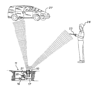
Fig. 1 is a general pictorial illustration showing the environment of
the present invention;
Fig. 2 is a side view in elevation of a preferred embodiment of an
assembly of the present invention;
Fig. 3 is a exploded perspective view of the top portion of the as-
sembly of Fig. 2; and
Fig. 4 is sectional view of the assembly of Fig. 2.
Detailed Descrspfion of the Pr f rr d ynbodimP"r
Referring to Figs. 1 and 2, the invention is incorporated in a pit
transponder and antenna assembly 10 located in a subsurface pit enclosure
11. The pit is typically made of metal and includes sidewalls 13, 14 and a
lid 15 which is removable to open the enclosure for access. A bottom wall
12 is optional. The pit enclosure 11 is located along the route of water
supply pipe 17. A water meter housing 16 is connected in the water sup-
ply line 17, using hex-head nuts 18, 19 which are sealed in a conventional
manner against leaks at the connecting points. An electronic water meter
unit 20 is mounted on top of the housing 16. The electronic meter 20 is
preferably a meter including the High Resolution Transmitter offered by
Badger Meter, Inc., the assignee of the present invention. This transmitter
is described in Strobel et al., U.S. Patent No. 4,868,566, entitled "Flexible
Piezoelectric Switch Activated Metering Pulse Generators."
The water meter 20 connects via a twisted pair, shielded cable 21 to
the transponder and antenna assembly 10, which in this embodiment is
attached to, and hangs down from the pit lid 15. A cap 22 is positioned
above the pit lid 15, and as seen in Fig. 4, an antenna 23 is positioned
within an antenna shroud 24 to extend above the pit lid 15. The cap 22 is
made of plastic and antenna shroud 24 is made of an ABS polycarbonate
blend plastic, so as not to interfere with radio waves which emanate into
the atmosphere.
As seen in Fig. 1, the transponder/antenna assembly 10 communi-
cates via radio waves with a handheld collection unit 25 carried by a meter
reading person 26 or a collection unit carried in a vehicle 27. The collec-
tion unit 25 sends interrogation signals to each transponder/antenna as-
sembly 10 (representing a customer meter) in the form of a digitally en
coded message with a unique identification number and an error code for
checking the data at the receiving end. In response to this message, the
transponder/antenna assembly 10 transmits a return message which in
cludes an identification code, meter reading data, and an error code for
checking the data at the receiving end.
The handheld collection unit 25 has a range of approximately 50
feet and has storage for up to 1,000 readings. The collection unit (not seen)
in vehicle 27 has a range of 150 feet and can process and store up to 1,800
readings per minute.
Referring to Figs. 2, 3 and 4 the antenna shroud 24 has a threaded
stem 28 with a lower end and an upper end. When the transpon-
der/antenna assembly 10 is installed, the threaded stem 28 extends
through a hole 29 in the pit lid 15 in Fig. 2. The cap 22 has a circular open-
ing with an inside circumferential thread 30 that engages the thread 31 on
the stem 28 as seen in Fig. 4. The cap 22 is screwed onto the threaded stem
28 and has a flat bottom side which engages a top side of the pit lid 15 to
suspend the transponder/antenna assembly 10 from the pit lid 15. The
top side of the cap 22 has a central portion 32 with a slightly curved profile
as seen in Fig. 4 and a bevel portion 33 seen in Figs. 3 and 4 which runs
around the central portion and extends outward to the outer rim. The cap
22 also has a hexagonal opening 34 through the center to receive a hex-
sided anti-tamper plug 35. Stem 28 includes hex socket 45 to receive plug
35.
As seen in Fig. 3, the antenna shroud 24 has a circular flange por-
tion 36 extending laterally from a lower end of the stem 28. As seen in
Fig. 4, this flange 36 portion engages an underside of the pit lid 15 to trap
a
portion of the pit lid 15 between it and the underside of the cap 22. A cir-
cumferential rim 37 extends downwardly from the flange portion. The
rim 37 has a first portion 38 of slightly enlarged diameter. On the inside of
the rim 37 opposite that portion 38 is a race 39 for receiving an O-ring 40
-5- _ ,, ; , .,, ;.~ ~l
t~.~ '~.x.i .:A. ~..~ ~; 9 .a.
which seals a space between the antenna shroud 24 and a transponder
housing 41.
The rim 37 has a second portion 76 of still further enlarged diame
ter depending from portion 38. Inside that second portion 76 is a groove
77 with two right angle corners. A ring 78 of the same material as the
shroud 24 is snapped into groove 77 through a gap formed by the space be-
tween portion 76 and transponder housing 41. A tapered inside edge por-
tion 79 of portion 76 assists assembly. Snap ring 78 has a beveled, upper
outside edge 78a to aid assembly. When the snap ring 78 is in place in Fig.
4, an air pocket is created to help prevent intrusion of moisture into the
transponder housing 41.
The transponder housing 41 includes a stainless steel, seamless can
body 42 with an open end that is covered by a copper lid 43. The upper
rim of the can body 42 curves outward slightly to retain a second O-ring 44
of smaller diameter than O-ring 40. This second O-ring 44 is installed be-
tween a rim of the lid 43 and the rim of the can body 42 to seal the
transponder housing 41.
The antenna shroud 24 encloses the top of a loop antenna 23
formed by a copper trace 46 seen in Fig. 3, disposed on a ring-shaped sub
strate 47 of material typically used in circuit boards. A coating (not shown)
is applied over the copper trace 46 and substrate 47 for protection against
moisture. The substrate 47 is supported on three legs 48 extending up-
ward from, and molded as part of, the antenna base 49. It should be no-
ticed in Fig. 4 that the copper trace 46 is positioned above the pit lid 15
when the transponder/antenna assembly 10 is attached to the pit lid 15.
The antenna base 49 is made of plastic and fits over the copper lid 43 as
seen in Fig. 3.
Referring to Figs. 3 and 4, the copper loop 46 has one end connected
by a first rigid metal lead 51 to the can lid 15, which serves as an
electrical
ground plane. The copper loop 46 has an opposite end connected by a sec
ond rigid metal lead 52 to a capacitor plate 53 which is held in suspension
above the ground plane 15 to provide a capacitor element with an air di-
electric. A third lead is provided by a wire 54 running from a point in-
termediate the ends of the loop 46 to an electronic transponder 55 in a
transponder housing 41 below. The transponder 55 is mounted on and
includes a circuit board 56 within the transponder housing 41. The circuit
-6- , 4, . ~~ .Y ~.r r~ 7 .?
rd '.~I ;1' y. a.,~;'a .).,
board 56 stands at a right angle to, and has one edge attached to, a metal
plate 57 which further forms one side of a metal enclosure 58 for certain of
the transponder components. Batteries 59 are mounted on a back side of
this circuit board 56 opposite the other transponder components to pro-
s vide an internal power source. 'the batteries 59 are electrically connected
by wires 60 to the transponder circuitry. Reed switches 61 are electrically
connected by wires 62 to the transponder circuit to provide an option for
reprogramming when the switches are actuated by an external magnet.
The transponder 55 is a part purchased from American Meter Company.
It includes the electronic components necessary to carry out the conver-
sion of signals from the automatic meter reading device 20 to the radio
frequency signals which are transmitted to the antenna 23 and there con-
verted to radio waves.
The metal plate 57 to which the transponder is attached stands be
tween two plastic molded brackets 63, 64, one inside the top lid 43 of the
transponder housing 41 and the other resting on the inside bottom of the
transponder housing 41. The brackets have slotted guides 65, 66 for re
ceiving the top and bottom edges of the metal plate 57 as seen in Fig. 4.
The top lid 43 has two entry ports which are covered by elements
referred to as headers 67, 68. The wire from transponder 55 to the antenna
23 passes through small holes in one header 68. A twisted pair, shielded
cable 21 runs from the electronic meter reading device 20 to the transpon
der 55 and has three insulated leads 69 which pass through holes in the
second header 67 into the interior of the transponder housing 41, where
the wire ends are stripped and soldered to the circuitry on circuit board 56.
There is an opening 70 through the side of the rim 37 of the an
tenna shroud 24 and there is a radially inward directed slot 71 in the
flange of the antenna base 49, as seen in Fig. 3, which forms a wire entry
channel 72 to receive the wire 21 from the meter 20, as seen in Fig. 4. A
port 73, seen in Fig. 4, is provided in the flange 36 for admission of adhe-
sive 74 into the wire entry channel from above the slot 71 in the antenna
base 49. The wire 21 is inserted and connected as shown in Fig. 4 and then
a room temperature vulcanizing adhesive/sealant 74, preferably that
known under the trade name General )electric RTV-160, is admitted
through the port 73 until it fills the wire entry channel. The adhesive 74
is cured to seal the wire entry channel 72.
The resulting antenna/transponder assembly 10 is completely
sealed. The transponder 55 is completely enclosed and sealed in the
transponder housing 41. The antenna 23 is completely enclosed and
sealed in an antenna housing formed by the shroud 24 being sealed over
the top of the transponder housing 41 by the larger diameter O-ring 40.
This effects a double seal for the txansponder 55.
This has been a description of an example of how the invention can
be carried out. Those of ordinary skill in the art will recognize that
various details may be modified in arriving at other detailed embodi-
ments, and these embodiments will come within the scope of the inven- ,
tion, as defined by the following claims.
Therefore, to apprise the public of the scope of the invention and
the embodiments covered by the invention, the following claims are
made.