Note: Descriptions are shown in the official language in which they were submitted.
~ .1 ' `J ~ V
- W092/0~72 PCT/EP91/017~3
PHOTOGRAP~IC PROCESSING APP~RATUS
This invention relates to photographic
processing apparatus and is more particularly concerned
with infra-red densitometry for determining the
position of photographic material within such
apparatus.
It is~known to use infra-red densitometry to
measure the variations in the optical density of a
moving web. British Patent Specification GB-A-l364439
discloses such a method which comprises illuminating a
spot on the moving web with a source of infra-red
radiation and using a photosensitive detector
positioned on the opposite side of the web from the
source to measure the diffused radiation issuing from
the web. A radiation-absorbing screen is used to
prevent specular radiation from reaching the detector.
The energy impinging on the detector is related to the
distance of the web from the detector. The optical
density of the web can then be determined from the
level of radiation received by the detector. The
arrangement is such that the optical density
measurement is not affected by any vibrations produced
in the moving web.
International Patent Applications WO-A-
9l/10941 & WO-A-9l/10940 ~British '?atent Applications
3000637.0 and 9000620.6 respectively) disclose the use
of infra-red densitometry to monitor the infra-red
density of photographic film. In the former case, the
infra-red density of the film at any stage provides an
indication of the amount of processing which the film
has undergone. In the latter case, the infra-red
density of the film is used to determine replenishmen~
needs for photographic processing apparatus.
It is known to use cyclic processing
apparatus for processing photographic material. In
, . . . . . . . . . . . . . . . . .. . . .. . ..
. , , , , ~ , . . ... . . .
- -.
: . : . ::~ .: : :. :- ::
., . . ; , : .-
. :: :: -
wo~ 7~ ~ ~ 9 1 5 7 6 PC~/~Pg1/01728
such apparatus, photographlc material is maàe to travel
around a continuous loop whilst it is totally immersed
in processing soiutions. The material is maintained in
a particular processing solution until the requisite
processing time has elapsed. The material is then
transferred into the processing solution of the next
stage of the processing apparatus. Material transport
speed needs to be high so that the time for which the
material spends in the air during such transfer is
minimised. This is because air causes oxidation of
many of the photographic processing materials used and
rapidly reduces their effectiveness.
It is important that the transfer or
switching mechanisms are operated at precisely the
correct time to prevent damage to the material beina
transferred from one processing solution to the next.
It is therefore an object of the present
invention to provide apparatus and method for
controlling such transfer or switching of photographic
material from one processing tank to another during
processing of the material.
According to one aspect of the present
invention, there is provided photographic processing
apparatus for processing photosensitive material, the
apparatus comprising:-
at least one processing tanki
a densitometer arrangement associated witheach processing tank and positioned substantially close
to the entrance to the processing tank, the
densitometer arrangement being operable to measure the
infra-red density of the photosensitive materiali and
processing means for processing an outpu~
signal from the densitometer arrangement
.
:: . ,. . - : .... :::
WV92/OS47~ ~ ~ 3 ~ 5 7 ~ PCT/EP91/0172R
eharacteri2ed in that the processing means
includes a threshold detector which provides the output
signal when a change of infra-red density is detected,
and in that the output signal is used to
- 5 control the transfer of photosensitive material from
one processing tank to another~
Advantageously, an infra-red opaque label is
attached to the photosensitive material to generate the
change in infra-red density.
For a better understanding of the present
invention, reference will now be made, by way of
example only, to the accompanying drawings ~n which:-
Figure l is a schematic block diagram of
apparatus constructed in accordance with the present
lS invention; and
Figure 2 is a circuit diagram of a threshold
,~ detector circuit as used in the apparatus of Figure l.
Although the present invention will now be
- described with reference to the processing of
photographic film, it is equally applicable to any
cyclic processing apparatus in which the material being
processed needs to be accurately transferred from one
tank to another.
The present invention can be applied to
apparatus in which there are a plurality of processing
tanks. However, the invention will now be described
with reference to a single processing tank.
In the present invention, measurements and/or
readings are taken by an infra-red sensitive
arrangement. However, as the infra-red density of the
film falls to zero after fixing, an infra-red opaque
label must be attached to the leading edge of the film
so that it can be detected by the infra-red sensitlve
arrangement.
,
.. , ~ . . . . . . . .
- ~ -
. . ~ .
W092/0~72 ~ 5 ~ 6 PCT/EP91/01728
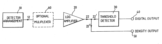
The apparatus, as shown in Figure 1,
comprises an infra-red densitometer detector
arrangement lO which is located close to the film
entrance (not shown) in a processing tank. The
detector arrangement lO operates both to project infra-
red radiation on to the film as it passes by it and to
detect radiation emanating from the film.
Any suitable infra-red source (not shown) may
be used. An infra-red sensor is mounted in the
detèctor arrangement lO for detectlng radiation
transmitted by the film.
An output signal 12 from the detec~or
arrangement 10 is then passed to a logarithmic
amplifie- 20 which amplifies the signal. A part 22' of -
the amplified signal 22 is then passed to a threshold
detector 30 which is connected to provide a digital
output signal at 40. The digital output signal is
~ produced when a change of infra-red density is
detected, for example as the infra-red opaque label
passes ~he detector arrangement 10, and is then used by
a computer ~not shown) to control film movement within
the processing apparatus.
Another part 22" of the amplified signal ~2
provides an output 50 which corresponds to the analogue
value of the infra-red density of the film.
If more than one film is to be processed
simultaneously, a separate infra-red detector
arrangement is required for each film. However,
although such a configuration of detector arrangements
gives the greatest flexibility, it also tends to be
costly to implement.
Alternatively, a multiplexer 60 may be used
to allow more than one film to be processed at the same
time. The use of the multiplexer 60 is optional and is
only required if the output signal from more than one
... . . .... . ... . ...
, - - - - - : :
. . . -, . . . ,, _
,
. -,;, ~ , . . -. , .-
W~92~ 2 ~ ~ 31~ 7 6 PCT/EP91/01728
densitometer detector arrangement 10 is to be amplified
by the same logarithmic amplifier/threshold detector
pair 20, 30.
If the output signals from more than one
densitometer detector arrangemen~ 10 is to be processed
by a single logarithmic amplifier/threshold detector
pair 20, 30, data from only one tank can be processed
at one time. However, by choosing a suitable
multiplexing rate and having sufficient computer power
and speed, all ~he process stages can be scanned
continuously. In this case, the data acquisi~ion rate
must be fast enough to catch the opaque label whenever
it passes the densitometer arrangement 10. In the
present case, a data acquisition rate of the order of
2ms is used.
Alternatively, the densitometer detector
arrangements may be grouped in twos or threes, each
group being multiplexed to a logarithmic
amplifier/threshold detector pair.
Each infra-red densitometer detector
arrangement 10 is used to measure the length of the
photographic film in the processing tank. As the ilm
is introduced into developer solution in the processing
tank, its infra-red density starts to rise. All the
time the film is in the developer solution, its infra-
red density is above a detection threshold. As the
film passes the densitometer head, a signal is
generated by the threshold detector 30 and indicates to
a control computer (not shown) that film is present.
After the film has made one circuit around the loop, a
second signal is generated. During this time, a
separate micro-controller (not shown) is readina and
processing the analogue infra-red density data.
The film is permitted to make two complete
passes of the loop to allow it to soften, and then the
:, ,
.. ... . . . . . ...................... .. .. . ..
.. . . . ..
. . . . _ . .
W092/0~72 ~ ~ 3 1~ 7 6 PCT/EP91/01728
film length and cycle time are measured. The cycie
time is measured between successive film edge
detections. The length of the total film path is fixed
and is therefore known. The time between detecting the
leading edge and the trailing edge of the film
represents the film length.
The film leng~h is given by:
t
10 , film length = ~ . d
tcycle
where tcyCle is the cycle time;
tfilm is the time for the film presence; and
15 d is the film path length.
This information is calculated by the
computer during the third pass and this value is then
used in relation to that particular film as it passes
through the rest of the processing apparatus.
The cycle time is continuously monitored for
each pass to cope with possible variations in film
transport speed.
The distance from the infra-red sensor to the
film switching point is fixed and is therefore known.
the computer calculates the switching time from data
stored in it ~hich is related to the time that the film'
first entered the processing solution, that is the
first detection in that processing solution. Using the
most recently acquired value of the cycle time, the
computer then calculates the precise moment at which to
operate the transfer or switching mechanism. The
algorithm used by the computer to do,this calculates
the switching time to the nearest half-cycle. This
gives an absolute accuracy in the processing time of
+/~ 5tcycle
- - - - - - - -
- W092/~7~ ~ B 915 7 ~ PCrtEP91/017
It may be advantageous to have the motor
speed of the drive system controlled by the computer.
This means that after the length of the film and the
cycle time have been measured, the computer can
calculate the motor speed required to give the precise
time in the most critical solution of the processing
cycle (namely, in the developer).
A time window may be used for the detection
of the leading edge of the film. Once the cycle ti~e
and the leng~h of the film have been measured, film
sensing is disabled until a few tenths of a second
before the leading edge is expected, based on the most
current value of cycle time~ This feature is
particularly important during fixing as the infra-red
density of the film gradually falls to zero. In this
period, high and low density infra-red density regions
on the film may c~use spurious detections. Window
detection as described above overcomes this problem.
It is important to note that at the end of
fixing and in subsequent processing solutions, only the
infra-red opaque label on the film will generate the
film position signal.
There are substantial advantages in using
infra-red densitometer arrangements for determinins
film position information, one of these being that no
mechanical parts are required. This keeps the film
track in the processing apparatus clear with less
likelihood of film jams. Another advantage is that
densitometer arrangements are already in use in some
processing tanks, and the same arrangement, in
conjunction with appropriate computer software, could
be used to determine the fi}m position thereby
providing a cost effective arrangemen~.
.. . . .. .. . . .. .
- - - - .
. .
, ~ ; ,~ - . :
. : . : :