Note: Descriptions are shown in the official language in which they were submitted.
~ U 9 ~
This invention relate~ to a procesa of coollng
hot granular solids under a pres3ure from 2 to 50 bars in 8
fluidlzed bed, whlch i9 disposed in a coollng chamber provided
with an inlet for solids and an outlet for solid~ and in which
the solids move mainly in a vertical direction from the inlet
for solids dispo3ed at one end of the fluldized bed through
the tluldized bed to the outlet for ~olld~ dl~po~ed at the
oppoalte eno of the fluldlzed bed, ~luldlzlng ga~es sre ln-
troduced lnto the lower portion of the fluidized bed and heat
i8 lndlrectly dlssipated by cooling means, ~hich are flown
through by a cooling ~luid and extend over at least one-half
of the height of the fluidized bed. The invention relates also
to an apparatus ~or carrying out that process. The coollng
mean~ may be disposed ln and/or surround the fluidized bed.
A process and an apparatus of that klnd, whlch are
gultable al90 for an operatlon under increased pressure, are
known from E~-A-0,407,730. It 19 an obJect of the inventlon
so to improve the process and the apparatus that the structu-
ral and operating costs are decisively reduced. It 18 parti-
cularly desired to effect an intense cooling of the eolids and
to reduce the demand for fluldizing gases.
5 ~
-- 2 --
In the process desc~bed first hereinbefore
the obJect ~ 5 accomplished ln accordance with the lnventlon
ln that the ~luldlzed bed has a bed height from 2 to 20 me-
ters, the ratio of the bed height ta the average bed wldth
19 between 2:1 and 10:1, the cooling fluid flo~s cocurrently
or countercurrently to the sol~ds movlng from the inlet for
solids to the outlet for solids, and the difference between
the temperatures of the ~olids in the lower and upper por-
tiongs of the fluidized bed is at least 80~0. The fluidizedbed is maintained under a superatmospheric pressure and i~
dlsposed in a tall and slender cooling chamber so that the
9paCe i9 effectlvely utlllzed and the demand for fluidlzlng
gaoes 19 low. ~eo~u~e the sollds are constralned to ~low ~rom
the lnlet through the Fluldized bed to the outlet, the ~avor-
able condltlons exlstlng ln the fluldlzed bed for the dlssl-
patlon of heat result ln the establishment of a distlnct tem-
perature profile ln the fluldized bed. The same fluidized
state 19 achieved as ln a statlonary fluldlzed bed.
Fluidized bed coolers which opsrate under atmos-
pheric conditlons or under pressures below 2 bars can be ope-
rated only with lo~ beds o~ing to a disturblng coalescence of
bubbles. The process in accordance ~ith the lnventlon ~9 car-
rled out under a pressure from 2 to 50 bars and preferably of
at least 5 bars and the bed bo~ a helght of at least 2 meters
and preferably of at lea~t 3 meter~ 90 that the b~se area un~
der the flu~dlzed bed and the demand for fluldizing gas are
minimized.
~ d ~
-- 3 --
In the process in accordance wlth the lnventlon
the ratlo of the bed helght to the average bed wldth i9 from
2:1 to 10:1 and preferably amounts to at least 3:1. The ave-
r~ge bed width is calculated aa the mean of the large~t and
smallest wldths measured on a horlzontal plane that extend~
through the fluldlzed bed, unle~s the croas-sectlon is clr-
cular. If the cross-~ectlon of the bed varles over the height
of ~he bed, the average bed wldth wlll be the mean of average
vslues of various bed cross-sectlons, which extend through
the fluidlzed bed on dlfferent levels spaced, e.g., 50 cm
spQrt.
In dependence on the locatlons of the lnlet for
sollds and the outlet for sollds the sollds to be cooled wlll
be constralned to rise or descend ln the fluidized bed and an
intense mixing of the solids ln the vertlcsl direction cannot
be expected 90 that the temperature of tne solids varies ac-
cording to a profile over the height of the bed. For thi3
resson the cooling fluid, which flows upwardly or downwardly
in lines of the cooling.means in the fluidized bed, may be
caused to flow consistently countercurrently or cocurrently
to the solids. Particularly during a countercurrent operation
this fact will result in a strong heat transfer from the so-
llda to the cooling fluid. Advantage~ will be afforded by a
cocurrent operatlon if it i9 desired to qulckly cool the ao-
llds immedlately after they have entered the fluldlzed bed or
lf the solids rise and it 19 deslred to evaporate the cooling
fluid.
.,
-- 4 --
The cooling fluid msy con~ist of a liquid or of
a fluld ln the form of a gas or vapor. Suitable known coDling
llqulds lnclude, e.g., water, oil9 or molten ~alts. The heat
moy alternatlvely be dls~ipated, e.g., by water vapor or by
various gaoes (such as nltrogen).
The hot sollds are supplied at temperatures from
about 300 to 1200C, u3ually at temperatures in the range from
400 to 1000~. In the fluidlzed bed formed ln accordance wlth
the lnventlon the dlfference between the temperatures of the
sollds ln the upper and lower portlons of the fluldlzed bed
may amount to 150C and more.
In the tall fluldlzed bed havlng a small cross-
sectlonal area which 19 provlded ln accord~nce wlth the in-
ventlon the dem~nd for fluldlzlng gases 19 relatlvely low.
300 to 750Q sm3 (sm~ standard cublc meter) o~ fluldlzing
gases per cublc meter of the fluldlzed bed volume snd per hour
wlll be sufflclent.
A dl t f th embodiment f th 1 tl
the hot sollds are lnltlally precooled ln a precedlng fluldlzed
bed dl~posed ln a precedlng aecond cooling chamber, ln whlch
the sollds move also from an lnlet for sollds at one end of
the second coollng chamber malnly ln a vertlcal dlrectlon
through the precedlng fluldlzed bed to an outlet for sollds at
the opposlte end of the second coollng chamber. Approxlmstely
the same pressure 19 maintalned ln the precedlng fluidlzing
chamber as in the succeedlng fluldlzed bed. In the precedlng
.. ,., , . . ., .. ,~ .. i.. - .! ... .... .
5 ~
fluldized bed, heat is also indlrectly dissipated by caoling
mesnsf which are flown through by a cooling fluld and whlch
extend over at least one-half 1~ the height o~ the preceding
fluidized bed. The bed height of the preceding fluidized bed
19 ln the range from 2 to 20 meters ~nd preferably amounts to
st least 3 meters. The ratio of the bed helght to the average
bed width of the precedlng fluidized bed is from 2:1 to 10:1
and preferably amaunts to at least 3:1. In the preceding flui-
dlzed hed the cooling fluld i9 al90 caused to flow cocurrently
or countercurrently to the solids moving from the inlet for
solids to the outlet for solids, and the difference between
the temperstures in the lower and upper partions of the pre-
ceding fluidized bed is at le0~t ~0C and prefersbly ln excess
of 200C. The solids which hcve been precooled in the preced-
lng fluidized bed move from the outlet for slids directly to
the lnlet for sollds assoclated wtih the succeedlng fluidized
bed, in which the cooling i9 continued.
The salids preferably movedgwtwerednYthe 1 1 t f
sollds and the outlet for sollds in the preceding fluidized
bed and rise during the contlnued cooling ln the succeedlng
fluldlzed bed to the outlet for sollds assoclated wlth the
fluidized bed.
The inventlon provldes also to an apparatua for
cooling hot granular solids under a pressure from 2 to 50 bars
ln a cooling chamber, whlch contalnR a fluidlzed bed formed
by the solids and i9 provided with an inlet for solids and an
outlet for sollds and contains cooling means for indlrectly
cooling the solid~ and i9 provided in its lower portion with
means for supplying fluidizing gases. The cooling chamber i9
de31gned to accommodate a fluldized bed having a bed height
from 2 to Z0 meters and a ratlo of the bed height to the
average bed width ~rom 2:1 to 10:1.
embodiment
A ~urther of so~d cooling spparatus re-
sides in that the cooling chamber (first coollng chamber) i8
preceded by a second cooling chamber, which has an inlet for
aolids and an outlet ~or sollds, whlch iB cannected to the
inlet for sollds associated with the fIrst cooling chamber.
Embodiments of the process and appa-
ratus will be explained with reference to the drswing, in
which
Figure 1 is a schematlc longltudinal sectional
view showing a first cooling apparatus,
Figure Z is a longitudinal sectlonal view showlng
a second coallng apparatus,
Figure 3 is a graph lndlcatlng the demand for
fluldlzlng gas, and
Figure 4 19 a longitudlnal sectlonal vlew showlng
a known fluldlzed bed cooler.
The apparatus shown ln Flgure 1 comprlses a tall
and slender cooling chamber 1, whlch is provided with an ln-
let 2 for solids and an outlet 3 ~or solids. During operation
the cooling chamber 1 contalns a fluidized bed, not shown,
which conslsts of granular solids, which are cupplled through
llne 4. The flui~i~ed bed extends from a nozzle grate 5 to
the outlet 3 and surrounds the helical line of cooling means
6, through whlch a cooling fluid for dlssipatlng heat 19 con-
ducted. Fluldlzlng gas i~ supplled through line 8 ~nd flrat
enters a dlstributlng chamber 9 and then rlse~ through the
nozzle grate 5 0nd fluidizes the ~uidlzed bed. The fluidiz-
ing gases which hsve left the fluidized bed first flow inbo
an enlarged stllllng space 10 and then lea~e the coollng appa-
ratus through an outlet 11, which may be connected to mesns
for a further processing, which ~re not shown and may consist,
e.g., of dedustlng means.
The cooling chamber 1 i9 80 de3igned that the
fluldlzed bed contained ln the chamber has a height from 2 to
20 meters and preferably of at least 3 meter~. Under the ac-
tion of the fluidlzing 939, such as alr, the granulQr sollds
to be cooled rlse in the coollng chamber 1 from the inlet 2
for sollds and leave the fluidlzed bed through the outlet 3.
Owing to that predetermined movement o~ the sollda the coollng
fluld can be conducted ln the cooling means 6 cocurrently or
countercurrently to the sollds. The rate at which solids enter
the fluidized bed may be controlled by a gas which is fed
through a llne 13 to the lnlet 2. The coollng chamber 1 and
the stllling space 10 are enclosed by a pressure-reslstant
vessel 12.
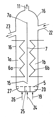
The coollng apparatus ehown in Figure 2 comprises
a flrst coollng chamber 1a and a second coollng chamber 1b.
~ partitlon 7 is dlsposed between the coollng chambers 1a and
,: : . - :,,, ,: . - - . ,
1b, and an openlng 15 i9 left between the nozzle grate 5
and the bottom edge of the partition 7. The cooling chambers
are enclosed by a ~ressure-resistant houslng 16, whlch i9
provlded wlth an lnlet 22 for solids snd an outlet 23 ~or
sollds. The top edge 7a of the partltlan 7 i9 dlsposed above
the inlet 22 and the outlet Z3. Fluidizing gases leave the
houslng through the outlet 11.
Hot ~olids are supplied through the inlet 22 and
initially enter the second cooling chamber 1b, which contains
a fluidlzed bed, which i9 deacribed here as the "preceding
fluidized bed". Fluidizing gas for the preceding fluldized bed
is supplieo through line 19 and enters the distributing cham-
ber 20 and then rises through the second cooling chamber 1b
to the outlet 11. The solids descend in the precedlng fluidized
bed in the second cooling chamber 1b and through the openlng
15 enter the fluldlzed bed ln the fir~t cooling chamber 1a.
The space which i9 constltuted by the opening 15 ls supplied
wlth fluldizing gas through a line 24 and a dlstributlng cham-
ber Z5, which i~ disposed under the nozzle grate 5. The rate
at which sollds mo~e through the openlng 15 can be influenced
by a change of the rate at which gas ls supplled through line
24. In that way the rate at whlch solids are supplied to the
flrst cooling chamber 1a can be controlled by a fluld-dynamic
valve.
The opening 15 serves a~ an inlet for ~o~ds en-
tering the fluidized bed in the first cooling chamber 1a, in
which the sollds rise in a stationary fluidized bed until they
,: . . ' . :: . .: . ' -' :: ' . . , ~: ;, : , ~ , ;!, :, : ~ : :
' ~ ' ' . . . ' . ' ' : . ' . . . ::: . , ' ' . : .: . ' ': : - "
5 ~
lea~e the cooling apparatus thrcugh the uutlet 23. Fluidlz-
lng gas 19 supplled through llne 26 and throuqh the dlstri-
buting chamber 27 and the grate 5 enters the fluldlzed bed.
The arrangement shown in Flgure 2 may be modlfied in that the
two coollng chambers 1a and 1b are arranged in a hnusing which
i8 not de~igned to wlthstnnd a relatively high pre~sure and
which la disposed ln a separate pressure housing as shown ln
Figure 1.
The remarks made hereinbefore in connection wlth
a single fluidized bed regarding the bed height, the ratio
of the bed height to the average bed width and the dlfference
between the temperatures in the lower and upper portlons of
a fluldlzed bed are appllcable to the flrst cooling chamber 1a,
the second coollng chamber 1b, and the ~luldized beds con-
talned thereln. It la apparent thst the sollds snd the cool-
lng fluld may be conducted cocurrently or countercurrently in
the precedlng fluldlzed bed and ln the succeedlng fluidized
bed and the coollng fluid flo~s through the cooling means 6a
and 6b.
In numerous applications the veloclties of the
fluidizinq gas lie in the range ~rom O.Z to 0.~ meters per -
second and may be regarded as belng substantially lndependent
o~ pres~ure.
In the graph shown as Figure 3 the ascertained
dependence of the demand V for fluidizing gas (ln sm~ per hour
and per cubic meter of fluidized bed volume) on the pres~ure p
.. , , , . , .. ~ ~ .: , :
- ~, , . . . . . .- ., ": , ,.,. : , ~: :
- ; . j: :- :. . ~ , -
... . . .. . ...
i6~
-10-
19 represented for vsrious bed heights h (h = 1, 2, 5, 10
and 20 meters) far a fluldlzing gss ~lowing at a velocity of
0.5 meter per second and a temperature of 500C and particle
slze~ of the solids from 100 to 400 mlcrometers in the flul-
dized bed. It is apparent, e.g., from the point A that
V = 6500 will be required at p = 10 b~rs and a height h = 1
meter whereas V = approximately 1300 will be ~ufficient if
the pressure is the same and the bed height h is 5 meters
(point E).
Compa~ative . Example
In the partly calculsted comparison described
herelnafter a conventlonal known flat fluldized bed cooler,
tall
as shown in Figure 4, is compared with a fluldized bed cooler
as shown in Figure 1. The ~luidlzed oed cooler shown in Fi-
gure 4 comprl~e5 o housing 30 provlded with an inlet 31 for
sollds, an outlet 32 for so~ds and a sys~em 33 for fluidizing
gases and 19 divlded by three welrlike partitlons 34 lnto
four chambers 35, 36, 37 and 3B. Each chamber contalns a flui-
dized bed, and the sollds move from the inlet 31 over the partitions
34 and through the fluldlzed beds to the outlet 32. Each
fluidized bed is indlrectly cooled by coollng means 39, whlch
are supplied with cooling water. Fluidizing gasea are wlth-
drawn ir line 40.
In the P example each chamber of the sppa-
ratus shown ln Figure 4 has a horizontal cross-sectional are~
of O.BB m2 and the fluidized bed shown in Figure 1 has also a~
; r ~ "
horizontal cross-sectional area of 0.88 m2: Further datn are
apparent form the following Table.
'.!i Figure 4 Figure_1
Height of ~luidi~ed bed 0;5 m 2.0 m
Total fluidlzed bed volume 1.76 m3 1.76 m~
Surface area of cooling mean~ 36 m2 36 m2
Presaure 10 bars 10 bars
Solids rate 2500 kg/h 2500 kg/h
Cooling water rste ~000 kg/h 8000 kg/h
Fluidlzlng gas rate 4B,000 kg/h 12,000 kg/h
Temperatures
Solids at lnlet 700C 700C
Solids at outlet 126C 123C
Coollng wster at lnlet 30C 30~C
~oollng water at outlet 9ZC 9~C
Fluidlzlng gas at lnlet 150C 150C
Fluldlzlng gas at outlet 146C 123C
The data have been calculated ln part and
sre based on ~olid~ which conslst o~ coal ash and have par-
ticle sizea ln the range from 0.1 to 1 mm. Air ia ueed as a
fluidlzlng gas and i8 conducted through the fluidized beds ln
all case~ at a velocity of 0.4 to 0.7 meters per second.
It i~ apparent from the Table that for a glven
fluidlzed bed volume, given cooling means, a given cooling
water rate and a glven veloclty of the ~uidizlng gaa the tall
Pluidlzed bed of Figure 1 require~ only one-fourth of the rate
. ~. ;. , , . - , - , .. . . " ,,, ~, ", . :
5 ~
-12-
of ~luldizlng gag that i~ requlred ln the apparatus shown
ln Flgure 4 and the structural expendlture ls lower. The ln-
Pluence of dead corners, whlch by experience are ~ound in
~lat fluldized bed coolers as shown ln Flgure 4 and addltlo-
nally reduce thelr efficlency have not been taken into ac-
count ln the calculatlons.