Note: Descriptions are shown in the official language in which they were submitted.
2~ ~ 7~
DISPO5ABLE RES~RVOIR
Field o~ ny~iQn
This invention relates to covered reservoirs
as are used in, e.g., clinical analyzers to provide
liquids needed, for example, reference laqui~s.
~s~LrQund o~ ~he Invention
Reference liquids are used in many clinical
analyzers to conduct potentiometric tests uQing twin
ion-selective alectrodes. One of those electrodes is
contacted with the patient sample having an ion of
unknown concentration, and the other electrode is
contacted with the reference liquid having a known
concentration of ions. Mo~t preferably, such ions are
highly concentrated to the point of near saturat.ion,
for the reason that the junction potential between the
reference liquid and the sample need~ to be deminated
by the reference liquid concentration, which means the
latter must be highly concentrated. The reference
liquld is qtored in a reservoir that has to be
replenished. See, e.g., U.S. Pat. No. 4,740,274 for
further details on the reference liquid.
For years the most common reservoir ~or such
a refexence liquid has been a ylass or plastic vial
that is capped with a rubber seal that is machine-
opened and closed. Before the vial is replenished, ithas to be removed and cleaned to maintain an accurate
concentration of the ion~ Such a procedure has been a
problem because it is time-consuming, labor intensive,
and if not done properly, introduces errors due to the
concentration of the liquid being altered.
There has therefore been a long-standing need
for a disposable, single-use reservoir which, although
preventing evaporation, readily allows access to the
liquid by an aspirator. "Single-use" as used here
means used until the liquid contents of the reservoir
have been exhausted without replenishment.
2 ~ 7 3 ~
--2--
The most obvious solution to the need was to
form the re~ervoir as a qimple plastic body with an
aperture at the top sized to seal on the aspirator when
it is insarted. In that fashion, the aspirator acts as
a stopper when it is kept in the reservoir ~perture
when no re~erence liquid is ~eing dispensed in the
analyzer. ~owe~er, it was soon discovered that this
design was unsatis~actory beca~se insertion o~ the
a~pirator into its sealing position created severe
pumping action in the reservoir due to flexing of the
top of the reservoir that interfered with pressure
sensing that is otherwise necessary with such
aspirators.
The next step was to enlarge slightly the
aperture for the aspirator, so that a complete sealt
~nd hence pumping, did not occur due to the "leak"
created. The aperture could not be made too large,
however, as evaporation then i9 too substantial.
However, this was found to be a failure in that the
"leak" portion of the aperture created a ~ufficient
capillary path for liquid when it sloshed, as to cause
unacceptable crusting of the high salts contents of the
liquid at that "leak" portion.
Next, a flat cover, apertured for the
aspirator, was designed to fit over and close off the
top of ~he reservoir. However, this sealed to the top
of the reservoir along a flat surface. The flat cover
attempted to achieve controlled venting by a long
diffusion path between the cover and reservoir.
However, economical manufacturing tolerances would not
allow the gap to be controllad tightly enough to
prevent excessive evaporation in worst case conditions.
~ hus, for many months, attempts have been
made to create an acceptable disposable alternative for
the permanent glass reference liquid reservoir
heretofore used, all without success.
~9173~
3--
Summary of the Invention
I have designed a disposable reservoir with a
cover that finally solves the problems noted above.
More specifically, there is provided a
covered reservoir for providing liquid to a pipette
through an opening, the reservoir compris:ing a body for
holding the liquid in bulk, the body t:erm:inati~g in a
upper, generally flat rim extending out over a portion
the body and a~ aperture le~t open by the rim; a cover
having an aperture therein for accessing the li~uid
with a pipette and a contact surface for contacting the
rim; a seal disposed between the cover and the body to
restrict evaporation, and means for biasing the cover
against the seal and the body. The cover further
includes a) a generally planar recess adjacant to the
cover contact surface of a size and shape e~fective to
receive the seal between the cover and the rim without
clamping it, b) a shoulder depending from the recass
and surroundir,g the aperture and around which the seal
is mounted, the shoulder having an outside diameter
sufficient to friction fit it with the annular ring
seal, and c) raising means joining the shoulder to the
recess and surrounding the shoulder, for raising the
annular ring seal from the recess into a frusto-conical
position sufficient to cause said rim at the rim
aperture to press into the annular ring seal ~hen the
cover contacts the rim.
Accordingly, it is an advantageous feature of
the invention that a cover is provided for a disposable
reservoir for pipette access, that seals against the
reservoir body in a manner that reduces evaporation
while at the same time preventing "pumping" and ~alt
formation due to liquid contact.
Another advantageous feature of the invention
is that the parts of the cover are readily removable
for cleaning.
2 ~ 3 8
,~.
Other advantageous features will hecome
apparent with reference to the following detailed
description, when read in light of the attached
drawings.
Brie~ Descri~tion of the Drawings
Fig. 1 i~ an elevakional view of a reservoir
constructed in accordance with the invention, the
phantom lines illustrating the cover in its open
positionj
Fig. 2 is a plan view of the reservoir;
Fig. 3 is a section view taken generally
along the line III-III of Fiy. 2;
Fig. 4 is an enlarged fragmentary section
view of the portion of Fig. 3 marked as "IV"; and
Fig. 5 is an elevational view similax to that
of Fig. 1 but showing the cover raised to its open
position, and the cover being rsmoved in phantom.
~escri~tion o~ the Preferr~d_~mbss~ n~a
The following description relates to the
invention in itQ preferred embodiment, wherein a
saturated salt ~olution ls contained in a disposable
reservoir container, using a cover removably held on a
retainer that is bi-stably and pivotally mounted onto
the ~rame holding the container with a spring that
tends to bias the cover closed. In addition, the
invention is useful regardless of the liquid held in
the resexvoir, whether it is disposable or not, and
regardless of how the cover is retained on the
reservoir, so long as it has the seal features of the
invention.
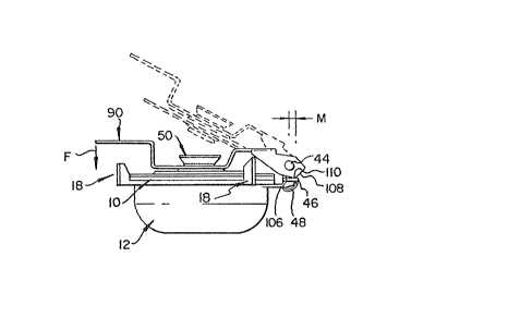
A covered reservoir constructed in accordance
with the invention is illustrated in Figs. 1-3.
Generally it comprises a reservoir body 10, a cover 50,
a cover retainer 90 and a seal 120, Fig. 3. The
reservoir body 10 is preferably disposable, and sits in
a housing or holder 12 shaped as a bowl, the bowl
2 ~ 3 8
preferably having a shape that complements the shape of
the reservoir body 10, as shown most clearly in Fig. 3.
Thusl bowl 12 has a closed bottom wall 14 and an upper
lip 16 extending preferably around its circumference,
and can optionally include fastening Elanges (not
shown) for securing the lip and bowl to a clinical
analyzer. Guide fingers 18 project upwardly from lip
16, with a guiding surface ~0 sloped to center the
cover when it is lowered, as explained ~elow.
Reservoir 10 compri~es body wall 30 that
terminateo in an upper lip 32 shaped to rest on lip
16, and a generally flat rim 39 that is sealed to the
lip 32 and extends out over body wall 30 except for an
access aperture 36 shaped to receive a center portion
of the cover 50 o~ the reservoir and an aspirator t;ip
"T" inserted therein. ~xterior surface 38 o~ rim 34
comprises the contact surface for contact with the
cover, a~ explained hereinafter.
To help retain cover 50, pivot lugs 40 are
preferably included, Fig. 2, as part of the molded
shape o~ bowl 12 at the back side. Specifically, Fig.
3, lugs 40 each include aperture 42 through which a
pivot pin 44 extends, and ears 46 and 47 extending
horizontally from lugs 40. Ears 46 act as supports for
2~ the bi-stable camming of ~he retainer, described below,
and ear 47 is the anchor for a ~pring 48 that biases
retainer 90 closed when the latter is properly pivoted.
Apertures 42 are larger than the diameter of
pin 44, to allow the pin to raise and lower with the
pivoting action of retainer 90.
Most preferably, spring 48 is a tension
spring with a spring constant sufficient to provide no
more than about 60 g (1/8 pounds) of spring ~orce
downwardly on retainer 90 at end 94, Fig. 3, a~ shown
by force "F". Any spring *orce significantly greater
than that will tend to cause splashing of the liquid,
~3:17~
which in turn can cause loss of liquid or crusting of
the cov~r. Also, it would cause a "snap" that can
startle the operator working inside the analy~ar.
Cover 50 comprises preferably a ~airly rigid
disk the outer circumference of which is a generally
flat flange 52 having a bottom contact surface 54 for
contacting rim 34. The disk is preferably symmetric
about a center axis 56. Inside of and adjacent to
flange 52, closer to axis 56, is a generally planar
annular recess portion 58, the depth d of the recess
measured from surface 54 to surface 59 of portion 58,
Fig. 4, being more than the thickness of seal 100,
described below. Still further in towards axis 56 is a
shoulder 60 that extends out of the p:lane of flange 52
and recess portion 58, preferably in both directions,
which shoulder in turn surrounds an access and aperture
70 on axis 56, into which tip T is inserted, Fig. 3.
Shoulder 60 comprises a lower portion 72 and
an upper portion 80. Lower portion 72 has an outside
diameter that cooperates with seal 100 to friction it
the seal around the shoulder, Fig. 4, and is integrally
joined to surface 59 of recessed portion 58 by a
frusto-conical surface 74 that extends entirely around
axis 56. Surface 74 is shaped to space or raise seal
100 off surface 59. To that end, the height of surface
74, measured along axis 56, is generally equal to depth
"d".
Additionally, lower portion 72 includes means
for inducing condensed vapor to flow back into
reservoir body 10, rather than to evaporate out
aperture 70. Specifically, Fig. 3, a flange 76 extends
out from lower portion 72 towards axis 56, to form a
seat for pipette tip T. Where flange 76 joins portion
72, its bottom surface is sloped downwardly at 78 to
provide a run-off surface for condensation.
2 ~ 7 3 ~
Upper portion 80 of shoulder 60 includes a
raised boss 82 used to help seat retainer 90, discus~ed
below,at the correct height, and an engaging flange 84
designed to slip through ~lot 98 of retailer 90, Fig.
2, th~s holding cover 50 within the r~etainer.
Conventional rigid pla~tics are preferably
used to mold co~er 50. To provide sufficient rigidity,
the thickness of recessed portion 58, Fig 3, can be,
for example, about 1.5 mm.
To removably hold the cover 50 onto reservoir
body 10, a retainer 90 is hingedly ~ounted on pin 44 at
retainer end 92, Fig. 3. Opposite end 94 is a handle
portion, bent upward at portion 96 to form an L-shape
for easier grasping. Portion 96 is slotted at 98, as
best shown in Fig. 2, slot 98 being na~rowad at 100 on
portion 102 of retainar 90 that s.its on boss 82, so as
to lock in engaging flange 84 when cover 50 is slid to
the rear of retainer 90.
~nd 92 o~ retainer 90 provides the bi stable
~0 position~ng of retainer 90, in cooperation with ear~ 46
and spring ~B. Speci~ically, end 92 is provided with
two cam~ing surfaces 106 and 108, Fig. 1, that contact
ears 46 alternately, as end 92 is pivoted on pin 44
about its pivot point 110 between surfaces 106 and :L08.
Seal 120, Figs. 3 and 4, is preferably an
annular seal of flexible material, such as rubber or
synthetic plastics. Whatever the material, it is
preferably at least as elastic and flexible as a
silicone rubber having a 30 Shore A Durometer value.
The inside diameter 122, Fig. 4, is such as provides a
friction fit of the seal over shoulder 60 and
specifically causes it to rest at edge 12~ of surface
74. The thickness "d1" of the seal is ~ufficiently
less than dimension "dl', that is, by amount g", such
that when cover 50 closes into contact with reservoir
body 10, the contact is via flange 52 on surface 38,
2 0 9 :I r
--8--
and outside diameter 126 of seal 120 is not clzmped
bPtwean surface 59 and Qurface 38. (For example, "d1"
can be about 0.8mm and recess depth 'Id" can be about
1.3 mm.) Because of the rigidity of the plastic of
flange 52 and recessed portion 58, this ensures that
the force of pipette tip T contacting qhoulder 60 is
absorbed by cover flange 52l thus minimizing or
eliminating any pumping action, due to the rigidity of
the cover. Comparatively, i~ seal 120 had a thickness
"d1" that equals or exceeds gap "d", then the contact
force of tip T would be transmitted at seal 120, the
moment arm of flange of 52 would be inefEective to
absorb that shock, and "pumping" would likely occur.
The softness and/or flexibility of seal 120,
as well as its raised frusto-conical position on th~
edge 124 of surface 74, Fig. 4, ensuro that, upon
closure of cover 50 onto reservoir body 10, apertur~3
edge 36 o rim 34, pushes into seal 120, around the
entire circumference of shoulder 60, thu~ sealing off
what would otherwise be an evaporation path out between
Qurfaces 38 and 59.
The reservoir cover's use and functions will
be readily apparent from the previous description.
Briefly, cov~r 50 is removed and replaced, arrow 200,
Fig. 5, by sliding ~houlder 60 and flange 84 out ancL in
through slot 98, respactively, Fig. 3. Once in place
in retainer 90, the retainer is pivoted, Fig. 1, arrow
220, by ~rasping handle portion 94. This causes encl
portion 92 to pivot about point 110, raising retainer
90 slightly, until the point 110 passes behind vertical
line 230 of pivot pin 44. At this point, spring 48,
Fig. 3, is effective to pull the retainer and cover
shut, with surface 106, Fig. 1, resting or almoQt
resting on ear 46 and seal 120 closing off aperture 36,
Fig. 4. Fars 18, Figs. 1 and 2, are effective to
properly guide and center cover 50 as it closes onto
7 3 ~
raservoir body 10. The spring action of sprin~ 48,
Fig. 3, acts through moment arm "~ , Fig. 1, to delivar
closure force F, Figs. 1 and 3, on handle portion 9
(discussed above).
Although it is true that aperture 70 becomes
a leak path when tip T is removed, this path occurs
only temporarily, during dispensing of the liquid, and
thus is not as much of a leakage compared to any path
between sux*aces 38 and 59 that is uD~locked by seal
120.
The in~ention disclosed herein may be
practiced in the absence of any element which is not
specifically disclosed herein.
The invention has been described in detail
lS with particular reference to certain preferred
embodiments thereo~, but it will be understood that
variation~ and modifications can be ef~acted within the
spirit and scope of the invention.