Note: Descriptions are shown in the official language in which they were submitted.
20~19~5
PO:~TABLE HAND-~:LD POWER ASSISl~;~ DEVICE
BACKGRQ~D QF THE lNVENTiO~
1. Field ofthe Invention
This invention relates to a hand-held controllable power assister
device as applied to syringes adopted to deliver a liquid into a patient.
10 More particularly, the invention relates to a held-held controllable power
injection device for delivering, by injection, x-ray contrast media into a
patient prior to or during urographic or angiographic procedures.
2. Re~orted Develo~ments
1 5
Urography is a radiological technique wherein at least a part of
the urinary tract OI a mammal is rendered opaque by intravenous
injection of a contrast medium or by injection into the bladder through
the urethra.
Angiography is also a radiological technique wherein the arteries
or veins of a mammal are outlined by injecting a radiographic medium.
In both techniques the coated vascular structures are
2 5 radiographically imaged for diagnostic purposes.
For delivery to the desired site, the contrast medium is placed in
an appropriate syringe and forced through a hollow needle or a catheter
in such a manner that the contrast medium enters the blood stream or
3 0 the bladder at the appropriate time and place for taking radiographic
images. As contrast medium is being injected to the site to be visualized
through the hollow needle or a catheter, high pressures are often
encountered, sometimes as high as 1,000 psi. This requires a rather
high force to be exerted on the piston in order to deliver the content of the
3 5 syringe. Furthermore, such force is to be exerted in a constant manner
- 20~19~
for continuous and even volume delivery of the contrast medium. Early
injection systems were designed for manual injection of the contrast
medium by means of a hand-held glass syringe. A mechanical injection
system activated by a foot s vitch has also been, and is still being used for
S most general radiographic procedures. However, this system was only
rarely used for coronary angiography for the probable reason that
operator control is greatly reduced and the risk of coronary artery
dissection increased.
Power injectors in general have certain advantages over hand-
operated injectors including the following. They reduce reliance on an
assistant enabling the operator to be in complete control of the injection
of the contrast medium, they can deliver a precise volume, and the
pressure generated can be limited by presetting a pressure limit.
1 5
Power injectors are of three types: hydraulic, pneumatic and
electric. Hydraulic injectors have an electric motor connected to a
hydraulic pump, which drives a ram connected to a syringe that
contains the contrast medium. In pneumatic injectors, the source of
2 0 power is compressed gas supplied by a tank or compressor. Electric
injectors are powered by electric motors in which a transmission means
serves to change circular motion into linear motion which then drives a
ram.
2 5 While typical power injectors eliminate the physical effort
required with manual injectors, they are not easy to use, are expensive
and the perception of instantaneous control present with manual
injectors is lost because the syringe and controls for the injectors are not
hand-held or not conveniently handleable during the injection process.
3 0 For example, a gas power-assister hand-held syringe does eliminate the
physical effort associated with manual injection and also provides a
perceived instantaneous control of the injection, however, it requires a
gas system to power the syringe, such as pressurized carbon dioxide
gas. The gas delivery system includes a carbon dioxide gas tank with
.
` 20919~
various indicators and controls, which reduces the portability of the
device, it requires valuable space in the proximity of the injection, it adds
to the complexity of using the device for the intended purpose and
requires periodic replacement of the gas tank.
Battery pow,~ered injectors are also available for use in
angiography and urography employing a syringe for holding a contrast
medium and a plunger connected to a mechanical means to
automatically deliver the contrast medium. Some of these injectors
10 include microprocessor technology for programming rates and time
delivery and have visual or audio display for ease of controlling the
injection process. As these injectors become more 60phisticated, the cost
of making and using them increases as well as the complexity of use
tends to increase the opportunities for breakdown.
The present invention is directed to a hand-held, light-weight
power assister which eliminates the physical effort required with
manual injectors but otherwise allows the practitioner complete human
control of the injection process.
.,
.
:,
.
. , -, . .
:; . . .
.~
4 209194~
26299-48
SUMMARY OF THE INVENTION
The power assister device of the present invention is
designed to be hand-held by one hand, light weight, inexpensive
and to allow complete control over the process of delivering
radiopaque media to the patient by the medical practitioner.
To that end, its configuration resembles a pistol, the handle
portion of which provides for firm hold. Activating switch,
having on-off- and neutral positions, is located in the handle
portion to be controlled by the index finger of the practitioner.
While the device does not incorporate complicated and expensive
electronic components which tend to break down and are cumber-
some to use, it provides electrical energy to deliver the
contrast media to the patient at a constant rate of delivery
and it incorporates limit switches to automatically stop the
electric motor when the lead screw, which engages the piston, is
in its initial or completely extended position.
In accordance with the invention, the hand-held power
assister device comprises: a pistol-shaped casing; a syringe
having a slideable piston therein, removably coupled to said
casing; and drive means, contained in said casing, for driving
the piston in said syringe to deliver said liquid to the patient.
The casing is preferably made of light but tough
plastic material and safely houses all components which may
include: a D.C. motor to provide angular motion; rechargeable
batteries to supply electrical power to the motor;recharging means
for the batteries; a lead screw having a female engagement means
to engage a piston; gear means to translate angular motion
209194S
4a
26299-48
produced by the motor to linear motion of the lead screw;limit
switches to stop the motor when lead screw is in its initial
or completely extended positions; and
20919~5
trigger switch with electrical leads to batteries and to the motor
for controlling the movement of the lead screw.
The syringe used in the present invention may be of various sizes,
such as from 10 ml to 50 ml to 100 ml or larger, depending on the volume
requirement of the patient and the type and concentration of the
radiopaque or other media. The syringe has a luer connector at one end
to engage a catheter or a butterfly needle which is to be inserted in the
injection site. The other end of the syringe is equipped with a flange to
engage a receiving slot in the front end of the casing of the hand-held
power assister device. The syringe barrel holds a slideable piston or
plunger therein and is equipped with a male engagement means to
mate with female engagement means of the lead screw.
The recharging means consists of a recharger unit equipped with
two plugs one of which is inserted into the receptacle on the power
assister device and the other into a standard electrical outlet.
20919~
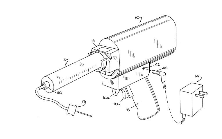
FIG. 1 is a perspective view of the hand-held power assister, a syringe
S engaged with said power assister, butterfly needle in place and
battery charger unit;
FIG 2. is a fiectional view of the hand-held power assister;
FIG.3 is a cross-sectional view of the hand-held power assister taken
along the line 3-3 of FIG. 2, showing the syringe engaged and
the syringe piston in its engagement position.
FIG. 4 is a cross-sectional view of the hand-held power assister,
1 5 showing syringe piston in its extended position, taken along line 3-3 of FIG. 2;
FIG.5 i6 a transverse cross-sectional view of the hand-held power
assister and syringe engaged therewith, taken along line 5-5 of
FIG.2;
FIG.6 is a partial transverse cross-sectional view of the hand-held
assister device taken along line 5-5 of FIG. 2;
S FIG. 7 is a cross-sectional view of the hand-held power assister taken
along the line 7-7 of FIG. 2;
FIG.8 is a cross-sectional view of the hand-held power assister taken
along the line 8-8 of FIG. 2; and
FIG.9 is a perspective view of the syringe not engaged with the power
assister.
20919~5
RIPIION ~ THE E~IBO12~T
Referring to FIG. 1, power assister device 10 is shown with
syringe 12 engaging said device, butterfly needle 13 attached to said
5 syringe by luer connector 50 and battery recharger 14 i6 ready to engage
power as6i6ter device 10 by insertion of plug 44 into receptacle 42.
When assembled together, power as6ister device 10 and syringe
12, along with handle 18 and trigger 20a-20b, resemble a pistol. This
10 configuration provides for firm hold control and convenient
handleability. The power assister device 10 comprises a casing which
serves as a housing and chassis for the components contained therein.
Referring to syringe 12, as shown in FIGS. 1, 2, 3 and 9, it
15 comprises: a syringe barrel to receive an injectable agent therein, said
syringe barrel having a luer connector 50 at one end thereof serving as
means for attaching butterfly needle 13 thereto, and the other end of said
tubular body having male coupling 46 to engage female coupling 38.
Flange 52 of syringe 12 locates and fixes syringe within a complimentary
2 0 slot (not shown) in front 16 of the power assister device 10. Loading of
syringe 12 is exceptionally easy and practical, since the syringe is drop-
loaded onto said slot without the need of any twisting or turning motion.
Positioned in said syringe barrel in a slideable relationship is piston 48
integral with male coupling 46.
As best seen in FIGS. 2, 3, 7 and 8, the casing or housing of the
power assister device 10 houses a D.C. motor 22 which produces angular
rotation of gear 24. Gear 24 drives gear 26 which has internal thread 28.
Linear movement of lead screw 30 is produced by preventing its rotation
3 0 and by the angular rotation of internal thread 28. A follower 32, fixed to
the back end of lead screw 30, prevents rotation of the lead screw during
linear movement by the engagement of peg 32a of the follower 32 rolling
or sliding in slot 32 b.
20919~ i
D. C. motor 22 is powered by rechargeable batteries 40, which are
located in handle 18 of power assister device 10. Trigger switch 20 a - 20
b engageably coupled to batteries 40 and D.C. motor 22 has three
positions: forward drive, reverse drive and off position. Forward limit
S switch 36 is positioned so that lead screw follower 32 triggers the switch
and stops the motor when piston 48 is in its extended position as shown
in FIG. 4. Likewise, the backwards limit switch 34 is positioned so that
the lead screw follower 32 triggers the switch and stops the motor 22
when piston 48 is in its engagement position as shown in FIG. 3.
The power assister device 10 is recharged by plugging recharger
14 in a standard electrical outlet and inserting plug 44 into receptacle 42
- during periods in which the device is not in use.
l S Reference is now made to the operation of the hand-held power
assister. The syringe 12 could be prefilled with an injectable liquid, such
as contrast media, or the power assister device 10 could be used to fill the
syringe. If not prefilled, the empty syringe 12 is loaded onto the front 16
of the device, having male coupling 46 engage female couple 38, then
j 2 0 placing the power assister device 10 in an upright position by placing it
.1 with is flat surface 9 on top of a flat object, such as a table. The syringe
12 is then filled with contrast media by first driving the piston 48 to its
extended position within the syringe as shown in FIG. 4. A plastic tube
(not shown) is attached to luer connector 50 and the contrast media is
2 S syphoned into the syringe 12 by placing the opposite end of the plastic
tube in a container filled with contrast media and retracting piston 48
back into its engagement position. Upon completion of the process the
plastic tube is removed from the luer connector 50 and a butterfly needle
13 is attached thereto. After butterfly needle 13 is attached to luer
connector ~0, the upright position of power assister device 10 is
maintained until the air from syringe 12 and butterfly needle 13 is
purged by driving piston 48 in the forward direction. To drive piston 48
forward or in reverse trigger switch 20a - 20b is provided. Trigger
switch 20a - 20b is positioned in handle 18 of the power assister device 10
.. .. .
- : `: ' .: ,,
, ... .
209~94~
to control both the forward and reverse motion of the piston: pressing - "
~Ob results in forward motion of piston 48, while pressing 20a results in
reverse motion thereof. When neither 20a nor 20b trigger switch is r
pressed, switch automatically reverts to neutral or off position and
motor 22 becomes disengaged.
In the case when the syringe 12 is prefilled with contrast media,
the syringe is loaded in the same manner as above-described, then the
power assister 10 is positioned in an upright position. Syringe cap (not
l O shown) is removed from luer connector ~0 and butterfly needle 13 is
attached to luer connector 50. The air is then purged from the syringe
as above-described.
Upon purging the air from syringe 12, the power assister device 10
l 5 is held by the medical practitioner at handle 18 with index finger resting
on trigger switch 20a - 20b which is in the off position. Protective sheath
(not shown) is removed from butterfly needle 13 and the same is inserted
into the injection sight on the patient. The practitioner then activates
motor 22 by pressing trigger switch 20b which electrically engages
2 0 batteries 40 with motor 22. Motor 22 produces angular motion which is
converted into linear motion through gears 24 and 26 acting on lead
screw 30. Lead screw 30 drives piston 48 in the barrel of syringe 12
forcing contrast media through butterfly needle into the injection sight.
Piston 48 is driven by lead screw 30 at a steady rate, while the
2 5 practitioner is able to visually observe the expulsion of the contrast
media from syringe 12. The medical practitioner is in complete control
of the injection process. Unlike with very expensive and complicated
devices where electronics take complete control over the process with the
exclusion of the medical practitioner, the instant power assister device
3 0 accomplishes one result: responds to the desire of the practitioner by
forcing the contrast media out of syringe 12 into the patient at a steady
rate of delivery. The injection process may be interrupted any time upon
releasing trigger switch into neutral position. When lead screw 30 is in
its completely extended position, that is, piston 48 has completely
. .
~:
-.
. ~ . .. .
20919~
I o
discharged contrast media from syringe 12, lead screw follower 32
triggers forward limit switch 36 to stop motor 22.
Upon completing the injection process, butterfly needle 13 is
5 disconnected from the patient and lead screw 30 is retracted to its initial
, engagement position. Syringe 12 is disconnected from power assister
device 10 by disengaging male coupling 46 from female coupling 38 and
disengaging flange 52 from receiving slot on front portion 16 of the device
10.
1 0
As is apparent from the foregoing description, the power assister
device of the present invention is extremely simple, compact, easy to
hold and operate and is inexpensive. The lack of complicated electronic
components virtually eliminates failures and breakdowns which plague
15 complicated instruments. Medical personnel have complete control
during the use of the device which makes the practice of delivering
- contrast media to the patient a more tolerable and pleasant experience
than that associated with bulky, complicated instrumentalities.