Language selection

Search

Patent 2091969 Summary

Third-party information liability

Some of the information on this Web page has been provided by external sources. The Government of Canada is not responsible for the accuracy, reliability or currency of the information supplied by external sources. Users wishing to rely upon this information should consult directly with the source of the information. Content provided by external sources is not subject to official languages, privacy and accessibility requirements.

Claims and Abstract availability

Any discrepancies in the text and image of the Claims and Abstract are due to differing posting times. Text of the Claims and Abstract are posted:

  • At the time the application is open to public inspection;
  • At the time of issue of the patent (grant).
(12) Patent: (11) CA 2091969
(54) English Title: INFANT SEAT PLATE FOR SHOPPING CART
(54) French Title: ACCESSOIRE POUR SIEGE DE BEBE DE POUSSETTE DE MARCHE
Status: Expired
Bibliographic Data
(51) International Patent Classification (IPC):
  • B62B 3/14 (2006.01)
  • B62B 5/08 (2006.01)
(72) Inventors :
  • TRUBIANO, ANTOINE (Canada)
(73) Owners :
  • CARI-ALL PRODUCTS INC. (Canada)
(71) Applicants :
(74) Agent: NORTON ROSE FULBRIGHT CANADA LLP/S.E.N.C.R.L., S.R.L.
(74) Associate agent:
(45) Issued: 1999-07-20
(22) Filed Date: 1993-03-18
(41) Open to Public Inspection: 1994-09-19
Examination requested: 1995-10-23
Availability of licence: N/A
(25) Language of filing: English

Patent Cooperation Treaty (PCT): No

(30) Application Priority Data: None

Abstracts

English Abstract


An infant seat plate for hinge securement
adjacent a rear wall of a shopping cart is provided for
blocking the leg holes in the rear wall of the shopping
cart, and for positioning over a wire seat frame which
is positionable against the leg holes in the rear
basket area of the shopping cart. The seat plate has a
hinge connecting edge and is biased by a spring element
against the rear wall to obstruct the leg holes. The
improvement in the seat plate resides in a releasable
retention member being secured to the seat plate for
retention engagement of the seat plate with the wire
seat frame when positioned thereover in a position of
use to arrest the seat plate over the seat frame. As
soon as the rear gate of the shopping cart is displaced
on its lower hinge against the rear wall, it releases
the retention member and the seat plate is urged
automatically against the rear wall.


Claims

Note: Claims are shown in the official language in which they were submitted.


The embodiments of the invention in which an exclusive
property or privilege is claimed are defined as
follows:

1. An infant seat plate for hinge securement
adjacent a rear wall of a shopping cart for blocking
leg holes in said rear wall and for positioning over a
wire seat frame positionable adjacent said leg holes in
a rear basket area of said shopping cart, said seat
plate having a hinge connecting edge, biasing means for
urging said seat plate against said rear wall to
obstruct said leg holes, and releasable retention means
secured to said seat plate for retention engagement of
said seat plate with said wire seat frame when
positioned thereto in a position of use to arrest said
seat plate over said seat frame, said releasable
retention means exerting an engaging retention force
with a wire rod of said wire seat frame, said retention
force being greater than a restoring force acting on
said seat plate by said biasing means for urging said
plate towards said rear wall.

2. A seat plate as claimed in claim 1 wherein said
releasable retention means is a hook member for
clamping securement to a wire rod of said seat frame.

3. A seat plate as claimed in claim 1 wherein said
hook member is a flexible hook flange defining a mouth
opening extending between a lip of said flange
extending parallel and spaced from a rear face of said
seat plate, said mouth opening being aligned with said
wire rod for receiving at least a section of said wire
rod of said seat frame therein.

4. A seat plate as claimed in claim 3 wherein said
hook flange is spaced inwardly from a top free edge of
said seat plate and extends parallel thereto, said seat


plate and hook flange being integrally molded from a
plastic material.

5. A seat plate as claimed in claim 3 wherein said
hook member is a flexible L-shape flange having a
flange wall extending transverse to a rear face of said
seat plate, and a retention lip formed at a free end of
said flange wall and extending inwardly towards said
hinge connecting edge of said seat plate, said lip
being spaced from said rear face a distance sufficient
to receive a section of said wire rod of said seat
frame therein.

6. A seat plate as claimed in claim 1 wherein said
releasable retention means is a magnet member secured
to a rear face of said seat plate, said magnet member
being aligned to lie adjacent said wire rod of said
seat frame for magnetic retention of said seat plate
over said seat frame.

7. A seat plate as claimed in claim 1 wherein said
wire seat frame is hingedly secured against said rear
wall of said shopping cart and slidingly attached at an
opposed edge to an upper section of a hinge gate hinged
adjacent a bottom edge thereof to said rear wall, said
hinge gate when hingedly displaced against said rear
wall on its hinged bottom edge causing said releasing
retention means to disengage with said wire seat frame
and to be urged against said rear wall by said biasing
means.

8. In a shopping cart having a basket secured
elevated on a frame supported on casters, said basket
having a bottom wall, side walls, a front wall and a
rearwardly sloping rear wall hinged at a top thereof; a
wire seat frame hingedly secured along a hinge edge
against said rear wall below leg holes formed in said


rear wall, said wire seat frame being slidingly
attached at an opposed edge to an upper section of a
hinge gate, said hinge gate being hinged adjacent a
bottom edge thereof to said rear wall and displaceable
against said rear wall on its hinged bottom edge with
said seat frame displaced on said hinge edge and
disposed between said rear wall and said hinge gate, an
infant seat plate hinged adjacent said rear wall for
blocking said leg holes and for positioning over said
wire seat frame, biasing means to urge said seat plate
against said rear wall to obstruct said leg holes, and
releasable retention means secured to said seat plate
for retention engagement of said seat plate with said
wire seat frame when positioned thereover in a position
of use to arrest said seat plate over said seat frame,
said releasable retention means exerting an engaging
retention force with a wire rod of said wire seat
frame, said retention force being greater than a
restoring force acting on said seat plate by said
biasing means for urging said plate towards said rear
wall.

9. A shopping cart as claimed in claim 8 wherein
said releasable retention means is a hook member for
clamping securement to a wire rod of said seat frame.

10. A shopping cart as claimed in claim 9 wherein
said hook member is a flexible hook flange defining a
mouth opening extending between a lip of said flange
extending parallel and spaced from a rear face of said
seat plate, said mouth opening being aligned with said
wire rod for receiving at least a section of said wire
rod of said seat frame therein.

11. A shopping cart as claimed in claim 10 wherein
said hook flange is spaced inwardly from a top free
edge of said seat plate and extends parallel thereto,


said seat plate and hook flange being integrally molded
from a plastic material.

12. A shopping as claimed in claim 10 wherein said
hook member is a flexible L-shape flange having a
flange wall extending transverse to a rear face of said
seat plate, and a retention lip formed at a free end of
said flange wall and extending inwardly towards said
hinge connecting edge of said seat plate, said lip
being spaced from said rear face a distance sufficient
to receive a section of said wire rod of said seat
frame therein.

Description

Note: Descriptions are shown in the official language in which they were submitted.


2G9 1~69
~ -- 1 --

TECHNICAL FIELD
The present invention relates to an infant seat
plate which is spring-biased against a rear wall of a
shopping cart to obstruct the leg holes, and more
specifically to a releasable retention means secured in
the seat plate for retention engagement over the wire
seat frame when positioned thereover in a position of
use to arrest the seat plate over the seat frame to
provide ease of placement of a child over the seat
plate.

BACKGROUND ART
The present invention is an improvement of my
baby seat plate as disclosed in my earlier patent No.
4,471,970 issued September 18, 1984 and entitled
"Resiliently biased seat panel for a seat frame of a
push-cart." That patent discloses an infant seat plate
which has a spring element which biases the seat plate
against the leg holes of a rear wall of a shopping cart
whereby the seat plate is automatically in a position
against the rear wall to obstruct leg holes provided
therein, whereby merchandise placed on the baby seat
frame adjacent the rear wall does not fall through the
leg holes. Biasing the seat plate against these leg
holes provides various advantages as clearly described
in that patent.
The present invention is an improvement of that
seat plate wherein I provide a means to retain the seat
plate against the seat frame, when the frame is in a
position of use, to permit a person to use both hands
for placing a child on the seat frame with the plate in
position. In other words, the person does not have to
hold the seat plate in position with one hand while
placing the child in the seating compartment.
Furthermore, it is necessary that when the carts are
nested these seat plates return automatically to their
position against the rear wall to obstruct the leg

2o9l969
- 2 -

holes so that if the shopping cart is utilized with the
baby seat compartment free of an infant, the shopper
can safely place articles over the seat frame of the
baby seat compartment with the leg holes being
obstructed by the seat plate. With most shopping
carts, not employing my seat plate as described in my
above-referred-to patent, in most instances the seat
plate lies over the seat frame with the leg holes being
unobstructed, and this causes articles to fall through
the leg holes and break often causing injury to people
pushing the cart immediately in the area of the leg
holes.

SUMMARY OF INVENTION
According to a feature of the present invention,
there is provided an infant seat plate which is
hingedly secured adjacent leg holes of a rear wall of a
shopping cart and which is spring-biased against the
leg holes to obstruct same, and wherein the seat plate
is further provided with releasable retention means for
retention engagement of the seat plate over a wire seat
frame when positioned thereover in a position of use to
arrest the seat plate over the seat frame.
Another feature of the present invention is to
provide an infant seat plate for releasable retention
over a wire seat frame of a baby seat compartment in a
rear portion of a shopping cart, and wherein the seat
plate is automatically detached from the seat frame
when a hinge gate is moved towards the rear wall of the
shopping cart.
Another feature of the present invention is to
provide an infant seat plate as above mentioned which
is easy to use and which provides added security to the
baby seat compartment of a shopping cart.
According to the above features, from a broad
aspect, the present invention provides an infant seat
plate for hinge securement adjacent a rear wall of a

9 fi 9

shopping cart for blocking leg holes in the rear wall,
and for positioning over a wire seat frame positionable
adjacent the leg holes in a rear basket area of the
shopping cart. The seat plate has a hinge connecting
edge. Biasing means is provided for urging the seat
plate against the rear wall to obstruct the leg holes
therein. Releasable retention means is secured to the
seat plate for retention engagement of the seat plate
with the wire seat frame, when positioned thereover in
a position of use, to arrest the seat plate over the
seat frame. The releasable retention means exerts an
engaging retention force with a wire rod of the wire
seat frame. This retention force is greater than a
restoring force acting on the seat plate by the biasing
means for urging the plate towards the rear wall.

BRIEF DESCRIPTION OF DRAWINGS
A preferred embodiment of the present invention
will now be described with reference to the
accompanying drawings, in which:
FIGURE 1 is a simplified perspective view of a
shopping cart showing the location of the baby seat
compartment provided with an infant seat plate;
FIGURE 2 is a perspective view of the baby seat
compartment showing the seat plate of the present
invention;
FIGURE 3 is a view similar to Figure 2 showing
the seat plate in a position of usei
FIGURE 4 is an enlarged fragmented view showing
the hinge connection of the seat plate to the rear wall
of the shopping carti
FIGURE 5 is a simplified fragmented side view
showing the seat plate engaged with the seat frame in a
position of use;
FIGURE 6 is a simplified side view showing the
displacement of the seat plate against its hinge from a
position of use to a non-use position where it

- 3a -
20~ 9~
obstructs leg holes in the rear wall of a shopping
cart; and
FIGURE 7 is a view similar to Figure 6 but
wherein the releasable retention means is a magnet.


. ~

~ - 4 - 2~ 69


DESCRIPTION OF PREFERRED EMBODIMENTS
Referring now to the drawings, and more
particularly to Figure 1, there is shown qenerally at
10 a shopping cart comprised of a basket 11 secured
elevated on a displaceable frame 12 supported on
casters 13. The basket has a bottom wall 14, side
walls 15, a front wall 16 and a rearwardly inclined
rear wall 17 hinged at a top thereof to permit nesting
of the carts. A wire seat frame 18 is hingedly secured
along a hinge edge thereof to the rear wall 17 and
slidingly attached at an opposed edge 19 to an upper
section 20 of a hinge gate 21.
The hinge gate 21 is hinged adjacent a bottom
edge thereof 22 to the rear wall 17 and displaceable
against the rear wall on its hinge bottom edge 22 with
the seat frame 18 between the rear wall 17 and the
hinge gate 21.
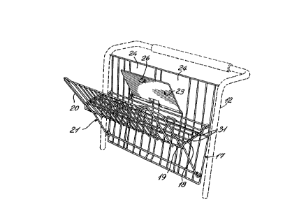
The infant seat plate 23 is also hinged adjacent
the rear wall 17 for blocking leg holes 24 formed in
the rear wall and for positioning the seat plate 23
over the wire seat frame 18. As shown in Figure 4,
biasing means in the form of a spirally wound spring 25
is secured to the seat plate 23 to bias the plate
against the rear wall 17 to obstruct the leg holes 24
formed therein. A releasable retention means in the
form of a hook member 26 is secured to the rear face
23' of the seat plate 23 and protrudes therefrom for
retention engagement of the seat plate with the wire
seat frame 18 when positioned thereover in a position
of use to arrest the seat plate 23 over the seat frame
18, as will be described in detail hereinbelow.
Having established the relationship of the
infant seat plate 23 of the present invention with
respect to the baby seat compartment formed in the rear
section of a shopping cart, there will now be described
the construction and operation of the seat plate of the

2~9l9~9

present invention. Referring now to Figures 2 to 6, it
can be seen that the seat plate 23 has a hinge edge
formed by integrally formed tubes 27 to receive a hinge
rod 28 therethrough with the rod forming part of the
rear wall 17 of the shopping cart. The biasing means,
herein a spirally wound spring 25 is secured at one end
25' in a spring attachment housing 29 and urges or
biases the seat plate 23 against the rear wall 17. The
other end 25" of the spring 25 is immovably secured to
a stationary wire rod 30. The hook member 26 is molded
integrally with the seat plate 23 which is formed of
plastic material and positioned for clipping retention
with a transverse wire rod 31 forming part of the wire
seat frame 18 when the seat plate 23 is pushed over the
seat frame 18 against the biasing force of the spring
25.
The hook member 26 has various shapes, as shown
in Figures 4 to 6, and defines a rearwardly extending
mouth opening 32 between a lip portion 33 of the flange
which extends parallel to the seat plate and which is
spaced from the rear face 23' of the seat plate 23.
The mouth opening 32 is aligned with an edge portion of
a transverse wire rod 31 of the frame 18 for receiving
at least a section of the wire rod 31 therein, as shown
in Figures 5 and 6. The hook flange, as shown in
Figures 4 and 5, is a flexible L-shape flange, whereas
the flange as shown in Figure 6 has a C-shape
configuration with the lip 33 being a small inner
extension at the end of the C-shape depending wall or
flange 34.
As shown in Figure 7, it is conceivable that the
releasing retention means be provided in the form of a
magnet 35 which is glued to the rear face 23' of the
seat plate at a position so that when the seat plate is
placed over the wire rod seat frame 18, the magnet 35
is disposed adjacent a transverse wire rod 31 and held
thereto by magnetic force. Accordingly, the magnetic

2~sl9~9
~_ - 6 -

force of the magnet 35 must exceed the spring force
acting on the seat plate to urge it towards the rear
wall. When the hinge gate 21 is displaced toward the
rear wall 17, the rod 31 will be displaced away from
the magnet and the force of the spring 25 would then
urge the seat plate against the rear wall. It is also
pointed out that although the biasing means as herein
shown is a spirally wound spring 25, it is conceivable
that other biasing elements may be provided, such as a
leaf spring, etc.
With the seat plate positioned over the seat
frame 18 and retained thereby, it is now possible for
the user of the shopping cart to use both hands for
placing a child on the seat plate 23 with the child's
legs extending through the leg holes 24 in the rear
wall.
The retention means, that is to say, the hook
member 26 may be manually released from the seat frame
by simply pulling up on the free edge 36 or side edges
of the seat plate to disengage the hook member from the
transverse wire rod 31. The spring 25 will then
automatically raise the seat panel against the rear
wall. Alternatively, by pulling the hinge gate 21
slightly rearwardly in the direction of arrow 37
towards the rear wall 17, the seat panel will
automatically disengage. Because the seat frame 18 is
slidingly attached at its opposed ends 19 to an upper
section 20 of the hinge gate 21, the opposed ends 19 of
the seat frame will rise up on the upper section 20 of
the hinge gate 21, causing the transverse wire rod 31
to move out of engagement with the mouth opening 32, in
the direction of arrow 38, releasing the seat plate and
causing the spring to urge it against the rear wall 17.
It is pointed out that the operation of the seat frame
with respect to the hinge gate is well known in the art
and described in my above-mentioned patent which is
incorporated herein by reference. The position of the

~09196g

- -

hinge gate as shown in phantom lines at 21' and the
phantom position of one of the transverse rods 31'
shows the direction of displacement of the seat frame
with respect to the rear gate and the stationary rear
wall 17 with the seat frame moving upwardly in the
direction of arrow 39.
As clearly shown in Figure 4, the hook member 26
has an aperture 40 formed adjacent thereto, and this
aperture also shows the transverse wire rod received by
the hook member.
It is within the ambit of the present invention
to cover any obvious modifications of the preferred
embodiment described herein, provided such
modifications fall within the scope of the appended
claims.

Representative Drawing
A single figure which represents the drawing illustrating the invention.
Administrative Status

For a clearer understanding of the status of the application/patent presented on this page, the site Disclaimer , as well as the definitions for Patent , Administrative Status , Maintenance Fee  and Payment History  should be consulted.

Administrative Status

Title Date
Forecasted Issue Date 1999-07-20
(22) Filed 1993-03-18
(41) Open to Public Inspection 1994-09-19
Examination Requested 1995-10-23
(45) Issued 1999-07-20
Expired 2013-03-18

Abandonment History

There is no abandonment history.

Payment History

Fee Type Anniversary Year Due Date Amount Paid Paid Date
Application Fee $0.00 1993-03-18
Registration of a document - section 124 $0.00 1993-11-02
Maintenance Fee - Application - New Act 2 1995-03-20 $100.00 1995-03-15
Maintenance Fee - Application - New Act 3 1996-03-18 $100.00 1996-03-05
Maintenance Fee - Application - New Act 4 1997-03-18 $100.00 1997-03-07
Maintenance Fee - Application - New Act 5 1998-03-18 $150.00 1998-03-18
Maintenance Fee - Application - New Act 6 1999-03-18 $150.00 1999-03-16
Final Fee $150.00 1999-04-06
Maintenance Fee - Patent - New Act 7 2000-03-20 $150.00 2000-02-17
Maintenance Fee - Patent - New Act 8 2001-03-19 $150.00 2001-01-30
Maintenance Fee - Patent - New Act 9 2002-03-18 $150.00 2002-01-25
Maintenance Fee - Patent - New Act 10 2003-03-18 $200.00 2003-01-28
Maintenance Fee - Patent - New Act 11 2004-03-18 $250.00 2004-01-26
Maintenance Fee - Patent - New Act 12 2005-03-18 $250.00 2005-01-05
Maintenance Fee - Patent - New Act 13 2006-03-20 $250.00 2006-01-05
Expired 2019 - Corrective payment/Section 78.6 $150.00 2006-10-12
Maintenance Fee - Patent - New Act 14 2007-03-19 $250.00 2007-01-15
Maintenance Fee - Patent - New Act 15 2008-03-18 $450.00 2008-02-28
Maintenance Fee - Patent - New Act 16 2009-03-18 $450.00 2009-01-29
Maintenance Fee - Patent - New Act 17 2010-03-18 $450.00 2010-01-08
Maintenance Fee - Patent - New Act 18 2011-03-18 $450.00 2010-12-21
Registration of a document - section 124 $100.00 2011-10-20
Registration of a document - section 124 $100.00 2012-02-01
Maintenance Fee - Patent - New Act 19 2012-03-19 $450.00 2012-02-24
Registration of a document - section 124 $100.00 2013-07-31
Owners on Record

Note: Records showing the ownership history in alphabetical order.

Current Owners on Record
CARI-ALL PRODUCTS INC.
Past Owners on Record
CARI-ALL INC.
CARI-ALL PRODUCTS INC.
TRUBIANO, ANTOINE
Past Owners that do not appear in the "Owners on Record" listing will appear in other documentation within the application.
Documents

To view selected files, please enter reCAPTCHA code :


To view images, click a link in the Document Description column. To download the documents, select one or more checkboxes in the first column and then click the "Download Selected in PDF format (Zip Archive)" or the "Download Selected as Single PDF" button.

List of published and non-published patent-specific documents on the CPD .

If you have any difficulty accessing content, you can call the Client Service Centre at 1-866-997-1936 or send them an e-mail at CIPO Client Service Centre.


Document
Description 
Date
(yyyy-mm-dd) 
Number of pages   Size of Image (KB) 
Cover Page 1995-06-10 1 20
Abstract 1995-06-10 1 32
Claims 1995-06-10 4 164
Drawings 1995-06-10 3 127
Description 1995-06-10 7 342
Description 1998-08-19 8 300
Claims 1998-08-19 4 144
Cover Page 1999-07-12 1 47
Representative Drawing 1999-07-12 1 19
Representative Drawing 1998-08-21 1 30
Correspondence 1999-04-06 1 46
Prosecution Correspondence 1995-10-23 1 41
Prosecution Correspondence 1995-10-23 3 116
Office Letter 1993-09-16 1 53
Office Letter 1995-11-09 1 48
Prosecution-Amendment 2006-10-12 1 45
Correspondence 2006-11-06 1 13
Assignment 2011-10-20 5 231
Assignment 2012-02-01 57 2,287
Assignment 2013-07-31 7 176
Fees 1997-03-07 1 55
Fees 1996-03-05 1 54
Fees 1995-03-15 1 59