Note: Descriptions are shown in the official language in which they were submitted.
2~~~~~'~
. 1 .
T 6586
DEVICE FOR COUNTER-CURRENTLY CONTACTING GAS AND LIQUID
The present invention relates to a device for counter-currently
contacting gas and liquid comprising a normally vertical column
having a gas inlet and a liquid outlet at its Iower end and a gas
outlet and a liquid inlet at its upper end, which column is pro-
vided with gas/liquid contacting means arranged in the column
between the gas inlet and the lfquid inlet.
Such a device is disclosed in European patent specification
No. 169 611.
In the known device a liquid distributor is arranged above the
gas/liquid contacting means. The liquid distributor comprises a
horizontal tray which is provided with distribution tubes through
which liquid can pass to below the tray and gas risers which
communicate with the gas outlet of the column. The liquid inlet of
the device debouches onto the horizontal tray.
It was found that during normal operation a large amount of
liquid is entrained with gas rising thraugh the gas risers.
It is an object of the present invention to provide a device
for counter-currently contacting gas and liquid provided with means
to reduce entrainment with at least a factor of 100 to an amount
which is about 1(i litres of liquid par 1 000 000 Nrn3 of gas.
To this end the doviae for counter-currently contacting gas and
liquid according to the present invention comprises a normally
vertical column having a gas inlet and a liquid outlet at its lower
end and a gas outlet and a liquid inlet at its upper end, which
column is provided with gas/liquid contacting means arranged In the
column between the gas inlet and the liquid inlet, and with a
gas/liquid separator arranged above the gas/liquid contacting
means, which separator comprises a horizontal collection tray
provided with passages communicating with a separation device and
with one or more vertical distribution tubes) extending through
the horizontal collection tray to the gas/liquid contacting means,
wherein the separation device has a gas outlet communicating with
the gas outlet of the column and a liquid outlet debouching onto
the collection tray, and wherein the liquid inlet debauches onto
the horizontal collection tray.
Reference is made to European patent application publication
No. 48 508 disclosing a device for counter-currently contacting gas
and liquid, wherein the gas/liquid contacting means arranged
between the gas inlet and the liquid inlet consists of a plurality
of horizontal trays provided with contact swirl tubes arranged in
openings in the tray, the contact swirl tubes have side entrances
to allow liquid collected on the tray to enter into the contact
swirl tubes for contacting gas flowing upwardly through the contact
swirl tubes. Ttte contact swirl tubes have liquid outlets which
communicate with a downcomer that debauches onto the underlying
tray. In this known device the liquid inlet debauches onto the
uppermost contacting tray and communicates with the side entrances
of the contact swirl tubes of this tray. During normal operation
liquid which is supplied into the column through the liquid inlet
is contacted with the gas flowing through the contact swirl tubes
of the uppermost tray, then it is separated from the gas stream and
passed to the underlying tray.
In the device according to the present invention the gas/liquid
separator is the uppermost tray of the column, which tray is not
used for contacting but for separation only and in this way the
very low amount of entrainment can bo obtained. Moreover th:Ls tray
is used for distributing liquid supplied through the liquid inlet
and for returning liquid that is separated in the swirl tubas.
European patant applications publication No. 83 811 and publl-
catl.on No. 124 920 disclose gas/liquid separators comprising a tray
provided with separation swirl tubes. In these publications it is
observed that these trays can be used to replace the trays in the
column as described in European patent application publication No.
48 508, however, the separation swirl tubes should then become
contact swirl tubes which are provided with a mixing chamber and
with separate inlets for gas and liquid.
s u~u~s~r
~~~tr~,~~t
- 3
Thus these publications thus disclose combining tire functions
of separation and contacting in the contact swirl tubes on one
tray. A drawback of such a combination is that good contacting will
adversely affect separating and Che reverse. Moreover, efficient
separation for each tray will require stringent measures which will
cause an increased restriction to gas flow through the tray.
The invention will now he described by way of example in more
detail with reference to the accompanying Figure showing an upper
section of the device for counter-currently contacting gas and
liquid according to the present invention.
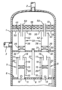
The device comprising a normally vertical column 1 having a gas
inlet (not shown) and a liquid outlet (not shown) at its lower end
and a gas outlet 2 and a liquid inlet 3 at its upper end.
The column l is provided with gas/liquid contacting means
arranged in the column 1 between the gas inlet in the lower end of
the column l (not shown) and the liquid inlet 3. The gas/liquid
contacting means comprises several contacting devices which are
axially spaced apart in the column 1. In the Figure only the
uppermost contacting device, designated with reference numeral 6,
is shown.
The contacting device 6 comprises a horizontal tray 8 provided
with two contact swirl tubes designated with reference numeral 9.
Each contact swirl tube comprises an open-ended vertical tube 10
arranged in opening 11 in the horizontal tray 8. A :Lts lower end
the vertical tube 10 is provided with side entrances :L3 (only one
is shown) communicat:Lng with the space above the horizontal tray 8,
and in the vertical tube 10 is arranged a swirl irnparting means 15
in the form o~ a plurality of vanes which irnpart rotation to a
fluid flowing upwards through the vertical tube 10. The contact
swirl tubes 9 further comprises a gas outlet 16 and a liquid outlet
17 communicating with the upper end of the vertical tube 10. The
liquid outlet 17 communicates with a annular channel 19 between the
vertical tube 10 and an outer tube 20; the annular channel 19
debouches onto the horizontal tray 8. The contacting device 6
. 4 .
furthermore includes a downcomer 21 for conveying liquid collected
on the tray 8 to the underlying contacting device (not shown),
The column 1 is further provided with a gas/li,quid separator 30
arranged above the gas/liquid contacting means 6, which separator
30 comprises a horizontal collection tray 31 provided with passages
32 communicating with a separation device in the form of separation
swirl tubes 33 and with a vertical distribution tube 37 extending
through the horizontal collection tray 31 to the gas/liquid con-
tacting means 6. Each separation swirl tube 33 consists of a verti-
cal tube 38 communicating with the passage 32 provided with a swirl
imparting means 39 in the form of a plurality of vanes arranged at
its lower end. The separation device in the form of the separation
swirl tubes 33 has a gas outlet in the form of gas outlets 42
communicating with the gas outlet 2 of the column l and a liquid
outlet in the form of liquid outlets 43 debouching onto the collec-
tion tray 31. The liquid inlet 3 debouches onto the horizontal
collection tray 31.
During normal operatiorE, gas is supplied to the column 1
through the gas inlet (not shown) which is arranged below the
gas/liquid contacting means 6. The gas is allowed to pass upwards
through the column 1.
Liquid is supplied to the column 1 through the liquid inlet 3
and flows over the collection tray 31 until the liquid level on the
collection tray 31 is such that liquid flows downwards through the
distribution tube 37 onto the uppermost horizontal tray 8 of the ,
gas/liquid contacting means, At the tray 8 ascending gag and
descending liquid ara braught in contact which each other in the
contact swirl, tubes 9. Liquid collected on the horizontal tray 8
enters into the contact swirl tubes 9 through sida entrances 13 and
gas enters the contact swirl tubes 9 from under horizontal tray 8.
Liquid and gas are contacted in the mixing chamber of the vertical
tubes 10 upstream of the swirl imparting means 15 which cause
liquid and gas to separate. Gas flows through gas outlet 16 and
liquid through liquid outlet 17 via annular channel 19 onto the
vertical tray 8.
CA 02092237 2002-06-17
63293-3566
- 5 -
The ascending gas flows through passages 32 to the separation
swirl tubes 33 of the gas/liquid separator 30 to remove from the
gas entrained liquid. Gas free of entrained liquid leaves the gas
outlet 2 of the column 1 and liquid flows through the liquid
outlets 43 on the collecting tray 31. This liquid together with the
liquid supplied through liquid inlet 3 flows through distribution
tube 37 to the uppermost contacting device 6 of the contacting
means.
Liquid flows downwardly through downcomer 21 to the contacting
device underlying contacting device 6. Liquid. from the lowermost
contacting device (not shown) through the downcomer of that device
leaves the column 1 through the liquid outlet (not shown).
An advantage of the device for counter-currently contacting gas
and liquid according to the present invention is that on the
uppermost tray, the gas/liquid separator, the separation function
is separated from the contacting function. Only in this way the
very small amount of liquid entrainment in treated gas can be
obtained. A further advantage is that the collection tray pertain-
ing to the gas/liquid separator is used as distribution tray for
the incoming liquid.
The gas/liquid separator 30 can furthermore be provided with
extended gas outlets 50 extending through a demistor mat, and with
secondary gas o~.~tler_s 55 in a tray 56 which is arranged under the
demistor mat 51.
The contacting device 6 may comprise more than two contact
swirl tubes 9, and the gas/liquid separator 30 can be provided with
more than two separation swirl tubes 33 and with more than one
vertical distribution tube 37. In addition to the liquid outlets 17
of the contact swirl tubes 9 and the liquid outlet 43 of the
separation swirl tubes 33, the upper part of the wall of the
vertical tubes 10 and 38 can be provided with axial slits.
The gas/liquid contacting means can consis t of trays provided
with contact swirl tubes as shown in the Figure, however, the
gas/liquid contacting means may also consist of conventional
contact trays, structured packing or random packing.
The device for Gaunter-currently cantaating gas and liquid
according to the present invention is particularly suitable for
drying natural gas by contacting the natural gas with glycol.