Note: Descriptions are shown in the official language in which they were submitted.
ANTIFOULING STRUCTURES
BACKGROUND OF THE INVENTION
The present invention relates to an antifouling structure
and method effective to inhibit deposition of marine organisms
such as barnacles, blue mussel and seaweed.
Offshore structures in contact with seawater are always
exposed to contamination by marine organisms, resulting in
appearance damage or malfunction. For instance, ships suffer
a driving force drop when many forms of oceanic organisms are
deposited onto their bottoms, etc., and thermoelectric power
plants are forced to stop operation when various forms of
oceanic organisms are built up on their seawater intake pits,
because a serious problem arises in connection with the
circulation of a seawater serving as a cooling medium.
Among scores of techniques for inhibiting marine deposits
studied so far in the art, there is typically now available a
method for protecting an offshore structure against
contamination, in which the surface of that structure in
contact with seawater is coated with a coating material
containing cuprous oxide or organotin.
A grave problem with this conventional method, however, is
that the coating material has a service life as short as one
year, since even when applied in a thick layer, it is likely
to peel away; there is needed troublesome maintenance work in
which the coating material must be renewed per year.
Another method is disclosed in JP-A-60-209505 that is
directed to a member for inhibiting marine deposits, which
comprises copper or a copper (e.g., Cu-Ni) alloy. However,
.
~ 9w~
this method is found to be less than satisfactory in terms of
corrosion resistance and antifouling effect.
Our years of study have now revealed that the application
of a beryllium-copper alloy to an offshore structure achieves
a much-more excellent antifouling effect. The reason would be
that beryllium and copper ions interact synergistically,
producing a great effect on inhibiting oceanic organisms from
having access to the offshore structure and preventing their
propagation. In other words, we have now found that the
beryllium-copper alloy has a combined effect both on
inhibiting marine deposits and on the continued liberation of
copper ions.
A main object of the invention is to provide an
antifouling structure that excels in antifouling properties
and durability, dispenses with maintenance work, offers no
toxicity problem, and is easy to handle.
Another object of the invention is to provide a method for
fixing an antifouling structure to an application member,
which enables the antifouling structure to be well fixed to
the application member, excel in antifouling properties and
durability, dispense with maintenance work, and present no
toxicity problem.
A further object of the invention is to provide a
structure for preventing deposition of organisms, which is
well fixed to an application (or associated )member, excels in
antifouling properties and durability, dispenses with
maintenance work, and offers no toxicity problem.
2~22~
SUMMARY OF THE INVENTION
According to one aspect of the invention, there is
provicled an antifouling structure characterized by being a
flexible thin sheet made up of a copper alloy and an
insulating material layer. Preferably, this antifouling
structure comprises a copper alloy layer, an insulating
material layer provided on the surface of the copper alloy
layer, and an adhesive material layer provided on the
insulating material layer. More preferably, the insulating
material layer is bonded or otherwise fixed to a metal
member.
According to another aspect of the invention, there is
provided an antifouling structure characterized by being an
inflexible sheet member made up of a thin sheet made of a
copper alloy and an insulator layer. Preferably, an
additional adhesive layer is provided on the surface of the
insulator layer. More preferably, the member to which the
adhesive layer is bonded is a metal. By way of example but
not by way of limitation, the insulator layer may be formed
of synthetic resin, tile material or hard rubber.
According to a further aspect of the invention, there
is provided a method for installing an antifouling
structure, characterized in that an insulator layer is
formed on the surface of a metal member, and a thin sheet
made up of a copper alloy is bonded to the surface of the
insulator layer.
According to a still further aspect of the invention,
there is provided a structure for inhibiting deposition of
organisms, characterized by comprising a metal member, an
insulator layer formed on the surface of the metal member,
and a metal gauze made up of a copper alloy is bonded to
the surface of the insulator layer.
BRIEF DESCRIPTION OF THE D~AWINGS
The invention will now be explained, more specifically
but not exclusively, with reference to the accompanying
drawings, in which:
Figure 1 is a schematic, perspective view of the first
embodiment of the antifouling structure according to the
first aspect of the invention,
Figure 2 is a schematic, sectional view showing -the
first embodiment of the antifouling structure that is
bonded to the inner wall of a water intake pipe,
Figure 3 is a schematic, sectional view of the second
embodiment of the antifouling structure according to the
first aspect of the invention,
Figure 4 is a schematic representation of what state an
oxide film of the beryllium-copper alloy according to the
invention is in,
Figure 5 is a schematic representation of what state an
oxide film of a cupronickel, provided for comparative
purposes, is in,
Figure 6 is a schematic illustration wherein beryllium
copper is compared with cupronickel in terms of changes-
with-time in the amount of copper ions liberated and the
thickness of corrosion product,
Figure 7 is a partly cut-away, perspective view showing
the first embodiment of the second aspect of the invention,
:
,
~22~
Figure 8 is a perspective view showing an iron pipe
used in the first embodiment of the second aspect of the
invention,
F'igure 9 is a representation of the shape of panels
used in the second embodi.ment according to the second
aspect of the invention,
Figure 10 is a partial perspective view showing an iron
pipe used in the second embodiment according the second
aspect of the invention,
Figure 11 is a perspective view showing panels used in
the third embodiment according to the second aspect of the
invention,
Figure 12 is a sectional view showing an iron pipe used
in the third embodiment according to the second aspect of
the invention,
Figure 13 is a plan view showing tiles used in the
fourth embodiment according to the second aspect of the
invention,
Figure 14 is a sectional view showing an iron pipe used
in the fourth embodiment according to the second aspect of
the invention,
Figure 15 is an illustration of how the antifouling
structure is installed in the first embodiment according to
the third aspect of the invention,
Figure 16 is an illustration of how the antifouling
structure is installed in the second embodiment according
to the third aspect of the invention,
Figure 17 is a perspective view showing a metal gauze
of the first embodiment of the organism deposition-
22~
inhib:iting structure according to the fourth aspect of theinvention,
F:igure 18 is a schematic, sectional view showing the
organ:ism deposition-inhibiting structure to which the metal
gauze shown in FIGURE 17 is bonded,
Figure 19 is a perspective view showing a punching
metal of the organism deposition-inhibiting structure
according to the second embodiment according to the fourth
aspect of the invention,
Figure 20(A) is a perspective view showing a foil
member of the organism deposition-inhibiting structure
according to the third aspect of the invention, and Figure
20(B) is a perspective view showing the foil member to
which tension is being applied, and
Figure 21 is a perspective view showing a metal wire
member of the organism deposition-inhibiting structure
according to the fourth embodiment according to the fourth
aspect of the invention.
DESCRIPTION OF THE PREFERRED EMBODIMENTS
It is preferable to use a beryllium-copper alloy for the
copper alloy in the invention. This beryllium-copper alloy
has a beryllium content ranging from 0.2% by weight to 2.8% by
weight, and may be selected from the group consisting of Be-
Cu, Be-Co-Cu, Be-Co-Si-Cu and Be-Ni-Cu alloys.
Typical compositions of the copper alloy used in the
invention are:
(1) 0.2 to 1.0% by weight of beryllium, 2.4 to 2.7% by weight
of cobalt and the balance being copper and inevitable
:.
7 ~226~
impurities,
(2) 0.2 to 1.0% by weight of beryllium, 1.4 to 2.2% by weight
of nickel and the balance being copper and inevitable
i.mpurities,
(3) 1.0 to 2.0% by weight of beryllium, 0.2 to 0.6% by weight
of cobalt and the balance being copper and inevitable
impurities, and
(4) 1.6 to 2.8% by weight of beryllium, 0.4 to 1.0~ by weight
of cobalt, 0.2 to 0.35% by weight of silicon and the
balance being copper and inevitable impurities.
Preferably, the contents of beryllium (Be), cobalt (Co~,
nickel ~Ni) and silicon (Si) selectively incorporated in the
copper alloy lie in the respective ranges:
Beryllium - 0.2 to 2.8 % by weight
Cobalt - 0.2 to 2.7% by weight
Nickel - 1.4 to 2.2% by weight
Silicon - 0.2 to 0.35% by weight
Set out below are what purpose the above elements are
added for and why the upper and lower limits thereof are set
at the above values.
Bervllium: 0.2-2.8% by weiaht
Beryllium is used to (1) protect the structure, when
immersed in seawater, against contamination by liberating
beryllium ions, (2) improve the strength and properties, e.g.,
corrosion resistance, of the copper alloy, (3) enhance the
productivity of the copper alloy as by heat treatment and
grain size regulation, and (4) improve the processabllity and
castability of the copper alloy. At below 0.2% by weight the
above-described effects (1)-(4) are unachievable. At higher
8 ;~926g
than 2.8% by weight, not only is there some metalleability
drop but a cost effective problem arises as well.
Cobalt: 0.2 to 2.7% bv weiaht
Cobalt is used to form a fine CoBe compound and disperse
it throughout the alloy matrix, thereby improving the
mechanical properties and productivity of the copper alloy.
At less than 0.2% by weight this effect is not well
achievable. At higher than 2.7% by weight, not only is there
some material flowability drop but there is little or no
improvement in the above-described effect as well. In
addition, a cost-effective problem arises.
Nickel: 1.4-2.2% bv weiaht
Nickel is used to form a fine NiBe compound and disperse
it throughout the alloy matrix, thereby improving the
mechanical properties and productivity of the copper alloy.
At less than 1.4% by weight this effect is not well
achievable. At higher than 2.2% by weight, not only is there
some material flowability drop but there is little or no
improvement in the above-described effect as well. In
addition, a cost-effective problem arises.
Silicon: 0.2-0.35% bv weiaht
Silicon is used to improve the material flowability of the
copper alloy. At less than 0.2% by weight this effect is not
well achievable. At higher than 0.35% by weight the resulting
alloy becomes brittle with a toughness drop.
As a result of our years of experimentation and research,
it has turned out that the beryllium-copper alloy has a
combined effect both on preventing contamination and on the
continued liberation of copper ions. Detailed explanation
~$~2~
will now be made to the antifouling effect and the continued
action on liberating copper ions.
(1) Antifouling Effect
As well known from literature, the order of ionization
tendency among beryllium, copper and nickel is expressed by
Be>Ni>Cu
In other words, beryllium ions are more likely to be liberated
than copper ions, and copper ions are more likely to be
liberated than nickel ions. In the case of a beryllium-copper
combination, beryllium is first ionized to form a local cell,
which has an effect on preventing deposition of oceanic life
contaminants due to its current effect, while beryllium ions
take on the form of internal oxidation. By this internal
oxidation, a BeO film is first formed, as typically shown in
FIGURE 4. This BeO film, because of being porous, allows
copper ions to be liberated, forming Cu20+BeO on the surface.
This liberation of copper ions into seawater produces an
antifouling effect.
(2) Continued Action on Liberating Copper Ions
The above-mentioned effect (1) on preventing conta~ination
makes another contribution to providing a continued liberation
of copper ions; that is, the beryllium-copper combination
enables the antifouling function to be maintained ceaselessly.
While in contact with seawater, the beryllium-copper
combination forms on its surface an intimate surface oxide
(Cu20), just below which a porous oxide film of BeO is formed,
as can be seen from FIGURE 4. Thus, the liberation of copper
ions into seawater is maintained, while this film increases in
volume by the oxidation. When the volume increase reaches a
lo 2~22~ -
certain level, the surface oxide film peels away from the
porous oxide or BeO layer. This would enable electrochemical
action and the liberation of copper ions to be maintained over
an ext;ended period of time.
The continued action of the beryllium copper on the
liberation of copper ions will now be explained with reference
to FIGURE 6 that is a graphic representation showing the
results of comparison of beryllium copper with cupronickel.
When the corrosion (oxidation) product reaches a certain
thickness, it peels away from the beryllium copper (seCu), as
can be best seen from FIGURE 6. Then, the beryllium-copper
alloy is again exposed on the surface to seawater, and
corroded or oxidized for oxide film growth. When this film
grows to a certain thickness level, it peels away from the
beryllium copper. This process is repeated over and over.
The liberation of copper ions, on the other hand, is likely to
be reduced with an increase in the thickness of the oxidation
product. As the oxidation product peels away, however, the
beryllium-copper alloy is again exposed on the surface to
seawater, so that there can be an increase in the amount of
the copper ions liberated. Thus, the increase and decrease in
the amount of the copper ions liberated occur alternately.
The beryllium-copper alloy used in the invention enables
copper ions to be continuously liberated by the peeling-off of
the oxide film. As a result, the amount of contaminants
deposited onto the surface of the beryllium copper is little,
if any.
This is in contrast to the comparative cupronickel (CuNi),
as can be seen from FIGURE 5. With the passing of some years,
~ . ~
.
2 ~ ~
an intimate nickel oxide (Nio2) or copper oxide (Cu20) layer
is formed on the surface of the cupronickel, reducing the
liberation of copper ions, as can be seen from FIGURE 6.
According to the order of ionization tendency (Be>Ni>Cu), this
woùld be due to the fact the nickel (Ni) is preferentially
ionized to form a local cell and so an intimate oxide is
formed on the surface of the cupronickel, as can be seen from
FIGURE 5. As can be seen from FIGURE 6, the thickness of the
corrosion product on the cupronickel increases with time in an
early stage, but its growth rate decreases as time goes by.
With this, there is a decrease in the amount of the copper
ions liberated. In addition, the corrosion product is less
likely to peel away from the cupronickel that from the
beryllium copper. Thus, the quantity of the copper ions
liberated remains low, making the antifouling effect slender.
It is to be noted that the facts that a beryllium-copper
alloy has a remarkable antifouling effect and provides a
continued liberation of copper ions have been discovered by us
for the first time. Insofar as we are concerned, never until
now have such facts been referred to or indicated in
literature.
It has also been confirmed that not only does a beryllium
alloy pose no toxicity problem at all, but its service life in
seawater is as long as that of aluminum pitch copper or white
brass.
For practical beryllium alloys, various alloys inclusive
of JIS 11 ALLOY having a beryllium content of 0.2 to 0.6% by
weight and JIS 25 ALLOY having a beryllium content of 1.8 to
2.0% by weight are now available in the art. In view of the
:
12 ~ .32~
antifouling effect, however a beryllium content of at least
1.60% by weight is preferable. At a beryllium content higher
than 2.8% by weight, beryllium does no longer form any further
solid solution with copper. In other words, the resulting
alloy excels in the antifouling effect but undergoes a gradual
decrease in metalleability.
EMBODIMENTS OF THE FIRST ASPECT OF THE INVENTION
Referring now to FIGURE l! there is shown the first
embodiment of the first aspect of the invention.
In the first embodiment, an insulating material layer 2 is
formed on the surface of a thin sheet form of copper alloy
layer 1 made up of, for instance, beryllium-copper alloy.
This sheet form of antifouling structure 3 is in a thin sheet
form, and is of flexibility as well. Preferably, the
beryllium-copper alloy layer 1, for instance, may be formed of
Be-Co, Be-Ni and ~e-Co-Si base copper alloys.
For the insulating material layer 2, for instance, methyl
methacrylate-modified natural rubber, nitrile rubber and
chlorinated rubber may be used alone or in combination of two
or more. The rubber is dissolved in a suitable solvent for
priming or other treatments, coated on the required surface
area of the beryllium alloy layer 1, and dried to obtain an
insulating material layer having a given thickness. For
instance, the insulating material layer 2 may have a thickness
of about 5 to 20 mm, typically about 10 mm.
Practically, this antifouling structure 3 may be bonded to
the inner face of a water intake pipe (water-circulation
pipe), for instance. A typical example of the structure of
.. ~ ..
the antifouling structure 3 is shown in FIGURE 2. The water
intake pipe 5 is formed of iron, and provided on the surface
with the insulating material layer 2, which is then provided
on the surface with the beryllium-copper alloy layer 1. It is
this beryllium-copper alloy layer 1 that is exposed to
seawater or water. It is here noted that the insulating
material layer 2 is inhibited from corrosion due to a cell
action, because the beryllium-copper alloy layer 1 is in no
contact with the iron 5.
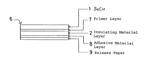
The second embodiment of the first aspect of the invention
is illustrated in FIGURE 3.
This embodies an antifouling structure 6 that can be
bonded to a metal member in contact with seawater, for
instance, a water intake pipe.
The antifouling structure 6 comprises, in order from the
surface, a beryllium-copper alloy layer 1, a primer layer 7,
an insulating material layer 2, an adhesive material layer 8
and a release paper 9.
The primer layer 7 is interposed between the beryllium-
copper alloy layer 1 and the insulating material layer 2, and
is made of material that is well compatible with them for
their bonding.
The adhesive material 8 is provided in the form of a layer
of 0.05 to 2 mm in thickness.
The release paper 9 applied on the surface of the adhesive
layer 8, is removed when the antifouling structure 6 is bonded
to an application member. This release paper 9 is used to
prevent one antifouling structure from sticking to another or
something during storage or handling.
.
,
.. . ..
'
- ,,
14 ~22~
EMsoDIMENTs OE THE SECOND ASPECT OE THE INVENTION
The first embodiment of the second aspect of the invention
will now be explained with reference to Figs. 7 and 8.
This embodies the application of the invention to an iron
pipe through which seawater flows.
An adhesive agent layer 22 is applied on the inner
peripheral wall of a cylindrical iron pipe 21. A panel 23
formed as of hard resin is fixed to the iron pipe 21 as by
bolts, screws, etc., through the adhesive layer 22. An array
of panels 23 are fixed in place by connecting the adjacent
panels by male ~23a)-and-female (23b) fitting. The adhesive
agent layer 24 is coated on the surface of each panel 23, and
a thin sheet form of beryllium-copper alloy 25 is applied to
the adhesive agent layer 24.
This beryllium-copper alloy has a combined effect both on
the exertion of the antifouling function and on the continued
liberation of copper ions, as already mentioned.
The second embodiment of the second aspect of the
invention will now be explained with reference to Figs. 9 and
10 .
This embodies the application (or lining) of a beryllium-
copper alloy thin sheet to a part of the inner peripheral wall
of the iron pipe 21 according to the first embodiment of the
second aspect of the invention. An adhesive agent layer 22 is
applied on the surface of the iron pipe 21, and an array of
panels 26, each made of hard resin, are fixed on the adhesive
layer 22 as by bolts, although not shown. These panels 26,
each extending in the axial direction of the iron pipe 21, are
juxtaposed with each other in the peripheral direction of the
~22~
iron pipe 21. The beryllium-copper alloy thin sheet 28 is
bonded by an adhesive agent 29 into recesses 26a and 26b
formed in both edges of each panel 26.
The third embodiment of the second aspect of the invention
will now be explained with reference to Figs. 11 and 12.
In this embodiment, a rectangular panel 30 is used instead
of the panel 23 of continuous length according to the first
embodiment. This rectangular panel 30, again formed of hard
resin, may be applied to local areas of an iron pipe 21, for
instance, its bends, corners, ends, and so on. This panel 30,
because of being of small size, is favorably used to enhance
the effect on the partial or local prevention of deposition of
life contaminants. One rectangular panel 30 can be closely
juxtaposed to the adjacent panels by male (30a)-and-female
(30b) fitting. These panels are all of electrical insulating
properties. As shown in FIGURE 12, an adhesive agent layer 24
is applied on the surface of each panel 30, and a beryllium-
copper alloy thin sheet is applied on the layer 24.
The fourth embodiment of the second aspect of the
invention will be explained with reference to Figs. 13 and 14.
In this embodiment, a beryllium-copper alloy is adhesively
fixed onto a lattice array of rectangular, electrically
insulating, ceramic tiles 32. Each tile 32 is provided with
recesses 32a in and along its four sides. As illustrated,
four tiles 32 are bolted at 34 such that they are firmly fixed
to the iron pipe 21. Although not illustrated, a beryllium-
copper alloy thin sheet 25 is applied on the surfaces of the
tiles 32 through an adhesive agent layer 24.
16
2 ~
EMBODIMENTS OF THE THIRD ASPECT OF THE INVENTION
Illustrated in FIGURE 15 is the first embodiment of the
third aspect of the invention.
This embodies the application of the invention to a pipe
for seawater circulation that is used in a power plant cooling
system.
A tile 42 made of electrical insulating material is bolted
at 43 on the inner peripheral wall of a cylindrical iron pipe
41. The tile 42 is in a polygonal sheet form. The head of
the bolt 43 is located in a recess 42a formed in the tile 42.
It is here noted that the depth of the recess 42a is larger
than the height of the head of the bolt 43. One tile is
closely juxtaposed to the adjacent tiles 42 on the iron pipe
41.
Then, a thin sheet 45 of beryllium copper 45 is applied
onto the surface of each tile 42. This thin sheet 45 is
provided in a rolled form, and is previously coated thereon
with an adhesive agent.
Our years of experimentation and research teach us that a
beryllium-copper alloy has a combined effect both on the
exertion of the antifouling function and on the continued
liberation of copper ions, as already mentioned.
Illustrated in FIGURE 16 is the second embodiment of the
third aspect of the invention.
In this embodiment, an insulating material layer 46 is
used in place of the tile 42 that is employed as the
insulating material in the first embodiment.
The insulating material layer 46 is applied on the inner
wall 41a of a pipe 41, and then dried, after which a thin
17
~9~6~
sheet 45 made of a beryllium-copper alloy is applied on the
layer ~6. It is preferable to this end to use an adhesive
agent or a beryllium-copper alloy thin sheet that has an
adhes:ive agent applied on its surface.
The second embodiment is well resistant to a seawater
attack, as in the case of the first embodiment, and so has a
good-enough antifouling effect.
EMBODIMENTS OF THE ~Ou~l~ ASPECT OF THE INVENTION
The first embodiment of the fourth aspect of the invention
will now be explained with reference to Figs. 17 and 1~.
This embodies the application of the invention to a pipe
for seawater circulation that is used in a power plant cooling
system.
As shown in FIGURE 18, an electrical insulating glass,
concrete or, preferably, resinous material 62 is bonded to the
inner peripheral wall of a cylindrical iron pipe 61. Then, a
metal gauze 65 made of beryllium copper is applied onto the
surface of the resin 62. As shown in FIGURE 17, the beryllium
copper gauze 65 is provided in a rolled form, and the resin 62
has an adhesive layer on its surface.
Illustrated in FIGURE 19 is the second embodiment of the
fourth aspect of the invention.
In this embodiment, a punching metal 66 is used for the
metal gauze 65 in the first embodiment. The punching metal 66
is made of a beryllium-copper alloy, and comprises a foil
member 66b having a number small holes 66c.
According to this embodiment, an insulating material layer
66 is coated on the inner peripheral wall 61a of a pipe 61,
and then dried, after which the punching metal 66 is applied
,'~
18
- ' 2 ~ 9
on the insulating material layer 66. It is preferable to this
end to use an adhesive agent or a punching metal having an
adhesive agent coated on its surface.
The second embodiment is well resistant to a seawater
attack, as in the case of the first embodiment mentioned
above, and so has an excellent antifouling effect.
Illustrated in FIGURE 20 is the third embodiment of the
fourth aspect of the invention.
In this embodiment, a foil member that is holed under
tension is used in place of the punching metal 66 in the
second embodiment. As shown in FIGURE 20(A), the foil member
68 is made of a beryllium-copper alloy, and is provided with
a number of slits 68a that deform into rectangular or round
small holes 68a under tension.
Illustrated in FIGURE 21 is the fourth embodiment of the
fourth aspect of the invention.
In this embodiment, a metal wire member 70 that deforms
into a metal gauze under tension is used in place of the
punching metal 66 in the second embodiment. This metal wire
member 70 is made of a beryllium-copper alloy, and deforms
into a metal gauze upon tensioned in the direction shown by an
arrow in FIGURE 21.
With the antifouling structure constructed according to
the first aspect of the invention, which has a copper alloy
layer formed on its surface, a good-enough effect on the
prevention of deposition of life contaminants is achieved
partly because of the antifouling action of the copper alloy
and partly because of the action of the copper alloy on the
continued liberation of copper ions. In addition, this
19 ~'2~
antifouling structure can be mounted in place with a good-
enough working efficiency, because it is in a thin sheet form
and possesses flexibility. Moreover, it assures that any
corrosion due to a cell action can be avoided, because of the
provision of the insulating material layer that inhibits the
copper alloy from being in direct contact with the metal to be
bonded.
The antifouling structure constructed according to the
second aspect of the invention can be attached to iron sheets,
iron pipes, etc., in simple operation, because it is not only
of a unit type but of small size. In addition, it excels in
corrosion resistance due to the provision of the insulator
layer that inhibits electrolytic corrosion. Moreover, it can
be maintained in less troublesome operation, offers no
toxicity problem, and can effectively prevent deposition of
oceanic organisms.
With the method for attaching an antifouling structure
according to the third aspect of the invention, it is possible
to attach the antifouling structure for inhibiting deposition
of oceanic organisms in relatively simple operation. The
antifouling structure provided by this method can be
maintained in less troublesome operation, presents no toxicity
problem, and can effectively inhibit deposition of marine
organisms.
With the structure for inhibiting deposition of marine
organisms according to the fourth aspect of the invention, it
is possible to install a structure for inhibiting marine
deposits in relatively simple operation. The antifouling
structure installed by this method excels in corrosion
:
resistance, can be maintained in less troublesome operation,
presents no toxicity problem, and can effectively inhibit
marine deposits.