Note: Descriptions are shown in the official language in which they were submitted.
2092378
" A SIMULATION-PREVENTING TURNSTILE "
This invention concerns turnstiles used to detect the
entrance and/or the exit to/from controlled areas, in
particular it concerns a simulation-preventing turnstile
adapted to check that people actually walk through the
monitored passage.
Various turnstile types are already known, suitable for
monitoring access to shops, subway stations, and other
facilities of many kinds and, recently, also the access
to working areas. Said turnstiles allow people to walk
through only after the user has obtained clearance from
dedicated members, by means of a magnetically, optically
or similarly readable personal badge. Once said clear-
ance has been <liven, an electronic control unit provides
temporary unlocking of the turnstile revolving member,
which normally prevents passage in front of the turn-
stile. Very often, 'the same control unit is connected
with sensors of various types, suitable for detecting
turnstile unauthorized sidestepping or walking-through
attempts, in order to trigger suitable optical and/or
acoustical alarm signals. Furthermore, in certain cases,
the control unit= is given also the task of checking that the
user, once he has obtained clearance for walking-through,
actually gets t:o actuate the turnstile revolving member
within an adequate predetermined maximum time lag.
20923~'g
- 2 -
In fact, in some cares the turnstile monitoring functi-
ion, rather than preventing unauthorized people from
walking-through, is meant to checking and recording that
the user has a.ctuall.y walked-through. Reference is made
herein, for instance, to the automatic monitoring of
working periods, therefore of the time during which the
personnel has ,actually attended work, which is absolute-
1y necessary in the case of large plants or factories
and in any case when a large number of workers have to
access the samf~ working post.
In this type of application the known turnstiles prove
unsatisfactory in that it is very simple to simulate the
walking-through and therefore to deceive the personnel
attendance monitoring system. In fact, after having
obtained clearance for walking-through, from the reader
of personal badges o:r equivalent device, it is enough to
actuate the turnstile revolving member for instance by
hand, without actually walking through it, thereby
completing the required walking-through procedure and
obtaining a rE~cordi:ng of having reached the working
post.
Therefore, it is an object of this invention to provide
a device which, in addition to performing all the funct-
ions pertaining' to the previously known turnstiles, has
a further ability to detect and report simulated walk-
2092378
.. - 3 -
ing-through ati~empts performed by the user.
The above object is met by means of a turnstile provided
with an electronic control unit connected to a timer and
to optical ancL/or acoustical alarm means, and further
including a sensor located downstream from the turnstile
revolving member, adapted to detect if the user actually
walks through, and to send a signal thereof to the
control unit, whereby the latter, in case of negative
occurrence, triggers a special alarm signal.
The simulation-preventing turnstile according to this
invention has the advantage that, compared with the
state of the a:rt, it provides a more flexible sequence
of events required for the control unit to recognize a
walking-through procE~dure as being correct, whereby it
becomes virtually impossible to fulfill the required
procedure by simulated operations.
The above and other advantages of the simulation-
preventing turnstile according to this invention will
become more apparent from the following detailed
description of a preferred embodiment thereof, referring
to the attached drawings, wherein:
Figure 1 is a perspective view of a simulation-prevent-
ing turnstile a~~cording to this invention; and
Figure 2 is a flow diagram showing the operation of the
turnstile of Fi~~ure 1.
209 ~3 78
-
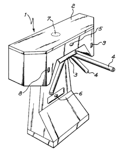
Referring now to Figure 1, as it is shown therein, the
simulation-preventing turnstile according to this invent-
ion, shown in general at 1, comprises a housing 2 from
which there projects at an angle the turnstile revolving
member, which in this case is the tripod type. Therefore
it includes three arms 4 integral with head member 3 and
diverging the rei=rom at. respective points located 120 degrees
apart just in such a way as to form the so-called tripod.
Before and after each 120 degree rotation of head member
3 caused by a user walking through, one of the three
diverging arms 4 gets to be located in a horizontal posit-
ion, wherein it blocks the passage in front of turnstile
1, while the other pair of diverging arms 4 are in a
substantially sloping position. However the turnstile may
be of the cross-shaped revolving member type wherein the
revolving member rotation axis is horizontal, rather
than substantially vertical, as in the tripod type turn-
stile. An electronic: control unit, preferably a micro-
processor, located within housing 2 and therefore not
shown, is connected with all the sensor means the turn-
stile is provided wit=h. As it will be explained in detail
in the followings, said unit continuously monitors the turnstile
condition, and the development of the sequence of events
corresponding 1.o the user walking-through, and in addit-
ion it verifies that said sequence gets completed within a
zo~z3 78
.. _
predetermined maximum time lag. Any exception to that
sequence of events will then result in an alarm signal
and possibily the user having caused it will be
identified.
When unlocked ~by the control unit, the above head member
3, may revolve, together with arms 4, in the direction
it is enabled to, amd the angular position thereof is
constantly known to the electronic control unit by means
of three sensors, peferably Hall effect type sensors,
not shown in the drawing in that they are received
within housing 2. Similarly, there is not shown the pair
of personal badge readers, or equivalent devices, which
for sake of simplicity are called readers in the follow-
ing. They are provif.ed at the turnstile ends, and they
are necessary f=or thc~ temporary unlocking of head member
3 and arms 4, thereby enabling them to revolve in one
direction. In addition, turnstile 1 includes a pair of
photoelectric cells '.p and 6 located above and below that
arm 4 which is in a horizontal position, respectively,
adapte d to detect anauthorized walking-through attempts,
above or under said arm 4, said attempts being generally
called "strid.e over attempts". The stride-over
preventing barrier i:~ in general completed by a pressure
sensor 7, shown in dashed lines in the drawing, located
within housing 2, and sensitive to a weight bearing on
209 Z3 78
-
the upper surface o_E said housing, in order to give a
signal when a person attempts to stride over turnstile 1
by walking, or in an_y case leaning on said surface.
The simulation-preventing turnstile according to this
invention includes eventually a pair of photoelectric
cells 8 and 9 located on the sides of housing 2, ahead
and after revolving head member 3. Blinding of that
photoelectric ~~ell 8 or 9 which is located downstream
from head member 3, in the passing direction of the user
is the final event of the sequence of events required by
the control unit tc> record the walking-through as a
correct one, and it certifies that the user has actually
walked through the turnstile passage after having pushed
the horizontal arm 4 and having rotated head member 3 by
120 degrees. In the following, the photoelectric cell
located downstream, in the user passing direction will
be called dowr.~.stream photoelectric cell, for sake of
simplicity.
In Figure 2 there i~~ shown the algorithm used in said
microprocessor-based electronic control unit, controll-
ing the simulation-preventing turnstile operation
according to this invention. Normally, said turnstile is
in a waiting condition, shown within dashed line box FA,
wherein the pa~;sage :is closed in that no clearance has
been given by the reader to a temporary unlocking of the
209 23 ?8
_~_
head member and the reby to the arm actually blocking
said passage. Instead, in said condition, photoelectric
cells 5 and 6 are actuated, as well as pressure sensor
7, in order to watch over possible attempts to stride
over the barrier.
When the user has made himself recognized by his
personal badge, a clearance signal provided by one of
the readers gets the turnstile out of waiting condition
FA and the monitoring over the sequence of events or
conditions corresponding to the user walking-through is
started. First of all, the preliminary step is complet-
ed, as shown by the dashed line block FP, wherein a
"timer" 11 is initialized. The timer checks that the
user causes a regular 120 degree rotation of the turn-
stile head member, within a reasonable and predetermined
time lag. In aciditio:n, preliminary step FP provides for
a binary variable, c>r "flag" VB, to be set, at 12, to
one of the two values thereof, for instance zero, for
the reasons to be Explained in the following. During
next step, or monitoring step, shown by dashed line box
FC, provision is made so that, while said head member
rotates, a reference point thereof reaches in sequence
the three Hall effect sensors mentioned above, the
latter of which. corresponds to having completed the 120
degree rotation of said head member. Boxes 21, 23 and 25
20 g 23 78
_8_
of Figure 2 show the three tests on turnstile head
member rotation, performed in sequence by the control
unit by means of said three Hall effect sensors. In case
the time lag by which said timer had been initialized in
preliminary step F'P expires, an "incorrect walking-
through" alarm signal will be issued at the first among
checks 21, 23,. 25 having produced a negative result. In
addition, in order that the user walking-through procedure
be recognized as correct, it is necessary that during
the period of time included between the moments in which
the first two head member rotation sensors are reached,
upper photoelectric cell 5 is blinded out by the user.
In fact, a positive result of check 22 on this event
results in a change 22' of the value of the binary
variable or "flag" VB mentioned above, and a subsequent
check 24 whether sa5_d change has taken place, performed
after said rotation sensor has been reached, and result-
ing in a negative occurrence, would cause an alarm
signal to be =Lssued due to "incorrect walking-through"
caused by a us~sr abnormal behaviour and, possibly, by an
attempt of simulated walking-through.
On the contrary, when step FC comes to a positive
conclusion after the time lag predetermined in step FP,
after having performed checks 21, 22, 23, 24 and 25, as
mentioned above, tlhe simulation-preventing turnstile
20~ ~3 78
-
according to this invention provides for performing a
last check, which is conclusive in order to determine if
a user has m~inaged to dodge the previous checks. In
fact, starting when step FC has positively ended with a
completion of a turnstile head member rotation, the
control unit using the timer mentioned above starts a
test 26 concerning t:he time spanning from completion of
the head member roi:ation to the blinding out of the
photoelectric ~~ell downstream from said head member. If
said photoelectric cell does not get blinded out within
a predetermined time: lag, that shows that the user has
not walked bey~~nd the revolving head member, but he has
only simulated the walking-through, whereby a "incorrect
walking-through" alarm signal will be triggered. If, on
the contrary, raid last check 26 has a positive result,
a regular user walking-through is ensured, the walking-
through procedure is recognized as being correct, and
the turnstile does back to its waiting step FA.
The procedure described above may be modified, for
instance by providing a single check over the time lag,
including last test 26 as well, on blinding out of the
side photoeleci~ric cell, and/or by providing a further
check on the one, oui: photoelectric cells 8 and 9, which
is located upstream relative to the user passing direct-
ion, said check being meant to detect whether a user
20~ Z378
- 10 -
who has possibly sin:nulated a walking-through, is moving
away from said turnstile.
The microprocessor-based control unit mentioned above
may be of any type fitting the purpose, the same being
true for pressure sensor 7, and photoelectric cells 5,
6, 8 and 9 connected with said control unit, even though
the latter will preferably be the modulated infrared
radiation type. The timer mentioned above may be
implemented by the oscillator provided within said
control unit. The two readers of personal magnetic
badges, or equivalent devices may be of any known type
fitting the purpose, the same thing being true for the
optical and/or acoustical devices provided for issuing
alarm signals.. In addition, the turnstile might be
provided with light emitting condition indicators (for
permitted walk__ng-through direction, off-service, and so
on) for user convenience. It should eventually be
understood that they function of detecting simulated
walking-through attempts described above, may be
implemented on any type of turnstile already known.
The above and other additions and/or modifications may
be made by tho:~e skilled in this art to the simulation-
preventing turnstile according to this invention while
remaining within the scope of said invention.
~=~-o-o-o_o_a_o_o-o=a_o_o-o_o_o_o_o_o_o_a_o_a=o_e_o-o_o