Some of the information on this Web page has been provided by external sources. The Government of Canada is not responsible for the accuracy, reliability or currency of the information supplied by external sources. Users wishing to rely upon this information should consult directly with the source of the information. Content provided by external sources is not subject to official languages, privacy and accessibility requirements.
Any discrepancies in the text and image of the Claims and Abstract are due to differing posting times. Text of the Claims and Abstract are posted:
| (12) Patent Application: | (11) CA 2092465 |
|---|---|
| (54) English Title: | SHANK-ATTACHED PACKER ASSEMBLY |
| (54) French Title: | ENSEMBLE DE MISE EN BALLES FIXE AU BRAS DE CULTIVATEUR |
| Status: | Deemed Abandoned and Beyond the Period of Reinstatement - Pending Response to Notice of Disregarded Communication |
| (51) International Patent Classification (IPC): |
|
|---|---|
| (72) Inventors : |
|
| (73) Owners : |
|
| (71) Applicants : | |
| (74) Agent: | SMART & BIGGAR LP |
| (74) Associate agent: | |
| (45) Issued: | |
| (22) Filed Date: | 1993-03-25 |
| (41) Open to Public Inspection: | 1994-09-26 |
| Availability of licence: | N/A |
| Dedicated to the Public: | N/A |
| (25) Language of filing: | English |
| Patent Cooperation Treaty (PCT): | No |
|---|
| (30) Application Priority Data: | None |
|---|
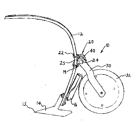
ABSTRACT
An improved packer apparatus in which the means of applying
pressure downwards on the packer wheel, a coil spring in the example, is at
the point of pivotal attachment of the wheel mounting bracket to the cultivator
shank. This allows the packer assembly to be very compact and have few
moving parts, and in consequence it causes no interference to the shank
when an obstruction is struck, is in less danger of breakage, does not exert
upwards pressure on the shank, and has greater freedom of movement than
earlier packer assemblies. The described example can also allow for varying
the packing pressure by reversing the spring or connecting the wheel
mounting bracket through a different hole in the bracket, or both. A neoprene
bushing ensures trouble-free, grease-free maintenance of the one only
moving part in the attachment/pivot assembly.
Note: Claims are shown in the official language in which they were submitted.
Note: Descriptions are shown in the official language in which they were submitted.
2024-08-01:As part of the Next Generation Patents (NGP) transition, the Canadian Patents Database (CPD) now contains a more detailed Event History, which replicates the Event Log of our new back-office solution.
Please note that "Inactive:" events refers to events no longer in use in our new back-office solution.
For a clearer understanding of the status of the application/patent presented on this page, the site Disclaimer , as well as the definitions for Patent , Event History , Maintenance Fee and Payment History should be consulted.
| Description | Date |
|---|---|
| Inactive: IPC from MCD | 2006-03-11 |
| Time Limit for Reversal Expired | 2000-03-27 |
| Application Not Reinstated by Deadline | 2000-03-27 |
| Deemed Abandoned - Failure to Respond to Maintenance Fee Notice | 1999-03-25 |
| Application Published (Open to Public Inspection) | 1994-09-26 |
| Abandonment Date | Reason | Reinstatement Date |
|---|---|---|
| 1999-03-25 |
The last payment was received on 1998-03-25
Note : If the full payment has not been received on or before the date indicated, a further fee may be required which may be one of the following
Patent fees are adjusted on the 1st of January every year. The amounts above are the current amounts if received by December 31 of the current year.
Please refer to the CIPO
Patent Fees
web page to see all current fee amounts.
| Fee Type | Anniversary Year | Due Date | Paid Date |
|---|---|---|---|
| MF (application, 5th anniv.) - small | 05 | 1998-03-25 | 1998-03-25 |
Note: Records showing the ownership history in alphabetical order.
| Current Owners on Record |
|---|
| RICK PROSKO |
| JAMES SOWA |
| Past Owners on Record |
|---|
| None |

