Sélection de la langue

Search

Sommaire du brevet 2092465 

Énoncé de désistement de responsabilité concernant l'information provenant de tiers

Une partie des informations de ce site Web a été fournie par des sources externes. Le gouvernement du Canada n'assume aucune responsabilité concernant la précision, l'actualité ou la fiabilité des informations fournies par les sources externes. Les utilisateurs qui désirent employer cette information devraient consulter directement la source des informations. Le contenu fourni par les sources externes n'est pas assujetti aux exigences sur les langues officielles, la protection des renseignements personnels et l'accessibilité.

Disponibilité de l'Abrégé et des Revendications

L'apparition de différences dans le texte et l'image des Revendications et de l'Abrégé dépend du moment auquel le document est publié. Les textes des Revendications et de l'Abrégé sont affichés :

  • lorsque la demande peut être examinée par le public;
  • lorsque le brevet est émis (délivrance).
(12) Demande de brevet: (11) CA 2092465
(54) Titre français: ENSEMBLE DE MISE EN BALLES FIXE AU BRAS DE CULTIVATEUR
(54) Titre anglais: SHANK-ATTACHED PACKER ASSEMBLY
Statut: Réputée abandonnée et au-delà du délai pour le rétablissement - en attente de la réponse à l’avis de communication rejetée
Données bibliographiques
Abrégés

Abrégé anglais


ABSTRACT
An improved packer apparatus in which the means of applying
pressure downwards on the packer wheel, a coil spring in the example, is at
the point of pivotal attachment of the wheel mounting bracket to the cultivator
shank. This allows the packer assembly to be very compact and have few
moving parts, and in consequence it causes no interference to the shank
when an obstruction is struck, is in less danger of breakage, does not exert
upwards pressure on the shank, and has greater freedom of movement than
earlier packer assemblies. The described example can also allow for varying
the packing pressure by reversing the spring or connecting the wheel
mounting bracket through a different hole in the bracket, or both. A neoprene
bushing ensures trouble-free, grease-free maintenance of the one only
moving part in the attachment/pivot assembly.

Revendications

Note : Les revendications sont présentées dans la langue officielle dans laquelle elles ont été soumises.


CLAIMS
The embodiments of the Invention in which an exclusive property or
privilege is claimed are defined as follows:
1. A packer apparatus to pack earth behind a cultivator shank,
consisting of:
a packer wheel;
a wheel mounting bracket attached at one end to the wheel;
pivot means of pivotally attaching the wheel mounting bracket
to the shank; and
means of applying pressure downwards on the wheel mounting
bracket at or very near the place where said pivot means attaches the bracket to the
shank;
whereby the mounting bracket is attached to and pulled by the
shank, and whereby pressure is exerted on the bracket, and hence on the packing
wheel, in order to pack earth behind the shank.
2. An apparatus as in Claim 1, in which the means of applying
pressure is a spring wound around the longitudinal axis of the pivot means.
3. An apparatus as in Claim 2, in which there is user-choosable
means to vary the pressure applied to the packer wheel.
4. An apparatus as in Claim 2, in which the user may vary the
pressure by reversing the spring.
5. An apparatus as in Claim 3, in which the user may vary the
pressure by changing the place at which the mounting bracket is attached to the pivot
means.
6. An apparatus as in Claim 1, in which there is an airseeder
attached to the shank, and the packer wheel packs earth on top of a seed deposited by
the airseeder.
7. An apparatus for packing earth behind a cultivator shank,

consisting of:
a packer wheel;
a wheel mounting bracket attached at one end to the wheel and
with a hole through the other; and
a bracket attachment mechanism to pivotally attach said other
end of the wheel mounting bracket to the shank; said mechanism consisting of:
a plate with four holes;
2 U-clamps to fit through the holes and around the front
of the shank;
2 flanges extending backwards from the plate;
a flange hole in each flange;
a pin to fit through the flange holes and the hole in the
mounting bracket;
a neoprene bushing to cover the pin between the
flanges;
a pipe to cover the bushing; and
a coil spring around the pipe, braced against the plate
on one end and the bracket on the other;
whereby the packer wheel mounting bracket is pivotally
attached to and pulled by the shank, and whereby pressure is exerted on the bracket
by the coil spring, and hence on the packing wheel, in order to pack earth behind the
shank.
8. An apparatus as in Claim 7, in which there is an airseeder
attached to the shank, and the packer wheel packs earth on top of a seed deposited by
the airseeder.
9. An apparatus as in Claim 7, in which the pressure applied can
be varied by having a coil spring of less or more coils.
10. An apparatus as in Claim 7, in which the ends of the spring are

offset different amounts from the longitudinal axis of the spring, so that pressure can
be varied by the user by reversing the spring.
11. An apparatus as in Claim 10, in which there is more than one
hole in the bracket to allow the bracket to be affixed to the bracket attachmentmechanism at different places, thus allowing the pressure to be further varied by the
12. An apparatus as in Claim 7, in which the plate is curved to
match the curvature of the shank.
13. An apparatus as in Claim 7, in which the plate, bracket, pipe,
and pin are made of steel; the plate is 1/2" thick by 4" high by 4 1/2" wide; the flanges
extend from 1 1/2" to 3" from the plate; the pipe is 4" interior diameter; and the
bracket is connected to the packing wheel by a bracket pipe integral with the bracket
or welded there, of 2 1/64" interior diameter.

Description

Note : Les descriptions sont présentées dans la langue officielle dans laquelle elles ont été soumises.

~ ` 2092~6~
INTRODUCTION AND DeSCRlPrlON OF THE PRIOR ART
The invention to be described is a new type of packer assembly for
automatic seeding systems, and is appropriate for all sorts of airseeders. As with
previous packers, there is a packer wheel attached to the shank; but the invented
wheel has a different attachment configuration that allows for several advantages over
existing systems.
With present shank-mounted packers there is a mechanism for
applying pressure to the wheel that is separate from the pivot point between the wheel
and the shank. Problems arising from this include the following:
; (1) there isn't enough room between the pressure mechanism and the
frame of the cultivator; when the shank has to trip over an obstacle,
; it's not able to move all the way back without damaging the packer
~:'< assembly;
.j
ij (2) the springs used cause the mechanism to slide up on Ihe shank;
`1
(3) too complex; too many moving parts in the pressure mechanism--a
common complaint is that the assemblies fall off--;
(4) the spring pressure can't be varied enough, and various soils nee(l
widely different amounts of pressure;
(5) high maintenance: they must be greased or will wear out quickly
due to metal wearing on metal;
(6) the wheel is mounted so far behind the shank that when the shank
~' is tripping over an obstacle the obstacle strikes directly on the
packer wheel causing it ~o break off;
(7) the packer has a limited amount of movement;
. (8) they aren't readily adaptable to all airseeders;
(9) the assembly is cumbersome, yet not easy to remove should you
desire to have no packer; and
( 10) most use a cast formed shank mould. and as a re~sult they break
,.~
'~i
., . . -: , . , :: . : : . .

~ 209246S
off.
On a review of this list, it will be immediately apparent that a new type
of assembly is in order. The invented one has these advantages:
(I) the sprhlg and pivot point are together as one, making it very
compact and causing no interference with the trip mechanism of
the shank;
(2) because the spring and pivot are together there is no upward
pressure from the packer wheel to the shank, but rather a twisting
motion, so the pressure mechanism will not slide up the shank;
(3) simplicity: there is only one moving part which has a neoprene
bushing not needing lubrication;
(4) four different pressure settings are possible for the packing wheel,
by permutations of an extra hole in the wheel mounting bracket
and the slight offset of the spring con~act points, which can be
reversed to give different pressure;
(5) as the shank trips over an obstacle the wheel moves ahead and
downwards and hits the obstacle at a point where it is under no
pressure, then simply rolls with the obstacle back into packing
position;
(6) the spring mounting allows free movement of the assembly;
(7) because of compact design, the assembly is easily adaptable to any
airseeder;
(8) the assembly is quickly and easily removed by taking one pin out;
(9) due to simplicity it's very low in maintenance and very durable;
and
(10) mounting and brackets are made of steel and will not break easily.
DETAILED DESCRIPTION OF THE INVENTION
~rr~ `, . . . "" ~ J, ,,-" ,,"",~ ~ ","~ ","~ ," ~ ," ~ " , ~
.. . .. . . .. . ~ ~ . . ~

2092465
For this description, ret`er lo the following diagrams, wherein like
numerals refer to like parts:
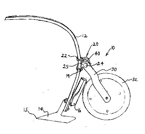
Figure 1, illustrated embodiment of the invented packer assembly in
usage position Oll shank; perspective view;
Figure 2, the illustrated embodiment; top plan view;
Figure 3, the illustrated embodiment; rear elevation;
Figure 4A, attachment plate of the illustrated embodiment; rear
elevation;
Figure 4B, attachment plate of the illustrated embodiment; side
elevation;
Figure 4C, attachment plate of the illustrated embodiment, with U-
ql clamp; top view; and
Figure 5, further usage situation of the ilhlstrated embodiment of theinvented packer assembly, with cultivator blade striking obstruction; perspective
.~
The invented packer assembly indicated as lO on Figure l is attached
to shank 12 bearing blade 14 and airseeder 16 by attachment mechanism generally
indicated as 20. U-clamps 22 surround shank 12, while flange 25 has pin 24 insened
through it and through wheel mounting bracket 30 extending to wheel 32. This will be
!~ better understood with reference to Figure 2, where assembly lO is seen in top plan : -:
without shank 12; bracket 30 attaches to wheel bearing 34 by means of a bracket pipe
3 33, characteristically heavy wall pipe Of 21/64" I.D.. Spring 40 coils around spring
pipe 42, characteristically heavy wall of 4" l.D., bracing between plate 19 and
3 mounting bracket 30. A neoprene bushing, not visible, is placed between spring pipe
42 and pin 24. Figure 3 affords a rear elevation view of the assembly 10, with ~he
addition of nuts 50 securing the U-clamps 22. Note that in Figure 3 the spring 40 has
less coils than in Figure 2; other different springs with more or less coils (not
illustrated) could t imilnrly be provided to apply ditferent Imoun~i of preisure.
$

~ 209246S
Figures 4A, 4B, and 4C show more clearly the plate 19, characteristically 1/2" thic!c
by 4 " high by 4112 " wide, and having four 1/2 " diameter holes 18 for the U-clamps
22 (not shown in Figures 4A or 4B). Dual flanges 25 extending from plate 19 are
characteristically 11/2" high, 1/2'' itl thickness, and extend anywhere from 1]/2 to 3"
from plate 19, depending on the size of mounting bracket (not shown) being
accommodated. Holes 26 are characteristically of 3/4" diameter; pin 24, seen on
Figures 1, 2, and 3, is fit through holes 26. Note the curvature of plate 19, visible
,.
most clearly on Figure 4B; this matches the curvature of shank 12 (as seen on Figure
1) at the portion of shank 12 where assembly 10 is attached.
The assembly 10 is illustrated in action in Figure S, where blade 14,
travelling in direction of point lS, has risen over obstruction 100. It can be easily seen
, .
that assembly 10, attached as it is to shank 12, merely rises also and will bounce off
obstruction 11)0 without trouble. Multiple packer assemblies 10 and shanks 12 will
usually be attached in parallel to a cultivator frame 200. although ~hese are not shown
on Figure S. During unobstructed use, which Pigure I can be taken to illustrate, spring
40 merely presses on bracket 30, which is welded to or integral with bracket pipe 33
(seen on Figure 2), and so presses wheel 32 downwards to pack earth (not shown) on
row (not shown) containing seed (not shown) deposited by airseeder 16 after blade 14
has opened a row. As mentioned, the amount of this pressure can be varied by having
different numbers of coils on spring 40, or--for any given spring--by reversing the
~, spring or by attaching the mounting bracket 30 by different holes (reversing and
different holes options are not illustrated).
`~ An object of the present invention is to provide for an apparatu~ as
described in which the means of applying pressure is a spring wound around the
longitudinal axis of the pivot means.
The foregoing is by example only, and the scope of the invention
should be limited only by the appended claims.
:

Dessin représentatif
Une figure unique qui représente un dessin illustrant l'invention.
États administratifs

2024-08-01 : Dans le cadre de la transition vers les Brevets de nouvelle génération (BNG), la base de données sur les brevets canadiens (BDBC) contient désormais un Historique d'événement plus détaillé, qui reproduit le Journal des événements de notre nouvelle solution interne.

Veuillez noter que les événements débutant par « Inactive : » se réfèrent à des événements qui ne sont plus utilisés dans notre nouvelle solution interne.

Pour une meilleure compréhension de l'état de la demande ou brevet qui figure sur cette page, la rubrique Mise en garde , et les descriptions de Brevet , Historique d'événement , Taxes périodiques et Historique des paiements devraient être consultées.

Historique d'événement

Description Date
Inactive : CIB de MCD 2006-03-11
Le délai pour l'annulation est expiré 2000-03-27
Demande non rétablie avant l'échéance 2000-03-27
Réputée abandonnée - omission de répondre à un avis sur les taxes pour le maintien en état 1999-03-25
Demande publiée (accessible au public) 1994-09-26

Historique d'abandonnement

Date d'abandonnement Raison Date de rétablissement
1999-03-25

Taxes périodiques

Le dernier paiement a été reçu le 1998-03-25

Avis : Si le paiement en totalité n'a pas été reçu au plus tard à la date indiquée, une taxe supplémentaire peut être imposée, soit une des taxes suivantes :

  • taxe de rétablissement ;
  • taxe pour paiement en souffrance ; ou
  • taxe additionnelle pour le renversement d'une péremption réputée.

Les taxes sur les brevets sont ajustées au 1er janvier de chaque année. Les montants ci-dessus sont les montants actuels s'ils sont reçus au plus tard le 31 décembre de l'année en cours.
Veuillez vous référer à la page web des taxes sur les brevets de l'OPIC pour voir tous les montants actuels des taxes.

Historique des taxes

Type de taxes Anniversaire Échéance Date payée
TM (demande, 5e anniv.) - petite 05 1998-03-25 1998-03-25
Titulaires au dossier

Les titulaires actuels et antérieures au dossier sont affichés en ordre alphabétique.

Titulaires actuels au dossier
RICK PROSKO
JAMES SOWA
Titulaires antérieures au dossier
S.O.
Les propriétaires antérieurs qui ne figurent pas dans la liste des « Propriétaires au dossier » apparaîtront dans d'autres documents au dossier.
Documents

Pour visionner les fichiers sélectionnés, entrer le code reCAPTCHA :


Pour visualiser une image, cliquer sur un lien dans la colonne description du document. Pour télécharger l'image (les images), cliquer l'une ou plusieurs cases à cocher dans la première colonne et ensuite cliquer sur le bouton "Télécharger sélection en format PDF (archive Zip)" ou le bouton "Télécharger sélection (en un fichier PDF fusionné)".

Liste des documents de brevet publiés et non publiés sur la BDBC .

Si vous avez des difficultés à accéder au contenu, veuillez communiquer avec le Centre de services à la clientèle au 1-866-997-1936, ou envoyer un courriel au Centre de service à la clientèle de l'OPIC.


Description du
Document 
Date
(aaaa-mm-jj) 
Nombre de pages   Taille de l'image (Ko) 
Revendications 1994-09-25 3 111
Abrégé 1994-09-25 1 28
Dessins 1994-09-25 5 162
Description 1994-09-25 4 184
Dessin représentatif 1998-08-09 1 11
Courtoisie - Lettre d'abandon (taxe de maintien en état) 1999-04-21 1 187
Rappel - requête d'examen 1999-11-28 1 117
Taxes 1998-03-24 1 49
Taxes 1997-03-24 1 42
Taxes 1996-03-20 1 40
Taxes 1995-03-22 1 45