Note: Descriptions are shown in the official language in which they were submitted.
2~92883
The invention relate~ to improvement~ in device~
for the application of preselected torque to rotary parts,
particularly to ~crew~, nutQ, boltQ and other externally
or internally threaded fa~tenerQ. For example, deviceq of
the type to which the pre~ent invention pertain~ can be
utilized with advantage for the application of a
preselected torque to tightening ~crew~ in hoQe clamp~ and
the like.
It iQ already known to provide a device which
can be applied to the head of a ~crew or another threaded
fa~tener and can be rotated by a wrench, by a ~crew driver
or by another 3uitable tool in order to rotate the
faQtener until the fastener begin~ to offer a pre~elected
reqiQtance to further rotation. Reference may be had, for
example, to commonly owned U.S. Pat. No. 5,176,050 granted
January 5, 1993 to Heinz Sauer for "Tool for the
application of predetermined torque to bolt~, nut~ and the
like." The device of Sauer compri~eQ a firQt ~ection
which can be permanently affixed to the head of a qcrew
and a ~econd Qection which become~ Qeparated from the
fir~t section in response to the application of a
preQelected torque by a wrench or by another Quitable
tool, namely when the ~crew begins to offer a
predetermined re~i~tance to further rotation. Separation
of the second portion from the firQt portion of the device
which i~ di~clo~ed by Sauer et al. con~titute~ evidence
that the screw wa~ driven home in re~pon~e to the
application of a preselected torque, namely a torque which
was neces~ary to separate the ~econd section from the
fir~t ~ection. However, an unauthorized perQon is not
- 2 - ~
2o9~886~
prevented from rotating the ~crew in a direction to drive
the ~crew deeper into one or more object~ or to loo~en the
screw. In other words, the device of Sauer can furniqh
evidence that a preselected force wa~ indeed applied to
drive the nut home but ~uch device cannot indicate whether
or not the ~crew has been tampered with Qub~equent to
separation of the second ~ection from the fir~t ~ection.
A~ a rule, the head of the 3crew ha~ a polygonal or
otherwise configurated internal ~urface which can be
engaged by the working end of a suitable tool (quch aq a
~crew driver or a tool having a polygonal working end
insertable into a complementary socket in the head of a
~crew) to be rotated ~ub~equent to separation of the
qecond ~ection from the first section of the device which
i~ disclo~ed by Sauer et al. Furthermore, and ~ince the
fir~t section iq non-rotatably secured to the head of the
Qcrew, and if ~uch first section i~ provided with a
polygonal, oval or other non-circular external ~urface,
the ~crew can be driven deeper into one or more object~ or
can be loosened by a tool which i~ used to engage the
external ~urface and to thereupon rotate the firQt ~ection
of the device ~ub~equent to separation of the second
~ection.
If the device of Sauer i~ utilized in a motor
vehicle and a Qcrew or another rotary part i~ either
loo~ened or driven home with an exces~ive force, the maker
of the vehicle or a per~on in charge of repairing the
vehicle can prove that, by having utilized the device of
Sauer, the rotary part WaQ driven home in re~pon~e to the
application of a pre~cribed (preselected) torque.
21)92883
However, thiq doe~ not ~uffice to relieve the maker or the
repairman of re~ponYibility for loo~ening or exceqqive
application of the rotary part qubsequent to the
application of a pre~elected torque with the device of
Sauer. Thi~ can re~ult in a controver~y and the maker of
the vehicle and/or the person in charge of repairing the
vehicle might be liable for damage~ to and for repair of
the vehicle under an exi~ting warranty or at quch perqon'~
own expense.
German Au~lege~chrift No. 1 134 252 of Heil
(published AuguQt 2, 1962) disclo~es a screw with two
coaxial heads which are dispo~ed end-to-end and one of
which i~ of one piece with the externally threaded shank
of the ~crew. The other head become~ ~eparated from the
one head in respon~e to the application of a pre~elected
torque by a ~crew driver or an analogou~ tool. The one
head iQ confined in a socket which iq installed in one of
the object~ to be connected to each other by the qhank of
the properly applied screw, and the ~ocket iq thereupon
filled, e.g., with an insert con~i~ting of lead, when the
~eparation of the other head i~ completed. Ab~ence of the
in3ert or visible damage to the in~ert con~titute~
evidence that the device ha~ been tampered with subqequent
to -qeparation of the other head from the one head and
~ub~equent to filling of the ~ocket with an insert of
lead. The one head i-Q devoid of slot~ or like
configurationq which would permit engagement by a screw
driver, by a wrench or by any other ~uitable tool for the
purpose of loo~ening or withdrawing the ~crew sub~equent
to removal of the insert from it3 socket. Therefore, the
2as2ss3
inventor propoqe~ to form ~lot~ in the one head after
removal of the in~ert QO that the thu~ shaped one head can
be engaged by a ~uitable implement and loo~ened or
withdrawn from the part or part~ which receive the ~hank
of the ~crew. A drawback of the device of Heil i~ that
the twin-headed screw i~ not a ~tandard ~crew, that the
device muqt employ an accurately machined or otherwise
finiqhed socket, that the application of an in~ert of lead
takes up much time, that the removal of the in~ert take~
up much time, and that the one head mu~t be treated
~ub~equent to removal of the insert in order to permit
engagement of the one head by a ~uitable tool which i~ to
loosen or remove the screw.
German Utility Model No. 90 11 571.6 of Petri
(publi~hed February 14, 1991) di~closes a device wherein
one end face of a headless ~crew i~ provided with a
polygonal rece~. The one end face is of one piece with
one axial end of a tubular neck ~ection which, in turn, i~
of one piece with a hexagonal ~econd ~ection. The aligned
axial pa~qageq of the two section~ contain a ma~ of
compacted ~teel wool, felt, foamed plastic or the like in
order to prevent acce~s to the rece~ of the ~crew while
the latter i~ qtill of one piece with the two ~ection~.
TheQe sections can be ~eparated from the Qcrew at the end
face in re~pon~e to the application of a pre~elected
torque, and thiQ immediately affords acce~ to the rece~
in the end face of the screw, i.e., the ~crew can be
tampered with ~ub~equent to the application of a
preselected torque a~ evidenced by ~eparation of the two
sections from the end face of the qcrew. Thu~, the device
2~92883
of Petri alqo fails to prevent tampering with a rotary
part subsequent to the application of a preselected
torque.
U.S. Pat. No. 4,037,515 granted July 26, 1977 to
Kesselman di~closeq a tamper resistant fa-qtener wherein a
~tud engaging portion of ~teel can be applied over an
externally threaded stud and becomeq separated from a
hexagonal wrench engaging portion in responqe to the
application of a preselected torque to the hexagonal
portion. The stud engaging portion i~ ~urrounded by a
81ip ring which is freely rotatable thereon and has a
cylindrical external surface 80 that it cannot be rotated
by a -qtandard wrench or by a like implement. The narrow
clearance between the slip ring and the stud can be
overlapped by a flange of the slip ring to thuq prevent
the insertion of a jamming tool between the split ring and
the stud. A drawback of the patented fa~tener is that the
qtud cannot be readily rotated once the hexagonal portion
i~ broken off the stud engaging portion, and that the ~lip
ring muqt be machined or otherwiqe treated and in~talled
with a high degree of accuracy.
The invention re~ide~ in the provi~ion of a
device which can be u-~ed to apply a pre~elected torque to
a rotary part having an end portion with an internal
surface engageable by a torque transmitting tool. The
improved device comprises or constitutes an adapter
including a tubular first section non-rotatably
surrounding the end portion and having an external surface
devoid of any disengaging tool accommodating means, a
second section which is adjacent the first section and has
2092883
at least one surface engageable by a torque transmltting tool,
a iolnt which connects the sectlons and permlts separatlon of
the sectlons from each other ln response to the appllcatlon of
the preselected torque to the second sectlon, and a
destructlble barrler ln the first section between the end
portlon and the ~olnt, whereln sald barrler lncludes a
dlaphragm whlch ls penetrable by an lmplement ~such as a
wrench or a screw drlver) to afford access to the lnternal
surface of the end portlon of the rotary part.
The ~olnt can be of one plece wlth the two sectlons
of the adapter.
The adapter can be provlded wlth an external groove
whlch surrounds the ~olnt and is bounded by mutually incllned
external surfaces of the two sections. Such mutually incllned
surfaces can make an acute angle.
The flrst sectlon can be of one plece wlth the end
portion of the rotary part. Alternatlvely, the flrst sectlon
can be bonded to the end portion of the rotary part or it can
be in frictional engagement wlth the end portlon.
The barrier is or can be of one plece with the first
section of the adapter. The latter can be made (either
entirely or in part) of a plastic material.
The at least one surface of the second section of
the improved adapter can be a polygonal (e.g., hexagonal)
external surface.
The external surface of the first section can be a
cylindrlcal surface.
24732-67
21392883
The novel feature~ which are con~idered aQ
characteri~tic of the invention are qet forth in
particular in the appended claims. The improved device
it-qelf, however, both aq to its conQtruction and the mode
of using the -qame, together with additional features and
advantageQ thereof, will be best understood upon perusal
of the following detailed description of certain presently
preferred ~pecific embodiments with reference to the
accompanying drawings.
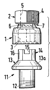
FIG. 1 i~ a side elevational view of an adapter
which embodie~ the invention;
FIG. 2 is a top plan view of the adapter;
FIG. 3 is a bottom plan view of the adapter;
FIG. 4 is an enlarged view of a detail within
the phantom-line circle IV in FIG. 1;
FIG. 5 illustrates the adapter of FIG. 1 and a
rotary part prior to attachment of the fir~t section of
the adapter to the end portion of the rotary part; and
FIG. 6 illuQtrate~ the ~tructure of FIG. 5
subsequent to attachment of the first ~ection of the
adapter to the end portion of the rotary part.
The improved device is an adapter including a
tubular firQt section 1, a tubular second Qection 2, a
breakable joint 7 which connect~ the sectionQ 1, 2 to each
other, and a deQtructible barrier in the form of a flat
diaphragm 6 extending acroqs the internal passage of the
qection 1 adjacent the joint 7. The entire adapter is or
can be made of a suitable plastic material in such a way
that the joint 7 i8 of one piece with the sectionQ 1 and
2. The ~ection 1 has a hexagonal internal Qurface 3 which
-- 8 --
2~9~83
extend~ from the free end of this Qection clo~e to the
barrier 6, and a largely cylindrical external qurface la
which iq devoid of any disengaging tool accommodating
mean~. In other words, the ~urface la i~ ~elected in ~uch
a way that it cannot be readily engaged by a wrench or by
another standard tool for the purpo~e of rotating the
~ection 1 and the end portion or head 13 of a rotary part
11 of the type ~hown in FIGS. 5 and 6. The illu~trated
surface la include-Y a cylindrical portion adjacent the
free end of the section 1, a qlightly conical portion
adjacent the cylindrical portion, a ~ub~tantially radial
~houlder 8 adjacent the slightly conical portion and a
more pronounced conical portion 9 adjacent the ~ection 2.
The radius of curvature of gradual tranqition from the
~houlder 8 into the more pronounced conical portion 9 of
the external Qurface la i~ indicated at R.
The ~econd section 2 of the improved adapter ha~
a polygonal (normally hexagonal) external ~urface 4 which
can be readily engaged by a suitable wrench or by another
torque transmitting tool to apply to the ~ection 2 a
pre~elected torque at which the joint 7 i~ de~troyed ~o
that the ~ection 2 becomes ~eparated from the Qection 1.
The pre~elected torque is effective to entail a
de~truction of the joint 7 when the externally threaded
~hank or ~tem 12 of the rotary part 11 offer~ a
predetermined re~i~tance to further penetration into an
object or to further di~placement relative to one or more
objects. The ~ection 2 may but need not be provided with
an axial pa~age 5, and the pa~age may but need not be
bounded by a non-circular surface (in lieu of the
2~92883
illuQtrated cylindrical internal ~urface) ~o a-~ to enable
a different torque tran-~mitting tool to engage and rotate
the qection~ 1, 2, until the joint 7 i~ deQtroyed, by
introducing the working end of ~uch tool into the pa~age
5. If provided, the pa~sage 5 afford~ acceq~ to the
barrier 6 in the ~ection 1.
The barrier 6 can have a ne~ligible thickne~
e.g., in the range of a fraction of one millimeter (for
example, 0.3 mm) ~o that it can be readily de~troyed by
the working end of a qcrew driver, by a wrench or by any
other ~uitable implement, particularly upon deqtruction of
the joint 7 ~o that the barrier 6 i~ acce-~ible at that
end of the ~ection 1 which wa~ previou~ly of one piece
with the ~ection 2.
The adapter is or can be relatively ~mall. For
example, the ~ize of an adapter of the type ~hown in FIGS.
1 to 3 can be approximately five time~ the actual ~ize of
a ma~s produced adapter.
The joint 7 is surrounded by a pronounced
circumferentially complete groove which iQ bounded by two
mutually inclined surfaceq, namely a radially extending
shoulder 10 of the second section 2 and the aforementioned
pronouncedly conical portion 9 of the external ~urface la
of the fir-~t ~ection 1. The ~houlder 10 and the conical
portion 9 of the ~urface la make an acute angle alpha (qee
particularly FIG. 4), e.g., an angle in the range of 70.
The just de~cribed configuration of the ~urfaces bounding
the groove around the joint 7 en~ure~ that the joint
break~ at the ~houlder 10, i.e., at a predetermined
location close to the barrier 6 in the axial passage of
-- 10 --
2092883
the qection 1. Exact advance determination of the locu~
of break between the section~ 1 and 2 i~ de~irable and
advantageou~ because thi~ en~ure~ that the barrier 6 i~
not damaged or de~troyed when the joint 7 breaks and al~o
that the barrier 6 i~ clo~e to the re~pective end of the
section 1 a~ Qoon a-~ the section 2 i~ detached -~o that the
barrier 6 can be readily engaged and at lea~t partially
destroyed or removed by a readily available tool or
implement.
The rotary part 11 which i~ illu~trated in FIGS.
5 and 6 i~ a ~crew having the aforementioned external
threaded ~hank or stem 12 and the end portion or head 13
including a fruqtoconical portion 13a of one piece with
the shank 12 and a ~econd portion 14 which i~ of one piece
with the fruQtoconical portion 13a. The portion 14 has a
polygonal (e.g., hexagonal) external ~urface 16 which can
be non-rotatably received in the passage ~urrounded by the
internal ~urface 3 of the section 1, and a diametrically
extending ~lot 15 bounded by an internal ~urface which can
be engaged by the working end of a ~crew driver or another
~uitable tool.
When the adapter of FIGS. 1 to 3 i~ to be put to
u~e, it i~ moved from the po~ition of FIG. 5 to the
poQition of FIG. 6 ~o that the internal ~urface 3 of the
~ection 1 non-rotatably engage~ the external ~urface 16 of
portion 14 of the end portion or head 13 of the rotary
part 11. Thi~ en~ures that the rotary part 11 mu~t ~hare
the angular movements of the adapter. The adapter is then
rotated by a tool (not ~hown) which engage~ the polygonal
external surface 4 and/or the internal ~urface bounding
20928~3
the paqsage 5 of the section 2, and the qection 2
continues to tran~mit torque to the rotary part 11 through
the section 1 as long as the joint 7 remain~ intact. When
the joint 7 breakq in re~ponse to the application of a
pre~elected torque to the section 2, the latter become~
separated from the ~ection 1 and the barrier 6 iq expoQed.
It i~ deqirable to coat the internal qurface 3 in the
section 1 and/or the external qurface 16 with a -~uitable
adheqive which bonds the section 1 to the end portion or
head 13 so that the Yection 1 iq not ~eparable from the
end portion 13 when the de~truction of the joint 7 is
completed. Thi~ ensures that an unauthorized per~on
cannot qimply qlip the section 1 off the portion 14 of the
head 13 and to thereupon employ a tool in order to engage
the external surface 16 and/or the internal Qurface
bounding the ~lot 15 and rotate the rotary part 11
relative to the object or object~ which are engaged by the
externally threaded shank 12. InQtead, the qlot 15 iq
acce~ible only upon deqtruction of the barrier 6 (e.g.,
with the working end of a screw driver) ~o that the qlot
15 can be reached from that end of the ~ection 1 which was
of one piece with the qection 2.
The mean~ for applying a pre~elected torque to
the rotary part 11 for the purpo-qe of driving the rotary
part home and of deqtroying the joint 7 can include an end
wrench or spanner, a box wrench or a wrench with an
exchangeable working end, a~ long aq the ~elected tool can
properly engage the polygonal external surface 4 and/or
the internal surface of the section 2. The pre-~elected
torque is selected with a view to ensure that the rotary
- 12 -
2092~83
part 11 iq driven home or i~ otherwi~e applied with a
predetermined force, e.g., to properly secure a ho~e clamp
which iQ to connect a nipple or another tubular part to
one end of a flexible hoqe or the like.
A~ already mentioned above, an ob~erver of the
adapter (or more specifically of the remnant of the
adapter on the rotary part 11) can a~certain at a glance
that the rotary part 11 wa~ driven home in re~pon~e to the
application of a preselected torque (becau~e the joint 7
i~ de~troyed and the ~ection 2 i~ no longer of one piece
with the section 1 (or the ~ection 2 cannot be found at
all). Furthermore, a per~on looking at the remnant of the
improved adapter can ascertain whether or not the rotary
part 11 wa~ tampered with Qub~equent to separation of the
section 2 from the section 1. ThiQ can be a-~certained by
looking at the barrier 6; if the barrier i~ intact, the
rotary part 11 wa~ not rotated Qub~equent to separation of
the ~ection 2 from the section 1.
The condition of the adapter and of the rotary
part 11 can be a~certained even more readily if the
section~ 1, 2 are of different color~ and/or if the
barrier 6 and the other portion~ of the ~ection 1 are
differently colored. Thu~, a perqon wi~hing to in~pect
the condition of the rotary part 11 mu~t merely look for a
certain color (of the section 2) in order to ascertain
whether or not the ~ection 2 i~ ~till of one piece with
the section 1 (i.e., whether or not the rotary part 11 wa~
driven home in response to the application of a
preselected torque), and the condition (integrity or lack
of integrity) of the barrier 6 can be even more readily
- 13 -
~092883
a~certained if the color or hue of thi~ barrier depart~
from the color or color-~ of the other portion-~ of the
Qection 1.
Once the Qection 2 is separated from the ~ection
1, the portion 14 of the rotary part 11 can be reached
only upon de~truction of the barrier 6 or upon separation
of the ~ection 1 from the portion 14. However, and ~ince
the external ~urface la of the section 1 i~ conical and/or
cylindrical, it cannot be readily grasped by a di~engaging
tool. If a tool has been used to remove the ~ection 1
from the portion 14 of the rotary part 11, the external
surface la will exhibit markq which are indicative or
sugge~tive of tampering or attempted tampering.
Furthermore, the section 1 is preferably bonded to the
portion 14 ~o that they cannot be separated from each
other once the applied bonding agent i~ permitted to ~et.
In other wordQ, the only way to gain acce~ to the ~lot 15
of the portion 14 i~ to de~troy the barrier 6 which, in
turn, i~ indicative of tampering with the rotary part 11
~ubsequent to separation of the section 2 from the ~ection
1 of the improved adapter. Alternatively, de~truction of
the barrier 6 can be re~orted to by an authorized per~on
who mu~t gain acce~ to the qlot 15 in order to loo~en or
tighten the rotary part 11.
If the ~eparation or section 2 from the ~ection
1 ha~ taken place in the plant in which the rotary part 11
was driven home or was otherwise applied in re~pon~e to
the application of a preselected torque, any damage to the
barrier 6 i~ indicative of tampering with the rotary part
11 cubsequent to removal of the rotary part 11 from the
- 14 -
2092~83
plant. Therefore, a person claiming damage or injury due
to alleged application of insufficient torque to the
rotary part 11 i~ not likely to prevail in the event of a
diQpute with the owner of the plant or e~tabli~hment in
which the joint 7 between the sectionq 1 and 2 of the
improved adapter was deQtroyed. Thiq can be of importance
to the maker~ of automotive vehicleQ if the adapter iQ
used to driven home a screw under the hood of or el~ewhere
in a motor vehicle.
The step of adheQively bonding the internal
~urface of the section 1 to the external ~urface of the
end portion or head 13 of the rotary part 11 can be
omitted if the Qection 1 iq made of one piece with the end
portion 13. ThiQ can be achieved by resorting to an
extru~ion or injection molding technique in order to turn
out rotary part~ which are of one piece with ~ections 1, 2
and the sectionQ 2 are ~eparable from the qection~ 1 in
re~pon~e to the application of a pre~elected torque, all
aQ already deQcribed hereinabove.
It i~ further possible to e~tablish a
practically non-separable connection between a Qection 1
and the head of a -Qcrew or another rotary part by
eqtabli~hing a pre~ fit or another pronounced fit which
doe~ not permit separation of the Qection 1 from the head
13 of a rotary part. For example, the ~ection 1 can be
shrunk onto the portion 14 of a head 13 to thu~ ensure
that the resulting connection iQ permanent even though the
qection 1 is not adhesively bonded to the rotary part.
Prior to the making of the improved adapter in
an extruding or another suitable machine for the purpo~e
2û92883
of making the section 1 of one piece with or of ~hrinking
the ~ection 1 onto the head 13, the slot 15 i~ preferably
filled with a ~uitable ela~tomeric material which prevent-
~penetration of flowable pla.~tic (the pre~ently preferred
material for the making of the adapter) into the ~lot 15.
However, the ela~tomeric in~ert which fill~ the ~lot 15
doe~ not prevent the in~ertion of the working end of a
~crew driver or another ~uitable tool for the purpo~e of
rotating the part 11 ~ub~equent to separation of ~ection 2
from the section 1 and following de~truction of the
barrier 6 which affords acce~ to the ~lot 15.
It i~ further po~ible to replace the ~lot 15
with a non-circular ~ocket in the end face of the portion
14 or to employ the ~lot 15 in combination with a ~econd
~lot extending at right angle~ to the illuqtrated Qlot 15.
The portion 14 then exhibits a cruciform receqs for
reception of the working end of a standard ~crew driver or
for reception of a ~pecially designed (complementary
cruciform) working end of a torque tran~mitting tool which
is to be used to turn the part 11 sub~equent to at lea~t
partial de~truction of the barrier 6. A rotary part whose
end portion i~ provided with a cruciform slot or a like
rece~ for reception of a torque tranqmitting tool can
con~titute a ca~tellated nut. Thu~, the rotary part which
i~ to be rotated by re~orting to the improved adapter need
not alway-~ be provided with an external thread but can
al~o exhibit an internal thread.
An important advantage of the improved device is
that the tampering or ab~ence of tampering with the rotary
part can be immediately and reliably ascertained even by
- 16 -
2~92~83
an unskilled or semi~killed per~on. All that is nece~ary
iq to ascertain the presence or absence of the section 2
(thi~ indicate~ whether or not the rotary part wa~ driven
home in re~ponse to the application of a pre~cribed
(preselected) torque and to ob-qerve the condition of the
barrier 6 (and, if necessary or de~ired, the condition of
the external qurface la of the ~ection 1); thi~ enable~
the obqerver to ascertain whether or not the rotary part
(~uch a~ the illu~trated ~crew 11) ha~ been tampered with
(or whether or not an attempt to tamper with the rotary
part was made) sub~equent to ~eparation of the ~ection 2
from the section 1.
Another important advantage of the improved
device i~ that an authorized per~on can readily gain
acceQ~ to the ~lot 15 or an analogou~ rece~ in the end
portion 14 of a rotary part by the ~imple expedient of
de~troying the barrier 6.
A further important advantage of the improved
device i~ that the location of the joint 7 iq defined with
a requi~ite degree of accuracy ~o that the ~eparation of
the ~ection 2 from the section 1 take~ place clo~e to the
barrier 6 but the latter i-~ not deQtroyed or damaged a~ a
re~ult of ~eparation of the ~ections 1 and 2 from each
other.
An additional advantage of the improved device
i~ that the section~ 1 and 2 can be made of one piece.
Thi~ reduce~ the cost of the adapter and simplifie~
~torage of unu~ed adapter~ in an automobile assembling
plant or in any other establi~hment which employs the
improved adapter. However, it is equally within the
~92883
purview of the invention to e~tabli~h between the ~ection-
~1 and 2 a joint which is not of one piece with the Qection
1 and/or with the qection 2, as long a~ the joint permit~
separation of the ~ection 2 from the ~ection 1 upon
completed application of pre~elected torque to a rotary
part which receive~ torque from the section 1.