Note: Descriptions are shown in the official language in which they were submitted.
CA 02092934 2001-03-08
LIQ1JID HEATING APPARATUS
[ Background of the Invention ]
This invention relates to a liquid heating apparatus, such
as a boiler, utilizing an ascendant/descendant flowing system
of a combustion gas.
The liquid heating apparatuses as described above include,
for instance, one that this applicant proposed in Japanese
Utility Model Publication No. 15168/1956, and the apparatus is
as shown in FIGS. 1 and 2. In this apparatus, an internal drum
22 comprising a dual wall is arranged in and at a space from
an external drum 21 cc-_>mprising a dual wall. A combustion gas
descending chamber 23 :is provided therebetween. An outer water
chamber 26, having a hot water outlet port 24 and a watE:r inlet
port 25, in the upper and lower sections thereof respectively
is provided outside this combustion gas descending chamber 26.
An inner water chamber 27, in communication with the outer
water chamber 26 via the upper and lower communicating tubes
23, is provided inside the combustion gas descending chamber
23. A combustion chamber 29, in communication with the
combustion gas descending chamber 23 in the upper section
thereof, is provided in the internal drum 22. An exhaust port
is provided under the combustion gas descending chamber 23.
A flue 33 is in comnuunication w~th this exhaust port 30, and
a combustor 32 is detachably mounted through the inner and
outer water chambers 26 and 27. It should be noted that the
numeral 34 indicates a clearing port. In the liquid heating
apparatus as described above, the combustion gas successively
rated by the combustc>r 32 goes up in the combustion chamber 29,
30 the radiant heat being absorbed therein, and tr.en the
combustion is inverted in the upper section thereof and flows
down through the combustion gas descending chamber 23 at a flow
velocity g (m/sec), the flow velocity being increased to a
velocity G (m/sec) at the exhaust port 30, and is exhausted to
the flue 33. During this process, the combustion gas rapidly
1
CA 02092934 2001-03-08
raises temperature of t=he liquid by delivering the heat through
radiation or contact t~~ the liquid in the inner and outer water
chambers 26 and 27 and raising the heat exchange rate between
the combustion gas and the liquid, and at the same time the
descending fluidity i;~ raised and the combustion efficiency is
improved, so that incomplete combustion is advantageously
prevented.
Although the conventional type of liquid heating apparatus
provides the advantage as described above, :it has the following
problem: namely, thc; liquid heating apparatus as described
above has a flow path, fo:r a combustion gas in the combustion
gas descending chambc:m 23, which is narrow so that delivery of
heat. is efficientl~n carried out through contact by the
combustion gas. In other words:
(1) The combustion gas flowing down in the narrow flow
path flows laterally at a substantially right angle
with the flow velocity G as described above under
the exhaust port 30 via the flue 33 communicated to
the exhaust port 30, and furthermore flows upwardly
at substantially right angles outside the external
drum 21, thus an extremely large air exhaust
resistance is generated. This air exhaust
resistance prevents the combustion gas from flowing
smoothly, and the expected effect cannot be
achieved, which is a problem to be solved.
(2) If cross-sectional areas of the exhaust port. 30 and
the flue 33 are made larger to solve this problem,
i.e., by ~al.lowing a smooth flow of the combustion
gas to overcome the large exhaust resistance,
disturbance occurs at a flow velocity of V (m/sec)
from an exhaust port of the flue 33 as indicated by
the arrow mark in FIG. 2. If the relation between
the flow velocity V is higher than the flow velocity
G of the c.~o:nbustion gas (V < G) , normal combustion
is maintained, but in case of V > G, disturbance
2
CA 02092934 2001-03-08
occurs in the combustion chamber 29, which prevents
normal combustion. When fire occurs, the draft
power in the flue 33 is generally expressed by the
equation of Df ~ H x (Tgm - To) (wherein Df is draft
power, H is height, Tgm is an average temperature in
the flue 33, and To is a temperature of peripheral
air) . In the case of the flue 33 having a large
cross-sectional area, a quantity of heat radiated
from the surface of- thF: flue increases and th.e draft
power is Lost, giving a poor influence over
combustion. When combustion is stopped, external
air comes i_n from an opened exit of the flue 33,
having a large cross-sectional. area, which cools a
heat insulation gas residing in the apparatus and
generates convection therein. Then, the heat
insulation gas is exhausted via the flue 33 to the
outside and the temperature decreases. In such a
system, as an automatic hot water supply system, the
combustor 9 operates to restart unnecessary heating,
which results in a waste of energy and increase of
the running cost. Also, the combustion state in the
apparatus becomes so unstable as to interrupt
combustion in the combustor 32, or to generate
oscillating combustion, <~s well as to generate
noise. These are other problems to be solved.
[ Summary of the Invention ]
An object of the present invention is to so:Lve the
problems in the conventional type of liquid heating apparatuses
as described above by providing a liquid heating apparatus
wherein: a combustic:m gas can smooth--y flow without generating
a ,rarge exhaust resistance when the combustion gas is
exhausted; an external distu:rbanr_e can hardly come into a flue
from the exhaust port even if cross-sectional areas of the
exhaust port and the flue are not increased; and, accordingly,
3
CA 02092934 2001-03-08
an external disturbance does not enter the combustion gas
descending chamber, or the combustion chamber, to disturb the
combustion state or generate noise therein.
In order to achv..eve the obj ects as described above, there
is provided a liquid heating apparatus according to the present
invention wherein: yin internal drum is arranged in an external
drum; the internal drum consists of an external vessel,
intermediate vessel and internal vessel; the internal vessel
constitutes a combustion chamber; an outer water chamber is
formed between the external drum and the external vessel; a
combustion gas descending chamber is formed between the outer
vessel and the intermediate vessel; an inner water chamber is
formed between the intermediate vessel and internal vessel; a
hot water outlet port connecting the outer water chamber with
outside of the apparatus is provided at an upper section of the
external drum; a water supply port connecting the outer water
chamber with the outside of the apparatus is provided at the
lower section of the external drum; the combustion chamber is
in communication with the combust:ion gas descending chamber via
upper of communicating tubes and is also in communication with
the combustion descending chamber via an exhaust port; the
exhaust port being opened to a smoke collecting chamber
provided at a lower section of the external drum; and the smoke
collecting chamber having a larger cross-sectional area than
that of said exhaust port. The smoke exhaust port may be
provided in the side section or_ at the bottom of the smoke
collecting chamber.
In the liquid heating apparatus according to the present
invention as described above, a combustion gas flowing upward
in the combustion chamber is inverted at the top and descends
through the combustion gas descending chamber, and during this
process the combustion gas supplies a liquid inside the inner
and outer water chambers with heat. Thus, the de:>cending
fluidity is improved with the raised combustion eff=iciency
which prevents incomplete combustion and raises the temperature
4
CA 02092934 2001-03-08
of the liquid by raising the heat exchange rate between the
combustion gas and the liquid. Thus, the f=low velocity of the
combustion gas, exhausted at a high velocity from the exhaust
port to the smoke cc:~l.lecting chamber, is reduced because the
cross-sectional area c>f said smoke co,'-lecting chamber is larger
than that of the exhaust port, a portion of the dynamic
pressure, according t=o the difference, changes to a static
pressure, which maintains the discharge pressure to the exhaust
port. For this reascn, when an external disturbance comes into
the smoke collecting chamber from an exhaust port of the flue,
the flow velocity decreases and the external disturbance is
dispersed and weakened.
[ Brief Description of the Drawings ]
In the accompanying drawings:
FIG.1 is a cross section of a conventional type of liquid
heating apparatus like that according to the present invention,
viewed from the front side in the longitudinal direction;
FIG. 2 is a cross section of the same taken along t:he line
2-2 in FIG. 1; and
FIG. 3 is a cross section of a liquid heating apparatus
according to an embodiment of the present invention, viewed
from the front side in the longitudinal direction.
[ Description of the Preferred Embodiment ]
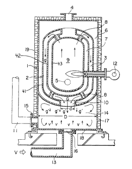
In the embodinuent of the present invention shown in
FIG. 3, the numeral 1 indicates an external drum comprising a
dual wall. An internal drum 2, comprising an external. vessel
41, intermediate vessel 42 and internal vessel 43, is arranged
at a space from and .in the external drum 1. A combustion gas
descending chamber 3 is provided therebet.ween. An outer water
chamber 6 having a hot. water outlet port 4 and a water supply
port 5 in the upper and lower sections thereof respectively is
provided outside the combustion gas descending chamber 3. An
inner water chamber 2? communicating with communicating tubes
5
CA 02092934 2001-03-08
8 in the upper and lower sections thereof to the outer water
chamber 6 is provided inside the combustion gas descending
chamber. A combustion chamber 9 communicating in the upper
section to the combustion gas descending chamber 3 is provided
inside the internal drum 2. An exhaust port 10 is provided
under the combustion gas descending chamber 3. A flue 13 is
communicated to this exhaust. port 10, and a combustor 12 is
detachably mounted through the inner and outer water chambers
6 and 7. In this type of a liquid heating apparatus, 1_ike the
conventional one as described above, a combustion gas flowing
up in the combusticn chamber 9 i.s inverted at the top and
descends through the combustion gas descending chamber 3, an
during this process the combust:Lon gas adequately supplies a
liquid inside the inner and outer water chambers 6 and 7 with
heat. The descending fluidity is improved with the raised
combustion efficiency thereby preventing incomplete combustion
and raising the heat exchange rate between the combustion gas
and the liquid. Thu~~, the temperature of the liquid is rapidly
raised.
In this invention, an external wall of the external drum 1
is extended downward to form a smoke collecting chamber 14
therein with the extended periplneral_ wall 17. Smoke exhaust
ports 15 and 16 are provided in the peripheral wall 17 and the
bottom wall 18 of tre smoke col_Lect=~ng chamber 14, and flues
11 and 13 are detachably mounted on the smoke exhaust ports 15
and 16. It should be noted that the peripheral wall may be
formed as a separated body from the external drum and mounted
to the external drurn 1, and either one of the smoke exhaust
ports 15 and 16 may be omitted. With t:he construction as
described above, a cross-sectiona=L area D of the smoke
collecting chamber 14 is larder than a cross-sectional area of
the exhaust port 10, and results of an experiment show 1=hat the
relation between them should preferably be the one e~,pressed
by the equation of D >_ .~ 1.5 x d. In the liquid heating
6
CA 02092934 2001-03-08
apparatus having the construction as described above, when a
combustion gas flows down at a high f~~ow velocity g through the
combustion gas descending chamber 3 with the flow velocity
increased to the flow velocity G at the exhaust port 30, and
is discharged from t:ne~ exhaust port 10 to t:he smoke collecting
chamber 14, the flow velocity g is reduced to g'; g' i.s lower
than g because a cross-sectional area of said smoke collecting
chamber 14 is larger than that of the exhaust port 10, and the
dynamic pressure, according to the difference, is changed to
a static pressure which maintains a discharge pressure to the
exhaust port 10. If a external disturbance having the flow
velocity of V comes .into the smoke collecting chamber 14 from
the exhaust port of the flue 33, the flow velocity V is reduced
to a flow velocity v which is smaller than V, the external
disturbance being dispersed and weakened. It should be noted
that the numeral 19 in the figure indicates a heat in~~ulating
material which covers the external drum 1.
The present invention is as described above and, according
to the present invention, an internal drum is arranged at a
space from, and inside, an external drum. A combustion gas
descending chamber i.s provided therebetween. An outer water
chamber having a hot water outlet port and a water supply port
in the upper and lower sections thereof is provided outside the
combustion gas descending chamber. An inner water chamber
communicating with communicating tubes in the upper and lower
sections thereof to tr,.e outer water chamber is provided inside
the combustion gas c:iescending chamber. A combustion chamber
communicating to t~~le aforesaid combustion gas de~~cending
chamber in the upper section is provided inside the internal
drum. An exhaust port is provided under the combustion gas
descending chamber. P, smoke collecting chamber having a larger
cross-sectional area than said exhaust port is provided under
the aforesaid exhaust port. A smoke exhaust port is provided
in this smoke c:ollec:ting chamber. The smoke exhaust chamber
may be provided in the side section or at the bottom. of the
7
CA 02092934 2001-03-08
smoke collecting chamber, so that the combustion gas c:an flow
smoothly without generating a large exhaust resistance when the
combustion gas is ~~xhausted. Also, so that an external
disturbance can hard:Ly enter from the exhaust port of the flue
even if cross-sectional areas of the exhaust port and the flue
are not expanded and, accordingly, the external disturbance
does not enter the combustion gas descending chamber nor the
combustion chamber as it is. This prevents energy from being
wasted, the running costs from increasing, and disruption of
combustion in the c:ombustor due to unstable combustion
conditions in the apparatus. Generation of oscillating
combustion and noise is also thereby prevented.
30
8