Note: Descriptions are shown in the official language in which they were submitted.
2~93Q~~
_2_
Backctround of the Invention
1. Field of the Invention
The present invention pertains to the drilling of wells,
such as oil and gas wells and, more particularly, to controlling
the usage of a well drill bit and other aspects of execution of
a well drilling plan. Before a well is drilled, a plan is
developed for at least roughly projecting the timing of such
activities as the replacement of the drill bit, changing the
weight of the drilling mud, setting casing, etc. "Timing" in
this context can literally refer to hours of operation with
reference to the replacement of a drill bit, but can also connote
the depth at which certain actions are taken, especially changes
in mud weight and the setting of casing.
It is rare to follow such a plan precisely. Since a certain
amount of projection, or even guess work, is involved in
developing the plan, the plan must sometimes be modified based
on actual experience while drilling the well. That is to say,
decisions must constantly be made as to whether or not to
continue following the plan, i.e. maintain the plan, or modify
the plan by taking a planned action sooner or later, or at a
greater or lesser depth, than originally planned.
For example, drill bits wear in use, and eventually to such
a degree that it becomes ineffective to continue drilling with
the same bit, and that bit must be replaced. However, replacing
the bit requires a "trip" of the entire drill string, which is
an expensive proposition, particularly if the well has been
drilled to a substantial depth. Therefore, it is highly
desirable to avoid tripping the string prematurely, i.e. when the
209-3-041
-3-
bit still has a good amount of useful life remaining. On the
other hand, it is important to replace the bit promptly when it
has become ineffective.
Unlike the prior art known to Applicants, the present
invention models wear of a given drill bit as a function
primarily of formation abrasiveness, and more specifically, the
abrasiveness of the formation which has actually been drilled by
that bit.
In addition, the present invention provides an improved way
of determining the pore pressure, which can, in itself, be used
to evaluate other aspects of the well drilling plan, e.g. whether
or not to change mud weight and when to set casing.
2093041
-4-
2. Description of the Prior Art
Various means have been devised for attempting to predict
or actively determine bit wear. Some of these have addressed the
determination of wear in the bearings of the drill bit, so that
there remained a need for a means for determining wear of the
outer drilling structure, typically teeth, of the bit.
Some of the most common means currently used to attempt to
predict bit wear simply proceed on the assumption that the
formation which will be drilled in a current well will be similar
l0 to that experienced in a nearby well which has already been
drilled, so that the rate of bit wear will be comparable. No
matter how sophisticated these systems may be, they are not as
accurate as they might be because the lithology in nearby wells
may vary; in other words, the basic hypothesis of such a system
is not always valid.
For example, U.S. Patent No. 4,914,591 to Warren discloses
a system in which a rock compressive strength log for a first
well is generated. While a second such well is being drilled,
another such log is generated and compared with the first. On
the assumption that the formation features of the two wells are
similar, when a significant deviation between the two logs is
observed, it is assumed that the bit is worn or damaged. Thus,
this system assumes that, if the rock compressive strength
"feels" higher, the explanation must be that the bit is worn or
damaged. It does not take into account that the bit may be in
good shape, but rock at the depth in question in the second well
is in fact stronger than rock at the same depth in the first
well. The system does not attempt to determine abrasiveness of
209 304'
-5-
the rock in the second well and model current bit wear thereon.
Other examples are given in a paper by K.L. Mason, titled
"Tricone Bit Selection using Sonic Logs," SPE 13256.
Still other systems have contrived to determine the actual
wear of the drilling structure of a bit currently in use. These
have also had room for improvement.
More particularly, a number of systems have provided means,
literally triggered by physical wear, to somehow change the fluid
flow characteristics of the drilling mud when the bit has become
worn to a certain degree. For example, U. S. Patent No. 3, 058, 532
utilizes a probe or detector which directly detects wear of the
outer surface of a drill bit. When this probe or detector
detects wear beyond a certain limit, a signal, detectable at the
surface, is produced.
In U.S. Patent No. 2,560,328, a blind (closed ended) tube
communicating with the interior of the bit is positioned to be
worn by the rock being drilled along with the bit's cutting
structure. When this tube is worn through, its blind or closed
end is opened, so that drilling mud can pass therethrough, and
the operator will detect a change in the pressure of the drilling
mud.
Similar schemes are described in U. S. Patents No. 2, 580, 860,
No. 4,785,895, No. 4,785,894, No. 4,655,300, No. 3,853,184, and
No. 3,363,702. U.S. Patent No. 2,925,251 is similar except that
the signal produced is electrical, rather than fluidic.
U.S. Patent No. 3,578,092 pertains to a system for
determining wear of a stabilizer blade in which that blade
encapsulates a pocket of crypton which is released when a certain
2 0 -~-, 3 y 4 1
-6-
degree of wear occurs.
The above systems are all susceptible to inaccuracies and/or
mechanical failures.
U.S. Patent No. 4,030,558 involves magnetically recovering
and analyzing bit fragments which are carried back to the surface
in the drilling mud. The analysis involves observation under a
microscope. It is therefore tedious, time consuming and requires
a fair degree of specialization by the analyst.
U.S. Patent No. 3,345,867 does attempt to extrapolate bit
wear from ongoing drilling conditions. In particular, the ratio
between the bit rotational speed and the cone rotational speed,
in a roller cone type bit, is calculated. The system relies on
the idea that variations in that ratio give an indication of the
wear of the teeth on the outside of the cones. The cone
~15 rotational speed is determined by observing the frequency
response of the vertical accelerations in the drill string. This
system is too simplistic and may not be as accurate as is
possible. It does not attempt to analyze the lithologies
actually being drilled nor to determine bit wear as a function
of abrasion by the formation which has been drilled.
Other systems which attempt to utilize real-time parameters
but which, again, are too simplistic and fail to take actual
formation characteristics into account, are disclosed .in U.S.
Patent No. Re. 28,436 and U.S. Patent No. 4,773,263.
U.S. Patent No. 4,926,686 to Fay discloses a system for
determining bit wear dynamically, i.e. while the bit is drilling.
The basis for this is variation in a curve obtained by plotting
torque as it varies with weight on bit, i.e. the effect the wear
2093041
_7-
has on the operation of the apparatus. Data about the formation
appears to be derived prior to drilling the well in question.
There is no dynamic determination of a wear-affecting variable
of the formation, such as abrasiveness. Rather, wear is modelled
'S as a function of drilling parameters affected by wear.
A similar approach is taken in a paper by T.M. Burgess and
W.G. Lesso, titled "Measuring Wear of Milled Tooth Bits Using MWD
Torque and WOB," SPE/IADC 13475.
Similarly, U.S. Patents No. 2,669,871, No. 3,774,445, and
No. 3, 761, 701 all attempt to model bit wear as a function of
various drilling values, such as weight-on-bit, rate of
penetration, revolutions per minute, and time. However, these
models fail to take into account the abrasiveness of the
lithology being drilled, which is a highly significant factor,
particularly when attempting to model wear of the exterior, i.e.
teeth, of a bit. The same is true of the method disclosed in
U.S. Patent No. 4,685,329, which considers torque-on-bit, weight-
on-bit, rate of penetration and revolutions per minute.
U.S. Paterit No. 2,096,995 discloses a system which does
attempt to project certain information about the lithology being
drilled. However, this information is not used to attempt to
determine or model bit wear, and, on the contrary, the patent
treats bit wear as only a relatively minor factor which might be
taken into account in connection with the basic lithology
determination.
U.S. Patent No. 4,064,749 teaches a system directed at
determining formation porosity from drilling response. The
patent does mention a determination of "tooth dullness." The
209304'
_8_
operational input for this determination is quite different from
that of the present invention, and it would appear that the
determination lacks adequate precision, as it will only determine
dulling in excess of a bit grade No. 5.
U.S. Patent No. 4,794,535 involves an attempt to determine
when a bit should be changed using a mathematical model.
However, this model, which is based on bit economics, simply uses
the formation abrasion calculated from the previous bit run; it
does not attempt to model bit wear based on the lithology
actually drilled by the bit in question. Nor does this method
include as much input as to the bit geometry as does the present
invention, and to that extent, the results are less precise.
U.S. Patent No. 3,898,880 is even less sophisticated. In
essence, wear is predicated simply as a function of time, with
no adjustment for the liahology being drilled, nor for the actual
bit geometry:
U.S. Patent No. 4,627,276 probably comes closer to any of
the above to effectively utilizing lithology actually drilled in
a given bit run in some type of wear determination. However, the
system only "kicks in" to produce such a determination when the
bit is drilling in shale. At that time, the bit may have already
been significantly worn by having drilled through sandstone. By
way of contrast, the present invention continually interprets the
nature of the lithology currently being drilled, and continually
determines current bit wear, taking into account all the
lithology which has been drilled up to that point.
A paper entitled "Use of Single-Cutter Data in the Analysis
of PDC Bit Designs: Part II/Development and Use of the PDC Wear
209 3041
_g_
COMPUTER CODE" by D.A. Glowka and published in the August 1989
issue of JPT (Journal of Petroleum Technoloay), describes a
technique for predicting wear of the cutters of PDC type drag
bits using formation abrasion and sliding distance of a tooth as
primary factors. However, the system was developed through
laboratory experiments where the lithologies were known, and the
article does not teach any means for analyzing lithology drilled
in real-time. Among other differences, this system also utilizes
additional parameters which, while feasible in laboratory
analysis, would be very difficult to implement in real-time, e.g.
the depth of cut of each tooth or cutter.
Considered cumulatively, the prior art shows that
determinations of bit wear are a significant problem, to which
much attention has been given, but apparently without any really
1~5 definitive solution. More specifically, it appears that the
known methods generally suffer from an inability to accurately
determine bit wear on the basis of the nature, and more
specifically abrasiveness, of the lithology actually drilled by
a given bit.
Turning to the pore pressure aspect, U.S. Patent No.
4,981,037 to Holbrook et al and a related SPE paper No. 1666,
"Petrophysical-Mechanical Math Model for Real-time Wellsite Pore
Pressure/Fracture Gradient Prediction" describe a way of
determining pore pressure on the basis of lithology actually
drilled in the well in question. However, this prior system
views pore pressure as a function of absolute rock properties.
Furthermore, it is limited to a determination of the pore
pressure at a site a significant distance above the then current
-l0- 209304't
location of the bit, e.g. seven to fifty feet.
Summary of the Invention
Embodiments of the present invention encompass methods,
hardware and software for controlling drill bit usage and/or
other aspects of a well drilling plan. The wear of the cutting
structure, i.e. teeth, of a drill bit is mathematically modeled
on a continual basis utilizing real-time data which take into
account the abrasiveness of the very lithology which has been
drilled by the bit under consideration. Since that lithology is
so important in the degree of wear, at least of the exterior
cutting structure of the bit, the present method is believed to
produce much more accurate results, and should drastically reduce
the extent to which drill bits are changed either prematurely or
too late.
In accordance with one aspect of the invention there is
provided a method of controlling drill bit usage, comprising the
steps of : drilling at least a portion of a given oil or gas
exploration or production well with a given drill bit;
continually measuring drilling data from the well and producing
outputs indicative of the drilling data; converting the outputs
indicative of the drilling data into electrical drilling data
signals and inputting the electrical drilling data signals to a
computer; continually processing the drilling data signals to
produce a variable signal indicative of an abrasive-wear-
affecting variable for the lithology which has been most recently
drilled with said bit; continually processing the variable signal
to calculate current abrasive wear of the bit by the total
_ _ __ ... ._ . .._ _ ~.~. ...
__.__. ._
-l0a- E 2 0 9 3 0 4 1
lithology which has been so drilled thereby and produce a wear
calculation signal; and continuing use of the bit or retiring the
bit in accord with said wear calculation signal.
In accordance with another aspect of the invention there is
provided a method of controlling drill bit usage comprising the
steps of: drilling at least a portion of a given oil or gas
exploration or production well with a given drill bit;
continually measuring drilling data from the well and producing
outputs indicative of the drilling data; converting the outputs
indicative of the drilling data into electrical drilling data
signals and inputting the electrical drilling data signals to a
computer; continually processing the drilling data signals to
produce at least one signal indicative of the lithology which has
been most recently drilled with said bit; continually applying
said signal indicative of said recently drilled lithology to
adjust a wear coefficient signal; continually processing the wear
coefficient signal to calculate current abrasive wear of the bit
and produce a wear calculation signal; and continuing use of the
bit or retiring the bit in accord with said wear calculation
signal.
In accordance with yet another aspect of the invention there
is provided a data processing system comprising: memory means
for storing a set of bit data signals, including signals
indicative of parameters of a drill bit, and a set of drilling
data signals, including signals indicative of parameters of an
oil or gas exploration or production well drilling operation
being performed with said bit; means for processing said data
signals to produce a variable signal indicative of an abrasive-
~,,,r
r'::
.;
j 2093041
-lOb-
wear-affecting variable; means for processing said variable
signal to calculate abrasive wear of said bit as a function of
said variable signal and produce a wear calculation signal; and
an output device for providing a visual indication of said wear
calculation signal.
In accordance with yet another aspect of the invention there
is provided a method of controlling the execution of a well
drilling plan, comprising the steps of: drilling at least a
portion of a given oil or gas exploration or production well with
a given drill bit; continually measuring drilling data from the
well and producing outputs indicative of the drilling data;
converting the outputs indicative of the drilling data into
electrical drilling data signals and inputting the electrical
drilling data signals to a computer; continually processing the
drilling data signals to produce a drilling strength signal
indicative of the drilling strength of the lithology which has
been drilled by said bit, relative to said bit, and closely
adjacent said bit; continually processing the drilling strength
signal to calculate pore pressure as a function of said drilling
strength; and continuing or modifying said well drilling plan as
a function of said pore pressure calculation.
In accordance with yet another aspect of the invention there
is provided a data processing system comprising: memory means
for storing a set of bit data signals, including signals
indicative of parameters of a drill bit, and a set of drilling
data signals, including signals indicative of parameters of an
oil or gas exploration or production well drilling operation
being performed with said bit; means for processing said data
2093041
-10c-
signals to produce a drilling strength signal indicative of the
drilling strength of the lithology drilled by said bit, relative
to said bit, and closely adjacent said bit; means for processing
said drilling strength signal to produce a pore pressure signal
indicative of pore pressure.
More specifically, at least a portion of a given well is
drilled with a given drill bit. An abrasive-wear-affecting
variable for the lithology which has been most recently drilled
is continually evaluated. Based on that variable, abrasive wear
of the bit by the total lithology which has been so drilled
thereby is continually calculated. The continued use, or
conversely, retirement, of the bit is controlled in accord with
that wear calculation.
The aforementioned abrasive-wear-affecting variable is
preferably drilling strength of the formation. Wear is
calculated as a function of at least that drilling strength and
the linear distance traversed by a point on the drill bit.
Preferably, the wear is calculated as a function also of a wear
_2093041
coefficient which is adjusted for the recently drilled lithology
as well as for the nature of the drilling mud being used.
The depth of the well is continually, i.e. at least
periodically if not continuously, measured. The aforementioned
drilling strength is re-evaluated each time the bit increases the
depth of the well by a given increment, e.g. one foot. Each
drilling strength value so obtained is compared with at least one
drilling strength reference and classified as one of at least two
given categories of lithology, e.g. sandstone or shale.
Respective arrays of drilling strength values are maintained for
each such category of lithology. Each drilling strength value,
as it is so classified, is entered into the respective array, and
the oldest value in that array is simultaneously removed. The
values in each respective array are averaged, and the relative
volumes of the respective categories of lithology are determined.
Wear is calculated as a function of drilling strength by
calculating it as a function of those relative volumes, which in
turn are functions of the drilling strength.
The drilling strength of the rock, as "felt" by the bit, is
a function not only of the nature of the rock itself, but also
of the pressure differential across the interface between the
wellbore and the formation being drilled. Therefore, to give a
more accurate model of the drilling strength, and thus a more
accurate determination of its effect on the bit, each drilling
strength value obtained in the manner described above is
preferably adjusted for that pressure differential, in the
current lithology, before it is compared and classified according
to lithology.
i 2093041
-12-
One of the above-mentioned arrays, preferably the array for
shale, has its average used to compute pore pressure, which is
thus determined as a value relative to the drill bit and its
action, and at a location immediately adj acent the bit . The pore
pressure can be used to. periodically update the differential
pressure which, as mentioned above, is used to adjust drilling
strength for greater accuracy in calculating the wear of the bit.
In addition, the pore pressure can be used, independently of any
bit wear calculation, to evaluate other aspects of the well
drilling plan, whereafter such aspect is either maintained or
modified. For example, based on such an evaluation of pore
pressure, the point at which mud weight is changed and/or the
point at which casing is set may be changed from that originally
prescribed by the plan.
The data used to perform various of the steps described
above include, in part, bit data taken from the conf iguration and
nature of the bit and its cutting teeth. As previously
mentioned, these data are periodically updated to account for the
wear modeled in the method itself. One such item of bit data is
at least one current tooth flat parameter such as width or area.
At the beginning of a run, this flat parameter is measured or
taken from manufacturers' specs. However, since it is this
parameter which increases due to wear, the system of the present
invention continually calculates a current value for that tooth
flat parameter, and that updated parameter, while a final or near
final result of the calculations in question, is also part of the
new data which will be used in the next calculation by virtue of
such updating. The other data represent current drilling
2093041
-13-
conditions. Some are known, and others can be obtained by
existing technology such as measurement-while-drilling or "MWD"
techniques available in the art. The only aspect which must be
entirely empirically determined from previous bit runs is a
strength concentration factor, which also goes into the
calculation of drilling strength described above.
In another aspect, embodiments of the present invention
encompass methods, hardware and software for controlling drill
bit usage in which at least a portion of the well is drilled with
a given bit, the lithology which has been most recently drilled
is continually evaluated, and a wear coefficient is continually
adjusted for that recently drilled lithology. The current
abrasive wear of the bit is continually calculated based on the
wear coefficient, and the continued use or retirement of the bit
is controlled in accord with that wear calculation. Preferably,
the adjustment of the wear coefficient is done so as to produce
wear calculations increasing in magnitude as the proportion of
sandstone relative to shale, in the lithology so drilled,
increases.
Various objects, features and advantages of the present
invention will be made apparent by the following detailed
description, the drawings and the claims.
.~ f 209041
-14-
Brief Description of the Drawings
Fig. 1 is a flow diagram illustrating the overall method
according to the present invention.
Fig. 2 is a detailed flow diagram illustrating the functions
performed by the computer 22.
Fig. 3 is a flow diagram of the subsystem represented by
block 80 in Fig. 2.
Fig. 4 is a longitudinal cross-sectional view of a roller
cone drill bit of a type to which the present invention can be
applied, showing one of the roller cones in elevation, and
illustrating where various input bit data are taken.
Fig. 5 is an enlarged detailed front view of one of the
teeth of the bit shown in Fig. 4 illustrating where other bit
data are taken.
Fig. 6 is a side view of the tooth of Fig. 5 showing where
still other bit data are taken.
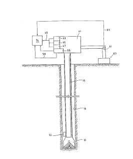
Fig. 7 is a diagrammatic view of the well illustrating means
for determining current or real time drilling data.
2093041
-15-
Detailed Description
Referring first to Fig. 1, there is described a method for
controlling the usage of a roller cone type drill bit 10 as well
as other aspects of the execution of a well drilling plan. Prior
to the commencement of usage of the bit 10, certain measurements
and other information, which make up the initial bit data, are
taken from the bit 10 as indicated by the step box 12. These
data are entered into a computer 22 as indicated by the arrow 20.
The bit 10 is run into a well 16 on drill string 15 and
commences drilling in that well as indicated by the step box 18.
As indicated by the step box 24 and arrow 26, certain
constant and real-time drilling values are obtained from the
drilling operation 18 using well known techniques as needed.
These values make up the drilling data which are entered into
computer 22 as indicated by arrow 28.
In a manner to be described more fully below, the computer
22, which is programmed with special software forming a part of
the present invention, calculates current abrasive wear of the
cutting structure of bit 10 on an ongoing or continual basis.
As indicated by arrow 30, the computer is connected to an output
device 32 which provides a perceptible indication of the current
wear. Thus, the output as to wear is indicated by the device 32.
In Fig. 1, device 32 is diagrammatically indicated as a visible
scale having a movable indicator 34 which can track between a
zero point at the left end of the scale to a limit at the right
end. An operator controls continued usage or retirement of the
bit 10 in accord with the current reading of device 32 as
indicated by arrow 36.
2093041
-16-
Specifically, as long as the indicator 34 is located below
the right hand limit point, the operator will allow continued
usage of the bit in the well 16, However, when the indicator 34
reaches the right hand limit, the operator will instruct that the
bit be removed from the well 16 and retired, as indicated by
arrow 38. ("Retirement" as used herein does not preclude re-
dressing for later use.)
It should be understood that the device 32 as illustrated
is only a diagrammatic and representative device, and that
various other types of output devices may be used either alone,
or in conjunction with one another. For example, the output
device might be a plotter or printer and might be used in
conjunction with another device which will produce an audible
signal or alarm when the limit is reached. Even a visual scale
type device, as illustrated, could be modified in many ways. For
example, it may not indicate a specific limit, but rather the
operator could simply watch for a certain numerical value,
identified in advance, as the limit for a given bit.
As will be explained more fully below, a by product of the
preferred software for determining bit wear is pore pressure.
This can be transmitted from the computer 22 to another suitable
output device 42 as indicated by line 40. Then, as indicated by
line 44, this pore pressure can be used to control other. aspects
of the execution of the well drilling plan, e.g. whether or not,
and when to change mud weight, how much to change the mud weight,
and when to set casing. Given a pore pressure value, it is well
known in the art how to relate this to mud weight and casing
plan. For example, an increase in pore pressure generally
2093041
-17-
indicates a need for an increase in mud weight.
Referring now to Figs. 4-6, the various bit data determined
as indicated at step box 12, will be described. Fig. 4 is a
simplified representation of a typical roller cone type drill
bit. In the exemplary embodiment of the method of the present
invention to be described, the software and calculation methods
are tailored for roller cone type bits. However, it is believed
that, using similar general principles, the method and software
could be modified to calculate wear of other types of bits, such
as drag bits, so long as the bits in question do undergo
substantial external abrasive wear by the formation. Roller bit
10 is shown in the well bore 16 so as to better illustrate its
operation and drilling environment. It will be understood that
the measurements taken at step 12 are taken before the bit is put
into the borehole and commences drilling.
Bit 10 includes an uppermost threaded pin 46 whereby the bit
is attached to the drill string 15. A central flowway 48 opens
in through the upper end of pin 46 and branches out through the
crown 47 of the bit body, there communicating with several
nozzles, one of which is diagrammatically shown at 50. In use,
drilling mud is pumped through passageway 48 and nozzle 50 to
cool the cutting structures and carry the cuttings back up
through the annulus 52 of the well 16.
Below its crown portion, the bit body branches into several
legs. A typical bit includes three such legs, and two of the
three are shown at 54 in Fig. 4. Each leg 54 rotatably mounts
a roller cone 56 having exterior cutting structures in the form
of teeth 58. Bearings 60 are provided between the cones 56 and
2093041
-18-
their respective legs 54 to facilitate rotation.
The bit values measured at step 12 and forming the bit data
subset of the input data for the computer 22 include the overall
diameter Db of the bit taken at its widest part, the inner
diameter Dn of the nozzle 50, the number of nozzles, Nn, and the
number of teeth, Nt.
Each bit has a profile surface 61 which can be generated by
connecting the outer surfaces of the lowermost teeth 58 on the
cones 56. In use, this profile generally coincides with the
profile 61 of the earth formation as it is drilled by the bit 10.
Another of the bit data used in the present invention is the
distance Hb from the outermost end of the nozzle 50 to the
outermost point of the profile surface 61, measured perpendicular
to the centerline of the bit. It should be understood that, in
some bits, the nozzles project outwardly from the bit body more
than in the embodiment illustrated, so that this distance Hb is
not necessarily the same as the distance from the underside of
the crown 47 of the bit body to the profile surface 61.
It can be seen that various of the teeth 58 on each cone 56
are of different sizes and are located at different positions
along the longitudinal extent of the cone 56. In general, those
teeth closest to the base of the cone are largest, while those
closest to its tip are smallest. Certain of the bit data are
taken from measurements of these teeth. In the embodiment being
described herein, an exemplary bit tooth 58a is chosen for
calculation purposes, and is assumed to represent an average size
and position. To enhance the accuracy of such an extrapolation,
the exemplary tooth 58a is selected at a point approximately
2pg3041
-19-
midway between the relatively large tooth adjacent the base of
the cone and the relatively small tooth near the tip of the cone.
In the exemplary bit illustrated, the teeth 58 are of the
milled type, which are formed integrally with their cones 56.
They may or may not be hard faced. Other types of teeth, such
as teeth which are separately formed and inset into their cones,
are also employed in roller cone bits. Wear of any of these
tooth types can be calculated in accord with the present
invention, but different input data are needed for each type.
Thus, another factor which may be considered part of the bit
"measurements" for present purposes is the factor Bt which
reflects the type of bit, i.e. either milled tooth or insert
type.
In preferred embodiments, the bit values also include
parameters based on the materials) of which the teeth are
formed. If the tooth has hard facing, these values will include
the hardness, Gf, and thickness, Hf, of the hard facing layer,
and in any event, these values will include the hardness, Gt, of
the basic material of the main body of the tooth.
The exemplary milled tooth 58a used for averaging purposes
in the exemplary embodiment includes leading and trailing
surfaces 64 and 66 (with reference to the direction of movement
of the tooth in use), and side surfaces 68. The leading and
trailing surfaces 64 and 66 are disposed at an angle a while the
side surfaces are disposed at an angle (i. In the embodiment
shown, a is part of the bit data.
The tooth 58a also has a tooth flat 70 at its outer end,
which is the portion of the tooth which contacts the earth
3 2093041
-20-
formation. Among the initial measurements taken at step 24 are
the initial tooth flat length, Lt, being the length of the flat
70 measured between sides 68, and the initial tooth flat width,
Wti, being the extent of the flat 70 parallel to the direction of
travel, i.e. between leading and trailing surfaces 64 and 66.
Another item of bit data is the current tooth flat width,
Wtc. At the beginning of a bit run, Wtc - Wti~ Wtc is
periodically updated on the basis of wear calculations made in
accord with the invention, as explained below. However, because
~i is so small, tooth flat length, Lt, will change little through
an acceptable amount of wear. Therefore, in this embodiment, Lt
is assumed constant, and ~ is not part of the bit data, although
they might be used in other embodiments, as will be apparent to
those of skill in the art.
The initial tooth height, Ht, measured from the base of the
tooth (where it meets its cone) to its flat 70, is another one
of the bit data. The bit data also include two other values,
which can be calculated from bit measurements or taken from
manufacturers ~' specs . These are the volumetric rate of mud f low
through the bit nozzle 50, vm, and the velocity of mud flow
through the bit nozzle, Sm. The bit data also include a pair of
wear coefficients, Ceha and Cea, for shale and sandstone,
respectively, and which vary depending on the type of tooth, i . a .
milled steel (as shown), tungsten carbide faced steel, or
tungsten carbide insert. For a milled steel tooth, as shown,
Cgha = 12 x 10-6 and Cea = 192 x 10-6.
209 3041
-21-
To summarize, the bit data for a preferred embodiment, along
with their units of measurement, include:
bit diameter, Db, in.
ID of nozzle, Dn, 1/32 in.
distance of nozzle from profile, Hb, in.
bit type factor, Bt, no units
hardness of tooth, Gt, kg./mm2
first included angle, a, degrees
second included angle, ~3, degrees
initial tooth flat width, Wti~ in.
current tooth flat width, Wt~, in.
shale wear coefficient, Ceha, no units
sandstone wear coefficient, Csa, no units
tooth flat length, Lt, in.
tooth height, Ht, in.
volumetric rate of mud flow through nozzle, Vm,
gal./min.
velocity of mud flow through nozzle, Sm, cm./sec.
number of nozzles, Nn, no units
number of teeth, Nt, no units
Sm is included in the start-up data for convenience,
although it will be appreciated that Sm could be calculated by
the computer from Dn and Vm.
In addition, if the teeth are hard faced, the data will
include:
thickness of facing, Hf, in.
hardness of facing, Gf, kg./mm.2
The second subset of input data, i.e. the drilling data, are
either known at the outset and remain constant or are taken from
real-time drilling values measured at step 24. These include:
20 9 3041
-22-
mud weight, Mm, lb./gal.
mud viscosity, T, poise
weight-on-bit, Mb, lb.
speed of bit, Sr, rpm
rate of penetration of bit, Sb, ft./hr.
height of kelly bushing, Hk, ft.
water depth (for offshore wells), Hw, ft.
measured depth of well, Wm, ft.
true vertical depth of well, W~, ft.
With the exception of a few empirically determined
constants, which will be pointed out below, all constants for
which actual numerical values are given in the equations and
other relationships below are conversion factors. If the above
listed units of measurement are used for the data, these
conversion factors eventually cancel out of the equations and
become superfluous. The same would be true if another, e.g.
metric, scheme of consistent units were used. However, if the
units of only certain data are changed, different, and necessary,
conversion factors will be needed, as will be apparent to those
of skill in the art.
The mud type, i.e. fresh water, salt water or oil-based,
should also be taken into account. The equations below are for
a fresh water base, and some adjustments would be made in the
constants for oil-based muds. Specifically, since the lubricity
of an oil-based mud is about twice that of a fresh water-based
mud, and the wear coefficient, Ct, discussed below, is inversely
proportional to lubricity, it would be appropriate to divide Ct
by 2 to adjust for use of an oil-based mud. Similar adjustments
might be made for salt water-based muds.
209304'
-23-
Referring now to Fig. 7, determination of those drilling
values which vary while drilling is diagrammatically illustrated.
Fig. 7 may thus be considered a more detailed rendition of step
box 24 in Fig. 1.
Equipment such as the kelly, rotary table, etc., located on
the drilling platform is cumulatively and diagrammatically
indicated at 41. Measured depth of well, Wm, rotary speed of
bit, Sr, and rate of penetration, Sb, can be measured or
otherwise determined by conventional instruments, well-known in
the art, located on or about equipment 41. Such instruments, for
measuring Wm, Sr and Sb, respectively, are diagrammatically
represented by black boxes 43, 45 and 47. Their outputs can be
converted, by well known means, into electrical signals fed into
memory 74 of computer 22 by lines 49, or they may have visual
outputs which are fed into computer 22 by an operator.
The measurement of weight on bit, Mb, can utilize a signal
from a well-known downhole instrument, such as strain gauge 51.
The output from this instrument may be conveyed to the surface
by well known means, such as mud pulse telemetry. The signal is
received by a receiver apparatus 55, which converts it to an
electrical signal which can be fed to memory 74 by line 59 or
manually. Alternatively, Mb can be determined from hook loads
measured by a strain gauge adjacent the draw works, i.e.,as the
difference in the hook loads before and after the bit is placed
on the bottom of the hole.
If mud weight, Mm, or viscosity, T, change during operation,
this can be determined by conventional instrumentation 61 in the
mud circulation system 63 to produce electrical outputs
communicated to memory 74 by line 65. Alternatively, the
'iO nner~t~r ~~n inp»t- the nh~nc~e(s) m~nn~llv.
2093041
w
-24-
True vertical depth, W~, is determined from periodic surveys
taken, by well-known means, intermittently with episodes of
drilling. If desired, W~ can be roughly adjusted between surveys
by extrapolating from corresponding changes in Wm.
Referring now to Fig. 2, the operations of the computer 22
will be generally described. As previously mentioned, there are
two subsets of input data, the bit data 72 constituting and/or
extrapolated from the bit measurements taken at 12, and the
drilling data 74, from the known and real-time drilling values
determined at 24. Boxes 72 and 74 may also be considered to
represent memories containing these data. Other boxes in Figs.
2 and 3 are called "step boxes" herein. They represent steps in
the method as well as means, in computer 22, for performing those
respective steps. As indicated by arrows 76 and 78, at least
some of the parameters in these two subsets of data are
communicated to a subsystem 80 wherein the drilling strength of
the lithology currently being drilled is computed. This
subsystem is shown in greater detail in Fig. 3 and will now be
described with~reference to Fig. 3.
Certain of the bit data 72 and drilling data 74 are used to
solve for an intermediate parameter designated Z1, as indicated
at 82. The computer 22, and specifically its subsystem 80, is
programmed with appropriate software to solve for Z1 in accord
with the following functional relationships and definitions:
2093041
-25-
The variable Z1 is a dimensionless stress-strain
relationship defined by the equation:
(1) Z1 = (0.008466Sb)(hydraulic impact energy) ~ where
di
(2) dl = (Reynold's number)(mud density)(bit characteristic
number)(Sr)(hydraulic impact velocity)3.
The factors of dl are, in turn, defined by the following
relationships:
(3) Reynolds number = (mud density)(Sm)(bit characteristic
number)
T
where mud density = Mm
8.34 ,
and bit characteristic number = 2.54 (DbHtWti~l/3 .
Substituting the definitions of mud density and bit
characteristic number into equation (3), we get a formula for
Reynolds number. Substituting the resulting definition of
Reynolds number into equation (2), and also substituting the
definitions of mud density and bit characteristic number into
equation (2), we get a formula for dl. Substituting this
definition of dl into equation (1), we get Z1 expressed in terms
of the above basic input data and two intermediate terms,
hydraulic impact energy (total) and hydraulic impact velocity.
In defining the latter two intermediate terms, we utilize
two other intermediate terms, Sf and Se. Sf is the mud flow
velocity at the profile surface 61 (Fig. 4), and Se is an
adjusted mud flow velocity. It is known that Sf can
be defined in terms of basic input data as:
MRR 3l '93 14:14 HERB HOU. PRGE.04
j _ ~ n
--209 301
-26-
St = 63.09 Vm = 63.09 V@
E nozzle areas E n (Dn/2)Z
We also utilize intermediate terms E, or energy, and H, or ii
hydraulic impact energy par nozzle, defined as:
H = (mud density)(Sf)3(n)(2.84 D~)Z/8
~j (S~) 3 (r) (2. 54 D~) 2
8.34 8
8aaed on empirical findings, we have defined a limit R, in
terms of basic input data, to adjust for certain bit designs in
which the nozzles extend away from the crown of the bit: R a
H~/Dn. It has been empirically determined that,
if R>6, then
Se = 6.2 Sf
;s
R
;:
and E = 4.1 H
~ R
and if R<_6, then
S~ ~ Sf~
and E = H(1-0.08968 + 0.005882).
;;
Since Sf and R are defined in terms of basic input data, H
and So are defined in tex~nas of S~ and R, and E is defined in
terms of H and R, Se and E are ultimately determinable from the
input data. Note that the constants in the above definitions of i.
St and E are necessary empirical constants, not conversion
i
factors.
20930~'~~
-27-
We then define:
hydraulic impact energy - EE for all nozzles, and
hydraulic impact velocity - ESe
Nn
Accordingly, reverting to the mathematical definition of Zl,
and substituting for hydraulic impact energy and hydraulic impact
velocity, Z1 can be defined completely in terms of the input
data. There are two possible equations for Z1, depending on
whether R>6 or R56. The software for step 82 (Fig. 3) may be
operative to compute R from input data, compare R to 6, and then
use one or the other of these two equations to solve for Zl in
terms of input data. R will remain constant for a given bit, and
so will the ultimate equation for Z1.
Referring again to Fig. 3, Z1 is transmitted to the next
step 84 of the software, where Z1 is used to solve for another
dimensionless stress-strain relationship term Z2, by the
following equation:
(4)Log.(Z2) - 28.26939 + 6.097267 Log(Z1) + 0.302986 [Log(Zl)~2.
All constants in equation (4) are necessary empirical
constants, not conversion factors.
While steps 82 and 84 have been described as separate steps
to facilitate understanding, it should be understood that they
can be combined in the software. Specifically, in equation (4),
each occurrence of Z1 can be replaced by its formula for R>6, -
expressed in input data and derived as explained above. The same
is repeated using the Z1 formula for R<6. This results in two
equations for Z2, in terms of the input data, one for R>6 and one
for R<6. The computer can then be programmed to go directly from
computation of R and comparison of R with 6 to computation of Z2,
lJSlnq the anproPri~te one of smh twn fnrmol~s.
2093041
-28-
Z2 is also functionally related to drilling strength in
terms of input data. Transmitting Z2 and the data by which it
is related to drilling strength to step 86, this relationship is
. used to solve for drilling strength. The relationship is
developed below. To the extent that certain terms have already
been defined in developing Z1, their definitions will not be
repeated.
(5) Z2 = 4.448 x 10⁵ Mb (mechanical stress + hydraulic stress)
d2
Mechanical stress _ 4.448 x 10⁵ Mb
Ak Nk
Ak = 2.542WtcDb
Nk = number of teeth in contact with formation
_ BtNt.
(It has been empirically determined that Bt - 0.15 for milled
tooth roller cone bits, and Bt = 0.11 for insert tooth roller
cone bits.) Thus, mechanical stress can be expressed in terms
of basic input data.
Hydraulic stress (mud density)(E area of nozzles)2
(hydraulic impact velocity)
Ak
where area of nozzle - ~r(2.54Dn/2)2.
CA 02093041 2000-04-12
- 29 -
Thus, recalling that hydraulic impact velocity can be expressed
in terms of basic input data, and Se can be determined from basic
input data, hydraulic stress can be expressed in terms of basic
input data.
Also,
(6) d2 - (drilling strength)2.
Substituting from the above into equation (5), we can derive an
equation for Zz in terms of basic input data and drilling
strength.
Solving equation (4) for Z2, and substituting that solution
for ZZ into the last.-mentioned equation for Z2, we can then solve
for drilling strength, the only remaining unknown.
It should be n~~ted that such solution for drilling strength
will involve the term Se, which as explained above has two
different definitions, depending upon whether R>6 or R<6. As one
of skill in the art wall appreciate, the software can be
developed in any one of a number of equivalent ways, to take this
into account. For example, the calculation and comparison of R
which precedes the solution for Z1 at step 82 can be used again
at step 86 to select one of two different formulas for drilling
strength developed from the two respective definitions of Se.
Alternatively, the comparison of R with 6 can be made again at
step 86.
However, this probably becomes moot for the following
reason: Just as steps 82 and 84 were described separately to
facilitate understanding, but could be combined into one step as
explained above, that one step could likewise be combined with
step 86. That is, it i.s possible to develop two equations for
drilling strength, one for R>6 and one for R<6, with each of
those two equations expressed entirely in terms of the input
-.
2 0_,9 ~ _,~_~4 '~
-30-
data. Indeed, the computation of drilling strength is indicated
as a single step at 80 in Fig. 2. Step 80 may consist of an
initial evaluation and comparison of R to select one of two
equations for drilling strength which may then be used throughout
the process as long as the same drill bit is being employed.
Alternatively, step 80 may contain substeps, as shown in Fig. 3
and described above.
For simplification of the flowcharts of Figs. 2 and 3, an
arrow from a memory 72 or 74 means that at least some, but not
necessarily all, of the data in that memory are used in the step
box to which the arrow is directed. Also, in some instances.
data from the memory are also used in a subsequent step in a
chain of step boxes, and that data is not necessarily used at
each preceding step in the chain; arrows directly from the
memory to the subsequent step box may be omitted to avoid
confusing the chart with too many lines. Again, the same may be
true of output from one step box connected to other step boxes
in a chain. Thus, the chart should be read with this
specification.
The drilling strength obtained at step 80 is next adjusted
for differential pressure effects at step 88. This is done using
the relationship:
adjusted drilling strength = (drilling strength) (e-M dp)
where M = 0.001 (an empirically determined constant) and
dp = the pressure differential across the wall of the well, i.e.
between the pressure of the mud in the well and the pressure in
the formation just outside the well.
2093041
-31-
dP - 0.05188 [Mm W~ - q (W~ -
where q - pore pressure.
Pore pressure, q, can be determined by conventional means or by
a sub-routine indicated at 120 and described below.
The adjusted drilling strength obtained at step 88 is then
transmitted to step 90 where it is compared with at least one
drilling strength reference so that the corresponding lithology
can be classified as to type. For the vast majority of
formations, it is sufficient to classify each value obtained as
either sandstone (abbreviated "sand" or "sa." herein) or shale
("sha. ") . As indicated by arrows 92 and 94, this comparison, and
more specifically the drilling strength references, utilize the
current shale and sand baselines developed at steps 106 and 108
as described below.
If
('1) sha. baseline - 3(sha. std. dev.) < drilling strength
< sha. baseline + 3(sha. std, dev.),
then the lithology which yielded that drilling strength is
classified as a shale.
If
(8) sa. baseline - 3(sa. std. dev.) < drilling strength <
sa. baseline + 3(sa. std: dev.),
then the lithology corresponding to that drilling strength is
classified as a sand.
Each drilling strength, so classified, is then paired with
the respective true vertical depth, W~, for which it was
obtained, since drilling strength increases with depth. W~ is
supplied to step 90 from the drilling data 74 as indicated by
~,r~~,
2 0 9 3 0 4 '~'
_ -32-
If the drilling strength has been classified as a shale,
that drilling strength, as paired with the corresponding true
vertical depth, W~, is placed in an array 98 of fifty such
drilling strength\true vertical depth pairs, as indicated by
arrow 102. When the most recent such pair, Win\shale drilling
strengths, is placed into the array, the oldest such pair,
Wvs-so\shale drilling strengths_5o, is deleted, as indicated by
the hatch lines through the lower end of the array 98. Thus, an
array of the fifty most current such pairs of values for shale
is maintained in the array 98.
Similarly, if a drilling strength is classified as a sand,
it, paired with its respective true vertical depth, is placed in
a sand array 100 as the most recent pair, Was\shale drilling
strengths, as indicated by arrow 104, and the oldest such pair,
W"n-5o\sand drilling strengths_5o, is deleted.
Each time a new pair of values comes into the array 98, a
new shale baseline or mean for the fifty current shale drilling
strengths is computed as indicated at 106. A sand baseline or
mean is similarly maintained on a current or updated basis as
indicated at 108. As already mentioned, these current baselines
are transmitted to the comparison and classification step 90 as
indicated by arrows 92 and 94.
It will be appreciated that, upon start up of a bit run, a
shale baseline and sand baseline will be needed for the
comparison step at 90 until the arrays 98 and 100 fill up. For
this start up purpose, we use the shale baseline from the last
bit run and define:
CA 02093041 2000-04-12
- 33 -
sa. baseline - (sha. baseline + sha. std. dev.)
2
The shale and sand baselines obtained at steps 106 and 108
are transmitted to step 1.10 where the relative volumes of shale
and sand are computed. This computation also utilizes the current
adjusted drilling strength value, obtained at 88 and transmitted
to 90, as indi.catecl by arrow 112. The computation of relative
volumes utilizes the fo_Llowing relationships:
VOl.sha = drilling st=renc~th - sa. baseline - sa. std. dev.
sha.baseli:ne - sha.std.dev. - sa.baseline - sa.std.dev.
and
VO1 . Sa . - 1 . 0 - VO1 . sha -
These equations are based on a simple linear normalization
scheme, in accord with the exemplary embodiment, but other
normalization schemes, such as geometric or logarithmic, might
also be used in modified models.
For the primary function of the invention, the relative
volumes of sand and shale are transmitted to step 114, where tooth
wear is computed. 'rhe tooth wear computed at step 114 is the
volume of bit toot=h material which has been removed due to
abrasion by the formation.
The software is bared on the known Holm-Archard equation:
MbHsCt
(8) wear vol. - Y =
1420
HS is the sliding distance traveled. In some embodiments, HS may
be multiplied by a factor, which would then be included in the
basic bit data 72, t.o account for an increase in sliding distance
caused by cone offset, i.e. where the axis of the cone does not
lie in a true radial plane with respect to the axis of pin 46. For
typical roller cone bite, this factor will be greater than 1 and
less than or equal 'to 3,, depending on the amount of offset.
2093041
-34-
As mentioned above, the calculations are based on a single
representative tooth. This tooth is assumed to be located at a
distance from the bit axis of ~ the bit radius. Then,
(9) HB - ~r (Db/2)(depth traveled)(Sr)(3600)(0.1047)
Sb
- 7f (Db/2) (~~1m new - Wm old) Sr(3600) (0.1047)
Sb
Ct is a wear coefficient which can be determined from the
volumes calculated at step 110 and empirically derived shale and
sand wear coefficients, Ceha and Cea respectively, and adjusted
for the type of mud. CBha and Cea take into account that,
although drilling progresses more rapidly through sandstone than
through shale, i.e. sandstone has lower drilling strength,
sandstone is substantially more abrasive than shale. Thus it is
not accurate to assume that a decrease in rate of penetration
indicates rapid tooth wear, as was done in the past. For fresh-
water-based mud:
milled tungsten tungsten
steel carbide carbide
tooth insert facing on steel
Ceha' 12 X 10 6 1 x 10 6 .2 X 10 6
CHa: 192 x 10-6 50 x 10-6 9 x 10⁻⁶
Then,
( 10 ) Ct - VOlHha Ceha + VOlsa C8a
- 0.15 Volsha + 1.62 Volea.
Substituting from equations (10) and (9) into equation (8),
we can derive an equation for Y in terms of basic input data and
the shale and sand volumes determined at step 110, which equation
is incorporated in the software. This gives the total volume of
material worn from the bit teeth. The wear per tooth, Yt, can
be determined from:
CA 02093041 2000-04-12
- 35 -
Y
(11) Yt = -
Nt
Once again, the ca7_culations have been described separately to
facilitate understanding, but could be combined in the software.
In preferred embodiments, Ct is chosen taking into account
the hardness of the material of which the tooth is formed. If
the tooth has layers of different hardnesses, e.g. Gt and Gf if
it is hard faced, the software can be adapted to modify Ct when
Yt reaches a value which indicates that the hard facing layer has
been worn away. The latter can be done using the facing
thickness Hf, as will be apparent.
Once the volumetric wear per tooth is obtained, its value
is transmitted to step 116 where, utilizing the data Ht, a, B,
and/or the last A~, va:Lue, along with conventional geometric
calculation techniques, a value for the current wear flat area
A~ is computed. From this and Lt, Wt~ may be computed. Either A
or Wt~ can be the output value transmitted to the device 32 as
indicated by arrc>w 30 and described above. Wt~ is also
transmitted, as in~3icat=ed by arrow 118, back to the bit data
portion 72 of the memory to replace the last Wt~ value therein.
Thus, subsequent calculations throughout the program will be
performed using th~~ new tooth flat width. However, when the
value of Wt~(or A~) reaches the limit displayed by the device 32,
the operator will retire the bit, as described above.
The operations up to this point, culminating in an
indication of tooth wear, represent a primary purpose of the
present invention. As noted above, the program can compute pore
pressure q at 120 and this can be used to evaluate the
differential pressure d;p which is used at step 88, as indicated
by arrow 132, instead of empirical information from previous
wells.
CA 02093041 2000-04-12
- 36 -
This is done u~~ing the following relationships and
definitions:
dsha 1
dp - -1000.06 lnC +1J
shale-baseline
qnew - gold + dq
where dq - change in pore pressure (psi)
dsha - change in shale baseline (psi)
Upon startup, gold can be taken from data from a nearby well of
determined by any known conventional method. A particularly
accurate method anct system might be developed by combining the
use of the present invention with the pore pressure determination
method described in the aforementioned U.S. Patent No. 4, 981, 037.
Pore pressure is also a:n independently useful by-product of the
software. As mentioned, aspects of the well drilling plan other
than bit replacement, e.g. when and by how much to change mud
weight and when to set casing, can be controlled, i.e. either
maintained or rnodif:ied, based on the pore pressure value, as will
be appreciated by those of skill in the art.
Numerous modifications of the invention as described above
will suggest themselves to those of skill in the art. For
example, the exemplary embodiment above treats the sandstone as
being of the quartz type. Suitable modifications can be made to
further refine the ca:Lculations for formations including
limestone rather than quartz-type sandstone. Like quartz
sandstone, limestone i~; more abrasive than shale. It is also
possible to expand the software to consider more than two
b
20~~04,~'
-37-
different types of lithology. Accordingly, it is intended that
the present invention be limited only by the following claims.