Note: Descriptions are shown in the official language in which they were submitted.
PATENT
Case No. 41880
Method Sc Apparatus for Sealing ~'itment Tubes into Pouches
BACKGROUND OF THE INVENTION
1. Field of the Invention
This invention relates to a method and apparatus for attaching fitment
tubes to flexible films suitable for the packaging of medical solutions. In
particular, the present invention relates to a method and apparatus for
attaching fltment tubes to flexible films in the form of pouches which retain
their clarity after filling and heat sterilization of medical solutions
contained
therein.
2. Description of the Related Art
Currently, it is common medical practice to supply liquids such as
medical solutions for parenteral administration in disposable, flexible
pouches.
These pouches should be characterized by collapsibility, transparency, and
adequate mechanical strength. They must also be able to resist the relatively
high temperatures required for heat sterllization of their contents, for
example
in an autoclave. Typically, medical solutions and the like are autoclaved at
about 253° F, for periods of 15 to 30 minutes.
Commonly, such flexible pouches are typically made from a highly
plasticized polyvinyl chloride. While meeting the requirements mentioned
above, polyvinyl chloride may have some undesirable properties for use as a
medical solution pouch because of the possibility of migration of plasticizer
from the polyvinyl chloride into the medical solution or the other contents of
the pouch so that the solution may become contaminated by potentially toxic
material. A question has also arisen concerning whether PVC is adequately
chemically neutral to medical solutions. It has also been found that polyvinyl
chloride becomes brittle at relatively low temperatures.
In these flexible pouches it is desirable to include means for accessing
the container (hereinafter "lltnnents"). Fitments provide a means for
establishing fluid communication between the container and the outside
environment.
~r'~~I~%.~~rj
PATENT
Case No. 41880
Flexible pouches with Htments can be produced by form, fill and seal
packaging machines. Form, fill and seal packaging machines provide an
apparatus for forming a web of Film into a flexible container housing a
desired
product. Typically, these machines include a former or mandrel. a fill tube.
and heat sealers. The former or mandrel forms or folds the web of film into a
tubular shape around a fill or film tube. The film tube is utilized to
dispense
the material to be packaged into the tubular shaped web of film. In these
typical form, fill and seal packaging machines, fitments are attached with an
impulse heat sealing system. Typical apparatus of this type is disclosed, fox
example, in U. S. Patent No. 4,779, 397 issued to Christine et al. Another
form
of this tvpe of apparatus is disclosed in U. S. Patent No. 4,695,337 issued to
Christine. A vertical form, fill and seal apparatus for making three side fin
pouches is disclosed in U. S. Patent No. 4,947,621 issued to Christine et al.
Fitments suitable for sealing directly to a film web in apparatus as
described hereinabove are, for example, those disclosed in U. S. Patent No.
4.445.550 issued to Davis et al and U. S. Patent No. 5.110.041 issued to
Keeler. These fitments are not adaptable for use on fitment tubes, but instead
must be sealed directly to the pouch film web.
Flexible pouches suitable for medical solutions which do not have the
drawbacks of PVC and which maintain their clarity as well as their
collapsibility, and mechanical strength are known, for example, from U. S.
Patent No. 4,643,926 issued to Mueller and U. S. Patent No. 4.891,253 issued
to Mueller. Sealing fitment tubes to these films using impulse sealing and RF
sealing do not produce the necessary seal integrity to prevent leaking,
however.
Another method of sealing a fitment tube to a flexible pouch is disclosed
in European Patent No. EP-269419-A issued to Craig Med. Prod. Ltd., wherein
a separate sleeve of material is placed over the fitment tube and crimped and
then heat sealed. This sleeve is a critical part of the invention required to
realize the seal between the fitment tube and the flexible pouch.
Traditionally these flexible pouches axe made of PVC and the fitment
tubes, also of PVC, are sealed to the pouches using RF enemy. RF energy.
however, does not produce the necessary hermetic seal with many of the
flexible films which retain their clarity as well as their flexibility and
strength.
Likewise, impulse heat sealing has been utilized with PVC in the past; but it
too fails to provide the necessary hermetic seals due to limitations of
forming
2
CA 02093082 2003-12-11
64536-810
the heated wire in the shapes necessary to seal a circular
cross section fitment tube to a pair of flat sheets of
flexible film.
Thus, there is a need for a method and apparatus
to attach fitments to flexible pouches which overcome the
limitations of PVC flexible pouches and also produce and
maintain a strong, leak free, hermetic seal between the
fitments tubes and the flexible film web.
OBJECTS AND SUMMARY OF THE INVENTION
It is an object of the present invention to
provide a method of attaching fitments to flexible film
pouches.
According to the invention there is provided a
method of attaching fitment tubes to flexible film
comprising the steps of: (a) introducing a web of flexible
film into a means for forming the side and bottom peripheral
seams defining,at least one pouch having one unsealed open
end; (b) introducing the or each said pouch to a cutting
means and contouring the pouch and removing it from the web
of flexible film; (c) introducing at least one fitment tube,
on a mandrel, between the flexible film layers of the
unsealed open end of said pouch; (d) introducing the or each
said pouch with said at least one fitment tube therein to a
sealing means comprising hot bars; (e) sealing said at least
one fitment tube to said pouch between the hot bars and
sealing said unsealed open end; and (f) cooling the seal of
step (e); characterized by affixing fitments to said at
least one fitment tube; and by using as cooling means for
step (f) cooling bars, at a predetermined temperature in the
3
CA 02093082 2003-12-11
64536-810
range from 4°C to 121°C, clamping the fitment tube and the
pouch at a predetermined pressure.
Preferred forms of the invention, as well as other
embodiments, objects, features and advantages of this
invention, will be apparent from the following detailed
description, and illustrative embodiments thereof, which are
to be read in connection with the accompanying drawings.
BRIEF DESCRIPTION OF THE DRAWINGS
FIG. 1 is a top plan view of a sealing bar of the
present invention.
FIG. 2 is a front elevation view of a sealing bar
of the present invention.
FIG. 3 is a top plan view of an apparatus for
producing flexible film medical solution pouches using the
sealing bar of the present invention.
FIG. 4 is a plan view of a pair of sealing bars
with a fitment tube in position between the two layers of a
flexible film pouch ready to be sealed together.
FIG. 5 is an isometric view of a flexible pouch
with fitment tubes according to the present invention.
DESCRIPTION OF THE PREFERRED EMBODIMENTS OF THE INVENTION
The terms "flexible" and the like and
"elastomeric" and the like are used herein to define
specific polymeric materials as well as characteristics of a
resulting pouch or bag whereby improved flexibility and/or
4
CA 02093082 2003-12-11
64536-810
collapsibility of the pouch or bag is obtained by the use of
these specific polymeric materials. Flexible materials may
be characterized by a modulus of preferably less than 50,000
PSI (ASTM D-882-81) and more preferably less than 40,000 PSI
(ASTM D-882-81) .
The term "film" and the like refers to a
thermoplastic material suitable for packaging and having one
or more layers of polymeric materials which may be bonded by
any suitable means well known in the art.
5
~~~ ~~<~l
PATENT
Case No. 41880
The term "polymer', "polymeric", and the like, unless specifically defined
or othenvise limited, generally includes homopolymers' copolymers and
terpolymers and blends and modifications thereof.
The term "interior" and the like is used herein to refer to a layer of a
multilayer film which is not a skin or surface layer, or sealant layer, of the
film.
The term "surface layer" and the like is used herein to refer to the layer
of a multilayer film which becomes the outside surface of the pouch or bag.
The term "sealant layer' and the like is used herein to refer to the layer
of a multilayer film which becomes the inside surface of the pouch or bag and
is used to form the bag or pouch periphery seals as well as sealing to the
fitment tubes.
The term "melt flow' and "melt flow index" is used herein as the amount.
in grams, of a thermoplastic resin which can be forced through a given orifice
under a specified pressure and temperature within 10 minutes. The value
should be determined in accordance with ASTM D 1238-79.
The term "very low density polyethylene" is used herein to define a linear
ethylene alpha olefin copolymer with densities below 0.915 gm jcc, preferably
between 0.900 to 0.906 gm/cc and including densities as low as 0.860 gm/cc,
as measured by ASTM D-1505.
The term "ethylene vinyl acetate copolymer" (EVA) is used herein to refer
to a copolymer formed from ethylene and vinyl acetate monomers wherein the
ethylene derived units in the copolymer are present in mayor amounts and the
vinyl acetate derived unites in the copolymer are present in minor amounts.
The term "ethylene propylene copolymer" is used herein to refer to a
copolymer formed from polypropylene monomer and minor amounts, usually
less than 6%, of ethylene.
The term "copolyester" and the like is applied to polyesters synthesized
from more than one diol and a dibasic acid. Copolyesters as used herein may
also be characterized as copolymers of polyether and polyethylene
terephthalate. More preferably copolyesters as used herein may be
Characterized as polymeric materials derived from 1,4 cyclohexane dimethanol,
1,4 cyclohexane dicarboxylic acid. and polytetramethylene glycol ether, or
equivalents of any of the above, as reactants.
The term "modified" and the like is used herein to refer to a polymeric
material in which some of all of the substituents are replaced by other
6
CA 02093082 2003-12-11
64536-810
materials, providing a change in properties such as improved
flexibility or elastomeric properties.
The term "web" and the like is used herein to
refer to a tubular film of thermoplastic material which may
be split during the pouch or bag making operation or split
prior to introduction to the pouch or bag making apparatus.
It is also used herein to refer to sheets of thermoplastic
material used in the manufacture of pouches or bags.
Flexible film suitable for medical solution
pouches and parenteral materials for use with the present
invention include generally, for example, films having a
core layer of high density polyethylene, two intermediate
layers comprising very low density polyethylene, and outer
layer comprising an ethylene propylene copolymer or flexible
copolyester, a sealant layer comprising a heat sealable
polymeric material such as modified ethylene propylene
copolymer, and two polymeric adhesive layers bonding the
intermediate layers to the outer and sealant layers
respectively. Suitable specific examples are disclosed for
example in U.S. Patent No. 4,891,253 issued to Mueller. A
preferable flexible film suitable for medical solution
pouches and parenteral materials for use with the present
invention include generally, for example, films having a
sealant layer of ethylene propylene copolymer, modified
ethylene propylene copolymer, or flexible copolyester, one
or more interior layers including elastomeric polymeric
materials, and an outer layer of ethylene propylene
copolymer or a flexible copolyester such as disclosed, for
example, in U.S. Patent No. 4,643,926 issued to Mueller.
The currently preferred flexible film for use with the
7
CA 02093082 2003-12-11
64536-810
present invention is a multilayer film comprising a sealant
layer of rubber modified ethylene propylene copolymer, an
adhesive layer comprising a blend of rubber modified
ethylene propylene copolymer and low density polyethylene,
an interior layer of low density polyethylene, an adhesive
layer of ethylene methacrylate and an outer layer of
copolyester.
Yet another flexible film suitable for use in
producing pouches or bags is one comprising at least one
layer formed from a polymeric blend which includes about 40%
to 60%, by weight, of any ethylene and vinyl-acetate
copolymer and about 60% to 40%, by weight, of an elastomeric
polyolefin such as disclosed for example in U.S. Patent
No. 4,687,711 issued to Vietto et al.
The flexible pouches may be of any desired size
and shape. Typically, for medical solutions for parenteral
administration.the flexible pouches are generally
rectangular in shape with rounded corners and having
dimensions of about 180 mm wide by 350 mm long. It is to be
appreciated that square corners and shapes other than
rectangular may be produced within the teaching of the
present invention and that such other shapes, corner
geometries and sizes are contemplated by the present
invention. It is to be further appreciated that these
parameters and how to achieve them are well understood in
the art and may be determined without undo experimentation
by a routineer in the art.
Fitment tubes suitable for use in the present
invention may be made of a single layer of polymeric
8
CA 02093082 2003-12-11
64536-810
material or may be made of multilayer polymeric material.
The outside of.the fitment tubes have a composition which is
heat sealable to the sealant layer of the flexible film or
can be hermetically sealed to the sealant layer of the
flexible film. Suitable examples of fitment tube material
include for example PVC tubing and preferably, a multilayer
thermoplastic material having an outer layer of ethylene
propylene copolymer, an adhesive layer of an ethylene vinyl
acetate copolymer and an inside layer of PVC. Most
preferably the fitment tubes are the multilayer
thermoplastic material hereinabove disclosed which have been
electronically crosslinked as is well understood in the art.
Suitable fitments include those commonly used and
well understood in the art. These include for example,
fitments as disclosed in U.S. Patent No. 5,026,352 issued to
Anderson and U.S. Patent 4,324,423 issued to Pitesky. The
preferred fitment shape is one having a circular cross
section, but any desirable cross sectional shape which
allows for hermetic sealing of the fitment to the fitment
tubes is suitable. It is to be appreciated that the
fitments may be attached to the fitment tubes either before
or after the fitment tubes are sealed to the flexible film
pouches.
It has now been surprisingly found that fitment
tubes as hereinabove described may be hermetically sealed to
flexible film pouches hereinabove describing using a "hot
bar" sealing means. It has been further found that the use
of the hot bar sealing means with subsequent use of a cold
bar can also produce the improved fitment tube seals of the
present invention under certain
8a
~'1~~ ~1~7 ~l~
PATEN'
Case No. 41880
conditions. It has yet further been found that the use of the hot bar sealing
means in conjunction with a "warm bar" can produce the improved lltment
tube seals of the present invention. The term "hot bar" and the like is used
herein to refer to the sealing bar of the present invention used at a
temperature
of from about 250° F to about 500° F, preferably 350° F.
The term "warm
bar" and the like is used herein to refer to the sealing bar of the present
invention used at a temperature of from about 72° F to about
250° F,
preferably 200° F. The term "cold bar" and the like is used herein to
refer to
the sealing bar of the present invention used at a temperature of from about
40° F to about 72° F, preferably 55° F. Turning now to
Figs. 1 & 2. FIG. 1
shows a top plan view of the sealing bar 10 of the present invention including
body 1 l, mounting holes 15, sealing area 13. having release coating 21 (FIG.
2)
thereon, and having fitment tube locating channels 14 therein. FIG. 2 shows a
front elevation view of the sealing bar 10 of FIG. 1 having body 11, heating.
cooling or warming entry and exit ports 12, sealing area 13, having fitment
tube locating channels 14 and release coating 21. The sealing bar 10, when
utilized as a hot bar, may be heated by known s~eans including~heated fluid
through ports 12 or electrically as is well known in the art. The hot bar is
preferably heated using electrical heating means. A sealing bar 10, when
utilized as a warm bar, may be heated by known means including heated fluid
through ports 12 or electrically as is well known in the art. The warm bar is
preferably heated using electrical heating means. The sealing bar 10 utilized
as a cold bar, may be cooled using known cooling means, preferably by passing
chilled fluid through ports 12. The currently preferred chilled fluid is
chilled
water.
It is preferable to use a pair of hot bars 10 with a pair of cold bars 1.0
because it is the fastest and easiest sealing method. However, some flexible
film and fitment tube combinations will not seal acceptably under such
conditions and therefore the use of air cooling or a pair of warm bars 10 may
be advantageously used. Additionally, in some instances it will only be
necessary to utilize a pair of warm bars to effectuate the hermetic seal
between
the fitment tubes and the flexible film, with or without the use of a pair of
cold
bars. These parameters will be readily apparent to one skilled in the art
without undo experimentation.
:, ,~ ,~ ~~
<~
PATENT
Case No. 41880
The sealing bar may be made of any suitable material, preferably metal.
such as for example, stainless steel, aluminum, copper, other non-ferrous
metal, and alloys thereof, most preferably aluminum. The sealing bars may
also be made of ceramic materials well known in the art.
The sealing bars 10 are always used in pairs. Thus, there is always an
upper sealing bar 10 and lower sealing bar 10 positioned such that the
flexible
film and the fitment tubes are clamped between the upper and lower sealing
bars 10 under pressure. Both sealing bars are heated, warmed and/or cooled
to the same temperature. The pressure used to clamp the film and fitment
tubes during sealing and/or cooling is from about 200 psi to about 400 psi.
preferably about 275 psi.
In all instances the sealing bar 10 has a release coating covering the
sealing area 13. The release coating may be either non-compliant or
compliant. The term "compliant" and the like is used herein to refer to a
release coating which allows some movement of the fitment tubes in relation to
the flexible film layers during the sealing process. The term "non-compliant"
and the like is used 'herein to refer to a release coating which does not
provide
for movement of the fitment tubes in relation to the flexible film layers
during
the sealing process. Release 'coatings may be arxy coating which can hold its
integrity at the processing temperatures it is exposed to and which will not
stick or seal to the fitment tubes or flexible film. Currently preferred non-
compliant release coatings include tetrafiuoroethylene, such as TEFLON brand
tetrafluoroethylene and,glass filled tetrafluoroethylene. A preferred coating
is
a tetrafluoroethylene particle coating infused into the surface of the metal
hot
bar body. This preferred coating may be obtained from General Magnaplate
Corp, of Linden. NJ, using their NEDOX~ SF-2R. TUFFRAM~ 604 or
TUFFRAVI~ 615 coatings. Currently preferred compliant release coatings
include aluminum particle containing silicone rubber, such as fox example.
COHRlastic~ conductive silicone rubber available from GHR Industries of New
Haven. CT.
The use of the sealing bars of the present invention will be best
understood when taken in conjunction with FIG. 3 wherein a preferred
embodiment of an apparatus for the manufacture of flexible film pouches with
fitment tubes is shown. Particularly, FIG. 3 shows a top view of an apparatus
30 suitable for making flexible film pouches with fitment tubes of the present
CA 02093082 2003-12-11
64536-810
as is well understood in the art. It is also to be
appreciated that fitments may be attached to the ends of the
fitment tubes during the automated process either before or
after sealing of the fitment tubes is accomplished as is
also well understood in the art.
While the present invention has been shown where
the flexible film pouches are made and fitment tubes sealed
thereto and then filled with a product at a later time it is
to be appreciated that the pouches may be filled immediately
after completion of the fitment sealing operation and
further that the pouches may be made in a vertical position
and filled either before or after the fitment tubes are
sealed into place.
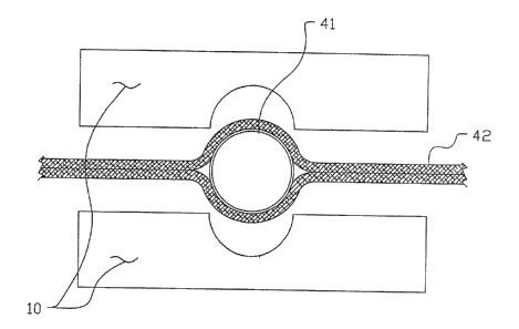
FIG. 4 shows a plan view of a pair of hot bars 10,
positioned for sealing use, between which is positioned a
fitment tube 41 between flexible film layers
lla
~~~~~s~u
PATENT
Case No. 41880
42 ready to be sealed together,upon the pair of hot bars 10 being pressed
together under pressure.
FIG 5 shows an isometric view of the flexible film pouch 50 of the
present invention having side seams 51, bottom seam 52, fitment tubes 53
sealed at top seal 54.
Although the illustrative embodiments of the present invention have
been described herein with reference to the accompanying drawings it is to be
understood that the invention is not limited to those precise embodiments, and
that various other changes and modifications may be effected therein by one
skilled in the art without departing from the scope or spirit of the
invention.
12