Note: Descriptions are shown in the official language in which they were submitted.
'PC~ 9 1 /0 ~ 968
~0 ~ecember lYi2
O ~
METHOD OF FORMING OPTICAL FIBRE GRATINGS
This invention relates to a method of forming two or more
Bragg gratings in an optical fibre waveguide.
In this specification the term ~optical" is intended to
refer to that part of the electromagnetic spectrum which is
generally known as the visible region, together with those
parts of the infra-red and ultraviolet (UV) regions at each
end of the visible region which are capable of being
transmitted by dielectric optical waveguides such as optical
fibres.
There is considerable interest in exploiting
photosensitivity in germanosilicate optical fibres for
application in the areas of optical communications and
sensors. The first reported permanent optically-induced
changes of the refractive index of optical fibres was by K.O.
Hill, Y. Fujii, D.C. Johnson and B.S. Kawasaki,
"Photosensitivity in Optical Fibure Waveguides: Application to
Reflection Filter Fabrication" Appl. Phys. Lett, 32, 647
(1978). In their experiment, coherent radiation at 514.5nm,
reflected from the fibre ends, generated a standing wave in
the fibre which induced a periodic refractive index change
along its length. This formed a high reflectivity Bragg
grating in the fibre which peaked at the wavelength of the
incident beam. Since then, numerous studies into the grating
growth mechanism and photosensitive fibres have been carried
out - see for example D.K.W. Lam, B.K. Garside,
"Characterisation of Single-Mode Optical Fibre Filters" Appl.
Phys, Lett, 20 440 (1981) and J. Stone, J. Appl. Phys., 62
4371 (1987). However, the mechanism which results in the
30 perturbation to the refractive index of the fibre core is not
fully understood. The spectral region where the fibre is
photosensitive has been found to range from the UV to around
700nm.
The potential applications of fibre gratings are numerous.
For example, in telecommunications applications, tunable
integrated fibre gratings, externally written with a UV laser,
may be used for spectral control of fibre lasers. B.S.
I*~d K~n~d~rn Pa~n~ r~ r ~, -; ~~
p~ na~iQ,~ A~- j3. ,~
P~ B 91 /01968
-3 ~.~.~ ~
- 2 - ~ 4 2
Kawasaki, H.O. Hill, D.C. Johnson and Y.Fujii, in an article
entitled "Narrow-band Bragg reflectors in optical fibres",
Optics Letters Vol 3 No.2 August 1978, pp 66-68, note that an
important property of the grating formation process is the
extent to which the filter response can be tailored. For
example, one method of forming a complex filter is to
superimpose two or more simple band-stop characteristics in
the same fibre by illuminating the fibre with different
wavelengths of light either simultaneously or consecutively.
Another known method of forming the Bragg gratings is by
side-writing the gratings by interfering two coherent
radiation beams at an appropriate angle. The pitch of the
grating is determined by the angle of intersection of the two
beams, so different grating pitches can be formed by adjusting
this angle.
According to the present invention a method of forming two
Bragg gratings in an optical fibre is characterised in that a
different longitudinal stress is applied to the fibre before
optically writing each grating, all the gratings having the
same Bragg condition at the time of writing.
The present invention provides a method of writing two or
more Bragg gratings without the need for multiple wavelength
illumination.
The method of the present invention exploits the fact that
optical fibre can, theoretically, be linearly strained by up
to 20%. If a photorefractive fibre, length l, is illuminated
by a light from a laser of wavelength Ao~ this will result in
a grating of period of about A0/2neff, where neff is the fibre
mode refractive index. If the fibre is now stretched by ~l,
then, when illuminated, a grating of the same pitch, i.e. the
same Bragg condition, as before will be written. When the
fibre is allowed to relax to its unstressed, normal length
after writing, the pitch of this second grating will be
slightly smaller than the first grating. For the case of a
reflection filter, the second grating has a peak wavelength
which is smaller than the writing wavelength. This can be
extended to providing several different pitch gratings in the
same fibre.
~ .
g ~m Pat~
T Intern~tional Applicaric, ~ iJ
PGTI~B 9 1 / ~ ~ 9 ~ 8
3~ ~sÇe ~ er1992
~ _ 3 _ ~ 4 2 ~
If, for example, there are two gratings of different
period in the fibre; then, if it is assumed that they have
some relative phase relationship, the index modulation in the
fibre is effectively given by the superposition of the two
index modulations. This is given by
neff (z)=AIcos ( (kl+k2)Z)cos ( (k,-k2) Z)
where kl and k2 are the wave numbers of the two gratings, Z is
the propagation direction, and Al is the amplitude of the
refractive index perturbation. At present, it is the second
modulation term that is of interest and it can be assumed that
the first term, which is a high frequency term, is a constant.
(This high frequency term can in principle be used as a short
wavelength reflection filter). The index modulation is
therefore now given by
neff(z)=A2cos((kl-k2)z)
From this expression, it can be seen that, by choosing the
periods of the two optically-written gratings, a resultant
grating of any period can be generated. The frequency
difference grating written in the fibre is of particular
interest in applications such as SHG, polarisation conversion
and mode conversion, as it allows the necessary phase matching
conditions to be met for these processes. The actual
operating wavelength depends only on the difference in the
values of kl and k2, and not on the actual write wavelength
itself. For example, a simple calculation shows that the
fibre would have to be stretched by approximately 2% if it is
to be used for phase matching in SHG. Even smaller changes in
fibre length would be required for polarisation and mode
convertors. These fibre length changes should be easily
attainable in the fibre currently being used in experiments.
It may also be possible to write reflection gratings for
use at the telecommunications bandwidth of 1.3-1.5~m if the
fibre can be stretched by approximately 10%. This is still
within the theoretically predicted change; but, due to defects
in the manufacture of the fibre, it is not clear whether it is
possible to do this. Assuming that it may be done, this would
allow high reflectivity, small bandwidth gratings to be
written in the fibre. It would also be possible to write
PC~JG~ 9 1 f O 1 ~ 6
3 0 1; e~em~er 199
~~ ~ 4 ~ ~ ~ ~ 3 ~ ~ ~
several gratings in the fibre, which would allow pulse
generation and shaping of incident laser light.
A convenient method of applying the different longitudinal
stresses to the fibre to produce the different strains, is to
clamp one end of the fibre, and to apply the stress by means
of a piezo-electric translation stage clamped to the other end
of the fibre. Clearly, other stressing means may be used such
as a clamped micrometer attached to the fibre end instead of
the piezo-electric translation stage.
Other writing techniques can be used, for example wrapping
the fibre around a cylinder, the stress being applied to the
fibre by varying the radius of the cylinder by a piezo-
electric expander. Also the fibre could be coated with a
piezo-electric cladding, and the strain could be changed by
varying the applied voltage.
The invention is applicable to external grating writing
methods, as well as to gratings written by launching an
optical signal down the fibre.
An embodiment of the present invention will now be
described, by way of example, with reference to the
accompanying drawings, of which,
Figure 1 is a schematic diagram of apparatus specifically
designed for carrying out the method of the present
invention;
Figure 2 is a graph of the reflectance and transmittance
of a fibre grating as a function of relative strain; and
Figure 3 is a graph of the reflectance and transmittance
of a fibre having two gratings as a function of applied
strain.
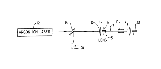
The experimental apparatus used to write gratings in
single mode germanosilicate fibres at 514.5nm is shown in
Figure 1. A fibre 2 with a radius of 0.9~m and a ~n of 0.012
has one end 4 enclosed in a glass ferrule 5 and clamped with
a clamp 6. The other end 8 of the fibre 2 is connected to a
35 piezo-electric translation stage 10, which allows the length
of the fibre, about equal to 50cm in this case, to be changed
by up to by 20~m. The gratings are written by coupling an
argon ion laser 12 lasing at 514.5nm into the end 4 of the
. ~ ;J~ ',*~ 3sfi~ S~ /i f
j f~ e,n~ti~n~ ppiic~tion
. ~ . .
P~T/~ 9 1 / ~ 1 9 6
~9 ~cem~ i99Z
- 5 -
fibre 2 via a partial reflector 14 and a lens 16. The signal
exiting the end 8 of the fibre 2 during writing of a grating
is focussed onto a photodetector 18. The increasing signal
reflected by the grating as it is written into the fibre 2
exits the end 4 of the fibre 2, and is focussed by the lens 16
and reflected to a photodetector 20 by the partial reflector
14.
During the writing and reading of the grating, the
polarisation of the input and monitor beams are carefully
controlled.
The reflectance profile of the fibre 2 after writing the
gratings is obtained by launching 0.5mW of 514.5nm light into
the fibre, and then stretching the fibre using the
piezo-electric translation stage 10.
Figure 2 shows the low power reflectance/transmittance of
a typical grating formed in the fibre after 250mW, from the
single mode argon ion laser 12, is launched into it for
approximately two minutes. This gives the
reflectance/transmittance profile of the grating as the Bragg
condition of the grating linearly changes with strain. From
this data, the grating was found to have a peak relativity of
70% and a bandwidth of 482MHz. The profile of the grating
shown in Figure 2 is similar to the sinc2 reflection profile
normally associated with Bragg reflectors.
By changing the strain applied to the fibre 2 before
writing a grating, a further three gratings can be optically
written in the same fibre, each with a peak wavelength
separated by 46GHz. By varying the strain applied to the
fibre, the four gratings written in the fibre can be scanned
30 through.
Figure 3 shows the transmittance and reflectance, as a
function of applied strain, for a probe signal of 514.5 nm
from the argon laser 12 for a strain range which scans through
two of the four gratings.