Note: Descriptions are shown in the official language in which they were submitted.
2~3~3~
CH ILD- PROOF TABLET DI SPENSER
"'
~ BACXGROUND AND PRIOR ART
~.'
Many pharmaceutical products are marketed in the
form of tablets. Some of these tablets are relative-
ly small. As such, these small tablets are inconve-
nient to handle, especially by older persons who may
have reduced mobility in their hands. There is thus
a need for a dispenser for such tablets for conve-
nient handling thereof. Such dispenser should be
:
able to dispense the tablets one at a time. In order
to protect immature individuals from being able to
obtain tablets from such dispenser, it should be
child-proof in its operation. However, it should not
be so difficult to operate that the above older
individuals will be unable to dispense the tablets.
Tablet dispensers capable of dispensi.ng such
~ablats ona at a ~ime ara known in ~he art. U.S.
.,774t470; 4,35~,619 and ~,492,316 are repre~entativa
MS-1692
~ '
; , . - :.: , , .-, : . .: . .:
,`, . , :, , . :- . : : : :: :
21~93~
-- 2
of such prior art. These prior art dispensers,
however, do not have any child-proof or child-
resistant features. Dispensers or containers having
features which make them difficult for small children
to open are also known in the art. U.S. 3j888,350
and 4,561,544 are representative of such prior art.
There is no known prior art that discloses or sug-
gests the unique combination of a tablet dispenser
capable of dispensing tablets one at a time and which
is also easy to operate while at the same time being
child-proof.
SUMMARY OF THE INVENTION
In accordance with the present invention, a
child-proof dispenser for pharmaceutical tablets
capable of dispensing such tablets one at a time is
provided which comprises an enclosed tablet storage
chamber formed by first and second vertical side-
walls, third and fourth vertical endwalls/ a top
member and a bottom member having an opening therein
located near the fourth vertical endwall, said
~peniny havin~ dimenslons to allow any ~ablets stored
ln ~aid chamher ~Q pa~ therethrollgh in a vertical
, ~
. ~ M~-169~
~'3~37
single-file column, said bottom member comprising a
ramp which slopes downwardly from the third vertical
endwall toward the fourth vertical endwall and which
has side portions which slope inwardly from the first
and second vertical sidewalls, a housing member
attached to at least some of the walls of said
chamber, a drawer member and a locking member, said
housing member supporting said drawer member and said
locking member, said locking member having at least
one detent means attached to a flexible arm, said
drawer member having an open-topped receptacle
therein with a horizontal extension means coplanar
with the open top of said receptacle and at least one
detent means, said receptacle having dimensions such
as to retain a single tablet in a vertical position,
said drawer member capable of moving from a first
position wherein said drawer receptacle communicates
with said opening in said storage chamber bottom
member allowing a single ~a~let to drop into said
receptacle and wherein said locking member detent
means is in locking relation to said drawer member
detent means to a ~econd position wherein saicl drawer
receptacle i~ outsicle o~ ~aid dispen3er hou~ing
membe.r allowing access to d table~ in said receptacle
MS-1692
''~
.. , . : , :
~9~3P~
- 4
and said horizontal extension is located beneath said
storage chamber bottom member opening to prevent any
further tablets from passing through said opening,
said locking member flexible arm capable of being
moved by digital pressure to move said locking member
detent means out of locking relation with said drawer
member detent means to enable said drawer member to
move from said first position to said second posi-
~`~ tion.
~ ~ .
`~ DESCRIPTION OF THE DRAWINGS
Fig. l is a vertical cross-section of a dispens-
er of the present invention wi~h the dispensing
drawer in a first closed position.
Fig. 2 is a vertical cross-section of the
- dispenser with the dispensing drawer in a second open
position.
Fig. 3 is a vertical cross-section of a portion
of the storage chamber bottom member ramp and a
,.,.~, ~
tablet contained therein along the plane 3-3 in Fig.
1 .
Flg~ 4 i~ a horizon~al cro~sectian a~ portians
Oe ~ha dxawer mem~er and ~e ~lrst locking member
~S-1692
-.~
. . : ~ : . . . : :
~3~3~
along the plane 4-4 of Fig. 1 with such members in
locking relation.
Fig. 5 is a view similar to that of Fig. 4 with
such members not in locking relation.
Fig. 6 is a vertical cross-section of a portion
of the drawer member receptacle and stored tablet
along the plane 6-6 of Fig. 2.
Fig. 7 is a vertical cross-section of a portion
of the housing member and of the first and secon~
locking members with such locking members in a mating
relation.
Fig. 8 is a horizontal cross-section taken along
plane 8-8 of Fig. 7.
Fig. 9 is a view similar to that of Fig. 7 with
the first and second locking members not in mating
relation.
Fig. 10 is a horizontal cross-section along
plane 10-10 of Fig. 9.
Fig. 11 is a vertical cross-section o~ portions
of the second locking member and the housing along
the plane 11-11 of Fig. 10.
~ MS-169
:: .
;' ':
2~3~37
-- 6
DESCRIPTION OF THE INVENTION
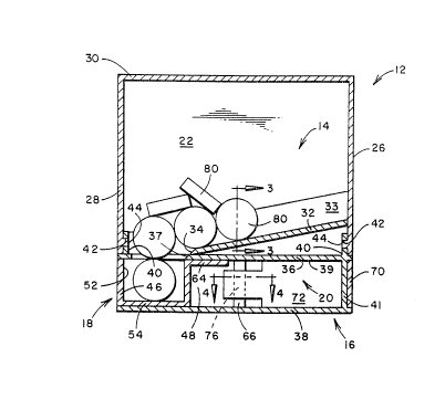
As shown in Figs. 1-4, the tablet dispens~r 12
of the present invention compxises a tablet storage
chamber 14, a housing member 16, a drawer member 18,
and a first locking member 20. The enclosed storage
chamber 14 i~ formed by first vertical sidewall 22,
second vertical sidewall 24, third vertical endwall
26, fourth vertical endwall 28, top member 30, and
bottom member 32. Bottom me~ber 32 slopes downwardly
from endwall 26 toward endwall 28 in the form of a
ramp which terminates short of such endwall 28 to
form an opening 34. Such opening forms the bottom
exit from chamber 14. ~ottom member 32 also has
vertical portlons or sidewalls 33 and 35 which slope
inwardly ~rom the chamber sidewalls 2~ and 24 toward
the bottom 32 as shown in Flg. 3.
Housing membex 16 is ~ormed as a unitary member
having an upper horizontal portlon 36 and a lower
horizontal portion 38 forming a channel 39 there-
between. Portlon 36 has an opening 37 located
~hereln whlch i ~ in alignment wlth and conlmunlcates
with opening 3~ in bottom membex 32. Portion~ 36 and
MS-1692
,, .
'~:
:: : . : : , : .: .,.: : . : .
_ 7 _ 2~3~7
38 are connected by spacer means 41. Housing member
16 is attached to at least some of the walls of the
storaye chamber 14 in any convenient manner. One
manner is shown in Fig. 1. Housing member 16 can
have vertical extensions 40 with transverse openings
42 therein. Endwalls 26 and 2~ can have horizontal
detent~ 44 which extend into and mate with openings
42.
Drawer member 18 Aas a vertical endwall 46 and
first vertical sidearm 48 and second vertical sidearm
attached there~o. Sidearm 48 has a vertical
detent means 66 located alo~lg the inner end thereof,
and sidearm 50 has a vertical detent means 68 located
along the inner end thereof. Member 18 has a recep-
tacle 52 formed therein with a bottom 54, a vertical
endwall 56 and a top opening 58. Receptacle 52
preferably has vertical sidewalls 60 and 62 which
slope inwardly from the kop opening 58 toward the
bottom 54 as shown in Fig. 6. Drawer member 18 has a
horizontal extension 64 which is coplanar with top
openinq 58. Drawer member 18 is located in the
channel 39 be~we~n top and bo~tom por~io~ 36 and 38
o~ housing 16 and ls ~upported thereby. When drawer
member 18 i~ loca~ed in lt3 firsk position, as ~hown
MS 1692
~.
2~93~
-- 8 --
in Fig. 1, the top opening 58 communicates with and
is in alignment with openings 34 and 37 of the
chamber bottom member 32 and top portion 36 of
housing member 16, respectively.
First locking member 20 has a vertical endwall
70 and first flexible vertical sidearm 72 and second
flexible vertical sidearm 74 attached thereto.
Sidearm 72 is narrowed at its inner end with a
vertical notch or detent means 76 therein along the
outer surface thereof. The inner end of sidearm 72
also preferably has an inwardly curved portion 73.
Sidearm 74 is narrowed at its inner end with a
vertical notch or d~tent means 78 therein along the
outex surface thereof. The inner end of sidearm 74
also preferably has an inwardly curved portion 75.
First locking member 20 is located in the channel 39
between top and bottom portions 36 and 38 of housing
16 and is supported thereby.
When drawer member 18 is in its first position
shown in Fig. 1, the detent means 66 and 68 thereo~
are in locking mating relation wi~h the detent means
76 and 78, respectively, of first locking member 20.
- This is ~hown in Flg. ~. ~hi~ lockln~ .relation
prevents any movement o~ the drawer member 18. When
MS-lfi92
.: ~
;
;: .
: . , . . :
9 2~3~3~
inwardly directed digital pressure is applied to the
outer surfaces of sidearms 72 and 74 of first locking
member 20, the detent means 66, 68, 76 and 78 are
moved out of locking mating relation as shown in Fig.
5. The flexibility of the sidearms 72 and 74 may be
selected such that the digital pressure necessary to
move the detent means out of locking relation is more
than that of a child but not more than that of an
elderly patient. In this situation, drawer member 18
can be pulled or moved out of housing member 16 by
digital pressure to the second position shown in Fig.
2. It thus requires a combination of two movements
to dispense a tablet. The locking member must be
pushed in and the drawer must be pulled out. A child
would normally not comprehend this. In this second
position, the horizontal extension 64 of the drawer
1~ at least partially covers th6 opening 37 of
housing 16. When drawer 1~ is pushed or moved again
inside housing 16 to its flrst position, the curved
ends 73 and 75 of sidearms 72 and 74 ena~le such
sidearms to easily slip over the detent means 66 and
68 o~ ~he drawqr 18 to allow ~uch detant mean~ to
a~ain mato with ~h~ deton~ m~an~ 76 and 78 o~ the
~ir~t locking membor 20.
.; .
MS'-1692
~' ~
.,
2~93837
- 10 -
In order to use this dispenser for dispensing
tablets, the housing 16 is separated from the storage
chamber 14 and such chamber is inverted with the top
` 30 on the bottom. The storage chamber 14 is then
filled with an appropriate amount of tablets. The
housing 16 is then attached to th2 storage chamber
14, and the combination is inverted to the normal
position shown in Figs. 1 and 2. The tablets 80 will
then flow by gravity to cover the bottom member 32.
The sloping sidewalls 33 and 35 of the bottom member
or ramp 32 will maintain the tablets 80 in a vertical
single file order along the ramp 32. The dimensions
of the openings 34 and 37 of the bottom member 32 and
housing 16, respectively, are such as to allow the
tablets 80 to pass therethrough in a vertical single-
file column into the receptacle 52 of drawer 18. The
; dimensions of receptacle 52 are such as to maintain a
single tablet in a vertical position. When drawer
18 is moved from its first position inside houslng 16
to its second position outside of housing 16, the
horizontal extension 64 prevents any further tablets
from passing through opening 37 o~ housLng 16. The
di~penser can then be inve;rted to ~llow the ~ablet to
~ ~all ou~ o~ r~ceptale S2 in~o the hand o~ the
:
MS-1692
: . . . .
.. .. . .
.
~ , ... . ~ .
2 ~ ~ c~
patient who can then consume the tablet. ~he dis-
penser .is then placed in its normal upright position,
the drawer 18 is then pushed in to its first position
wherein a new tablet is allowed to fall into recepta-
cle 52 for further dispensing in the above-described
manner.
~ modification of the child-proof feature of the
dispenser is shown in Figs. 7-11. A second locking
member 82 comprising a horizontal plate 84 and a
vertical locking extension 86 is located beneath the
housing lower portion 38 with extension 86 passing up
through an elongated opening 88 in housing portion
38. Extension 86 has detent means 90 which mate
against housing portion 3~ to allow the housing
portion 38 to support the second locking member 82.
Extension 86 also has sloping surfaces 92. The
sidearms 72 and 74 of the first locking member 20
have horizontal extensions 94, each having sloping
surfaces 96 which are complimentary to the sloping
surfaces 92 of extension 86. When the second locking
member 82 is in its first position as shown in Figs.
7 and 8, extension 86 mates against extensions 94 to
prevent sldearm~ ~2 and 74 from beinq moved lnward in
khe mannqr shown in Flg~.4 and 5 to allow th~ drawer
.:,
MS~1692
' . '
':
~ ':
3 ~ 't~
- 12 -
18 to move out o~ the housing 16. When the second
locking member 82 is moved to its second position as
shown in Fi~s. 9 and 10 by applying digital pressure
thereto, extension 86 no longer mates against exten-
sions 94, and the sidearms 72 and 74 are freP to
move. Plate 84 of the second locking member 82
preferably has an indentation 98 along its lower
outer surface 99 to assist digital pressure in moving
member 82 back and forth.
All of the components of this dispenser can be
conveniently formed from appropriate organoplastic
materials. It is preferred that top member 30 be
transparent so tha~ the supply of tablets in the
storage chamber can be observed.
This tablet dispenser has the advantages of
being capable of dispensing tablets one at a time and
being easy to operate while at the same time being
child-proo~.
The tablet storage capacity of this apparatus
can be varied by using storage chambers of different
sizes. The lower dimen~ions of the chamber 14 can be
malntained at con~tant value~ to ea~lly mate again~t
hQu~ing 16 while the height~ o~ ~he vertiaal ~ide-
wall~ a~d endwalls could be o~ an~ desired value~.
MS-1692
,. . . . . -
. : . : : ~, , :
~ .