Note: Descriptions are shown in the official language in which they were submitted.
CA 02093915 2003-11-12
- 1 -
Title: A DISPENSER, PREFERABLY FOR SUSCEPTIBILITY TEST DISCS
Field of invention
This invention concerns a dispenser for flat objections, and
relates to a dispenser for dispensing flat objects from a
stack of similar objects housed in a cartridge, and has
particular application in dispensing susceptibility or
sensitivity test discs impregnated with a substance such as
an antibiotic.
Background to the invention
In sensitivity testing of samples of organisms, sensitivity
discs impregnated with different substances, such as various
antibiotics, are dispensed onto the surface of a culture
medium, e.g. a thin layer of agar gel, in a receiving
container such as petri dish. Such discs typically comprise
a circular piece of absorbent material such as blotting
paper, about 0.5mm thick, and are conventionally supplied in
a stack, e.g. of 50 discs, in an elongate cylindrical
cartridge, with the discs biased to an exit end of the
cartridge by means of an internal coil spring.
A variety of dispensers are known and commercially available
for dispensing discs from such cartridges, including a
variety of different designs of dispensers for
simultaneously dispensing a plurality of discs in ~
predetermined pattern from respective cartridges. See, for
~-w ~3ioszo~ ~~;r>c~~~2~~3~~s
_ 2 _ ~~~J~~~
example, US.4042145 and US.~~36047.
The invention aims to provide a nove:L construction of
dispenser for flat objects that is robust and reliable in
operation.
Summate of the invention
Tn accordance with the present invention, there is provided'
a dispenser for dispensing flat objects from a stack of
similar objects housed in a cartridge, comprising: a body
portion; a plurality of receptacles within the body portion,
each receptacle being adapted to receive a respective
.object-containing cartridge; a plurality of dispensing
ports, one associated with each receptacle; a plurality of
tampi~ag pins, one associated with each dispensing port, for
tamping an object through the associated dispensing port;
transport mesas arranged f or rotary motion to transport an
object from each cartridge in a receptacle to a dispensing
position in alignment with the associated tamping pin and
dispensing port; and retaining means fixed with respect to
the receptacles, far retaining the objects in position
during transport from a cartridge to the associated
dispensing position.
For convenience, the explanation which follows assumes 'that
objects are to be dispensed in a downwards direction, as
will generally be the case in practice, bwt it is to be
understood that the: dispenser could also be used to dispense
articles upwardly. Reference to arientation in the
following eacplanation should thus be canstrued~accordingly.
The dispensing porter are preferably initially rotationally
offset with respect: to the associated tamping pins, and in
.. ~'V~ 93/6207 ~ ~ ~ ~ ~ ~ ~ ~~rWli9z/~,'7~6
- 3 -
this case the transport means conveniently cornprises a
transport plate arranged for rotary motion.
The dispensing ports are preferably carried by the transport
plate, e..g. by being integrally formed therewith, extending
d.ownwardly'from the lower face of 'the plate. In this case,
the lowermost object in a cartridge is initially located in
position in an associated dispensing port, and on movement
of the transport plate the dispensing port and associated
object are moved into alignment with the associated tamping
pi.n, ready for tamping. The dispensing ports axe preferably
dimensioned to have a diameter slightly less than the
diameter of the discs to be dispensed so that the discs will
sit on the top of the ports.
The transport plate preferably includes means for retaining
and guiding the object in position during transport
conveniently the~upper face of the transport plate.is formed
with an upwardly extending.rim to engage the base of the
associated cartridge and to receive the lowermost object in
the cartridge, and includes an adjacent pushing face to
engage an edge of the object and push the object with the
transport plate on transport movement.
The retaining means conveniently comprise~a retaining plate,
located above the transport means, t0 Contact the, upper
w faces of the objects during transport. The retaining plate
is preferably in the form of a disc with a first~series of
apertures through which ends of the cartridges pass and a
second series of apertures, interposed between the first
- series, through 'which the tamping pins piss.
The tamping pins are conveniently actuated b:: a tamping
plate arranged for downward movement in the body portion
~_ 19~ro~zo7 . ~ ~ ~ ~ ~ .~ J ~c~~f~~~2/or75~
when the objects are in appropriate dispensing positions.
The dispenser conveniently includes a plunger actuator
mechanism for causing appropriate movement of the
components. The mechanism desirably includes a rotary
actuating tube, fixed with respect to the transport means
and 'including one or more cam slots each for receiving an
actuating pin fixed with respect to a plunger. The or each
slot is shaped such that downward movement of the plunger
relative to 'the actuating tube causes initial rotary motion
of the actuating tube and hence of the attached transport
means, moving objects to the dispensing position.
Subsequent downwards movement of the plunger causes vertical
movement of the or each pin, in a vertical portion of the
associated slot, with the pins engaging the dispensing plate
and causing downwards dispensing movement of the tamping
pins, resulting in dispensing of the objects, generally onto
a receiving surface therebelow.
Such cam slots preferably include three sections: a first
slightly inclined portion designed to give a good mechanical.
advantage on iwitial movement where the highest load is
required; a second more inclined portion for causing
rotation under conditions in which load is less; and a third
vertical portion for downwards dispensing actuation of the
' tamping pins. _
The plunger is conveniently biased to return to its initial,
start position, e.g. by means of a suitable compression
spring.
A separate return spring is preferably associated with the
tamping plate, iiesirably located between the tamping plate
and retaining plate. Both of these plates are fixed in
vv~ ~~io6x~~ ~ ~ ~ ~ ~ ~. ~ ~~.~v~r~zioa7~~ .
- 5 -
rotation so that no twisting of the spring occurs during
use,
The plunger is desirably fitted with a large end cap to
facilitate ease of operation.
The tamping pins are preferably spring mounted so as to have
~a degree of vertical resilience, to accommodate
irregularities in a receiving surface.
The dispenser enables simultaneous dispensing of an object
from. each dispensing-port in a predetermined pattern.
Typically six or.eight dispensing ports are provided in a
circular arrangement.,. but other arrangements eg twelve
dispensing ports are also possible.
A .g~aiter~, conveniently of resilient corrugated material, is
desirab7,y located around the upper portion ofwtlie plunger,
between the body portion and end cap, to prevent ingress of
dirt to the dispensing mechanism and possibly also for
aesthetic reasons.
The dispewser finds particular applicatian~in the dispensin.g~
of sensivity or susceptibility test discs .impregnated with
substances such as antibiotic's. As noted above, such discs
are commonly supplied in a cylindrical cartridge in which a
stacl~ of ,circular discs o.f ~ blotting paper, each. about 0 .5mm
thick, is spring biased to a dispensing aperture at one end
pf~ the cartridge. Such cartridges are of standard
configuration and are widely available commercially.
~elaabxlity of a d3.spensing device is important in such
applications: on each~dispensing action it is essential that
a disc is di.spenaed from each cartridge, otherwise the test
o' '~ 93/06207 ~ ~ ~ ~ ~ ~ ~ 1P~~/~1892/Q17S6
6
will be ineffective and the samples is thus wasted. ,
Antibiotic disc dispensers in accordance with the present
invention have been found to funcf:ion very well. in practice.
They are easy and reliable to use and there was found to be
little or na tendendy of the mechanism to stick in use,
unlike certain prior art designs.
The dispenser may include a removable base for height
adjustment purposes. The base preferably has a stepped
upper face adapted to be engaged by inwardly extending
longitudial ribs in the body portion such that relative
rotation of the body and base results in adjustment in the
height of the base above a surface. The outer face of the
base preferably includes a plurality, eg 4, of series of
v~rticai grooves or slots, so that the body can be
positively located and retained on the base in any desired
position of height adjustment by sliding the body downwardly
on to the base with each rib engaging a selected groove of
the associated series. The arrangement enables height
adjustment to be effected without the need for tools. Such
a height adjustment arrangemewt enables 'the dispenser to be
adjusted to accommodate, for example, different gel
thicknesses in petri dishes.
P~iore than one base may be provided for a particular
dispenser, intended for differewt end uses, for example with
petri dishes of different diameters.
The disgenser may be provided with a casing, cahich is
preferably of t:wo-part form comprising a base and a top
interconnected, e.g., by a bayonet fit. 'rhe casing base may
include,internal formations such that the casing can
accommodate daL:ygensers when fitted with height adjustment r
'V1'~ 93/06207 T~Z;"~"/~~Sf32/0'~7~~
_
bases of different sizes. The casing cover preferably
includes a large flat top area for labelling purposes. A
dessicant material may be located in the casing, eg in a
cavity in the base, in appropriate conditions, far example
for use with dispensers containing cartridges of
susceptibility discs.
A preferred embodiment of the invention in the form of a
dispenser for use with cartridges of suscep~tib~.lity test
discs bearing antibiotics will now be described, by way of -
illustration, and with reference to the ac.companing drawings .
in which:-
Figure 1 is a side view of the dispenser, shown partly cut
away;
Figure 2 is a top plan view of the dispenser;
Figure 3 is a diagrammatic exploded view, to an enlarged
scale, of certain components of the dispenser;
Figure 4 is a partial sectional view .along line X.-:; i.n
Figure 2, with the mechanism in a start or rest position;
Figure 4a is a frag.men~tary view illustrating the position of
an actuating pin and cam slot in.the condition of Figure 4;
Figures 5 and 5a are views similar to Figures ~a and 4a, with
a mechanism in an intermediate position; .
Figures 6 and 6a are views similar to Figures 4 and 4a, with
. the mechanism in an end or dispensed position., additionally
illustrating a petri dish;
~ 93/0620') . ~ ~ ~ ~ ~ ~ ~ ~''~'/~~~2/Ol%S6
g _
Figure r is a diagrammatic view illustrating the position of
various components, with the mechanism in the start or rest
position;
Figure 8 is a view similar to rFigure 7, with the mechanism
in an intermediate, transporting position;
Figure 9 is a view sirnilar to Figure 7, with the mechanism
in an intermediate position corresponding to that shown in
Figure 5;
Figure .10 is a view similar to Figure 7, with the mechanism
in the end or dispensing position; and
Figure 11 illustrates a casing with the dispenser located
therein
Detailed Description of the Drawings
The drawings illustrate a dispenser for dispensing
susceptibility test discs bearing reagents such as
antibiotics from cartridges of a,f~rm that is widely
available commercially.
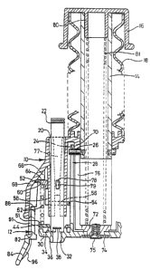
z~tith reference to Figures t and 2, the illustrated dispenser
comprises a body portion 10 in Which the dispensing
mechanism is mainly housed; a removable base 12 :Eor height
adjustment purposes as will be described below; and an .
actuating plunger 1~k Fitted with an end cap 16 and
surrounded by a a.-esilient corrugated gaiter 18. Body.
portion l0 includes six similar tubular receptacles 20 each
f or receiving a cartridge 22 (Figure 4) containing a stack
of sensitivity d~acs engaged by a spring biased plunger and
urged towards a dispensing aperture. The disc~containing
'°'4) 93/06207 ~'~Cf/aG~312/01756
_ g _
cartridges are of conventional constructiow , e.g.. as
supplied by Oxoid Limited, Basingstoke, Hampshire, England.
Referring to Figures 3 and 4, the dispensing mechanism
comprises a rotatable actuating tube or sleeve 24 of larger
diameter than plunger 14. Sleeve 24 is connected to the
lower end of the plunger 19 by means of four actuating, pins
26 extending radial~.,y outwardly from the plunger 14 and
engaging in respective cam slots 28 machined in the sleeve'
24. Each slot 28 includes an upper portion 2.8a o.f shallow
slope, and intermediate portion 28b of steeper slope and a
lower vertical portion 28c.
The lower end of sleeve 24 is formed integrally with a
revolving transport plate 30., The transport plate is of
generally annular configuration and includes 6 downwardly
extending dispensing ports 32 the upper end cf each of which
is partially surrounded by a part circular upstanding_rim
39. The dispensing ports, are dimensioned to have.a diameter
slightly .less than the diameter discs 3a to be dispersed so
that the discs sit in the_top of the port. Rimes-34 engages
the base of an associated cartridge 22 and receives
retaining lugs 36 of the cartridge ana also the lower most
disc 38 retained thereby in the cartridge (Figure 4). A
respective upstanding rib -40 extends from each rim 34 and
terminates ia~ a front face 42 for engaging the edge of an
w adjacent disc 38 and pushing the disc to move, with plate 30
on rotation, as will be described below.
A retaining. plate 44 is located above the transport plate
30. Plate ~4 is of generally annular configuration and w
includes six larger circular apertures 45 through which
cartridges 22 e:Ktend, interspersed w.it:~ six smaller circular
apertures 48 each for receiving a respective tamping pin S0.
~'C°fl~F~92/0175b
~ 93/0G207
--
Plate 44 includes an upstanding peripheral rim 51.
The tamping pins 50 extend downwardly from a dispensing
plate or plunger bearing plate 52. Plate 52 includes an
inner lower annular portion 54, with six circular apertures
5o through which lower portions of the cartridge-receiving
receptacles 20 pass; an upstanding cylindrical side wall
portion 58; and an outwardly extending flange portion 6Ø
The tamping pins 50 are secured to the underside of portion
54, spaced midway between adjacent apertures 50, and are
spring mounted to be resiliently displaceable to a limited
degree with respect to the plate 52, for reasons to be
described below.
A compression spring 62 is located between retaining plate
44 and flange portion 60 of c'iispensing plate 52 and acts to
'~ias~dispens~.ng plate 52 upwardly to the position shown in
Figure 4, in which flange portion 60 engages a shoulder
portion 64 on each of four stepped ribs 66 extending
inwardly from a lower, outer skirt porl~ion 68 of body
portion 10. Plate 44 and plate 52 are both rotationally
stationary during dispensing action, as will be discussed
below, sn that no twisting action is applied to the spring
62. .
Body portioaa 10 also includes an inner tubular por.tcion 70,
the upper end of whick~ surrounds plunger 14 with a sliding
f it, and the lower end of which carries a bearing member 72.
Bearing. member 72 fits iwto a circular opening in the centre
of transp~rt plate 30, being secured in place by means of
.washer 74 and screw 75, so as to permit relative rotation
between member 7~ (which remains stationary during operation.
of the dispenser) and transport place 30. Tubular portion
7G includes four elongate vertical slots 76 through which
~c~ 9mo6z~~ ~ ~~rm~~zio~7~~
- 11
the actuating pins 26 pass for vertical sliding movement.
The cartridge receptacles 20 are formed. in the body portion
10, and each comprises a slightly tapering cylindrical
.. aperture including a ta.peri:ng slot 77 down which is slid a
protruding locking peg ~78 on a cartridge 22. The slot
includes protruding teeth 79 far engaging in mating recesses
i:n the locking peg, for locating and lacking the cartridge
in position in the receptacle.
End cap l6 is.a push fit in the upper end of plunger 14,
with'an~insert 80 in the cap forming a tight friction f.it
within the plunger.~~ ' ' w
A compression spring 81 is located within the plunger 14 and
body portion 10, extending between cap insert 80 and end cap
72, and acts to bias the plunger upwardly to the start or
rest position shown in 1a'igure 4.
Base 12 includes a cylindrical upper portion 82 and a flared
7:ower skirt portion 84. t,pper portion 82 of base 12 is
dimensioned to fit within the lower portion 68 of body
portion 10.
The upper face of portion ~82 engages a lower shoulder 88 on
each rib 66. 1:'or height adjustment purposes, tha.s face
~incl.udes~four similarly stepped regions 90 as shown in
Figure 1.. A respective vertical groove or slot 91 in the
outer face of portion 82 is associated with each step of
region 90, so there are four series of varyin; 'length
grooves 91. Each rib 66 can engage in a select ed groove of
each sez~xes o.f grooves, so that the body portion can be
.postively located and retained in any desirvsc position of
height adjustment by rotating base 12 relative to body
'~ 93!06207 1?CT/G~392/01756
2Q~~~.~
- 12 -
portion 10 and sliding the bocis- portion downwardlf onto the
base with each rib engaging a selected groove of the
associated series of grooves. The arrangement enables east
adjustment of the height of body portion 10 and hence the
dispensing mechanism, enabling adjustment of the dispenser
to accommodate use with gels of different thicknesses. No
tools are required for this adjustment. Markings 92 (Figure
1) are provided on the base to indicate different height
positions.
Skirt portion 82 is dimensioned to fi~ around a petri dish
94, as spawn in Figure 6, with the side wall of the dish
engaging inwardly extending ribs 96 on the base skirt
portion. The dispenser may be provided with two alternative
bases, of different lower diameter, for use with petri
dishes of different standard.sizes, for example 90mm and
100mm. Petri dish 94 is shown containing a layer of agar
gel 95.
The dispenser is provided with a storage case 100, as shown
in Figure 11, comprising a base 102 and a cap 104 which are
releasabl~.~ secured together by a bayonet fitting. The ease
102 includes an upstanding internal~circular collar 106 so
that it~can accommodate dispensers fitted with both sizes of
base. The~smaller base engages the collar 106 as shown, and
the larger size base engages the case base side wall. A
sachet (not shown? containing a dessicant material may be
located in recess '107 in base 102. The cap 104 includes a
~.arger flat top 108 on which information can be,readil~y
marksd, e.g. on a removable !able.
The dispenser components are all made of opaque acetal, with
the.exception of 'the plunger which is of steel, but may be
of other metals. The base of the case is of opaque A~3S and
'~'fJ 93/06207 ~'~T/GB9~/01'75(>
- 13 -
the top of the case is of polycarbonate. The angled slots
2.8 are machined, but the components are otherwised formed by
molding .
The dispenser, without base, has~an overall height in the
rest position of about 130mm and an overall da.ameter of
about 100mm.
In use, six disc-containing cartridges 22 are located in the
six receptacles 20 and locked in position by use af~ locking
.. pegs 78.
Starting from the stationary or rest position as shown in
Figures 4 and 7, plunger 14 is depressed downwardly, by
applxing force to end cap 16. Dovmwards movement of the
plunger causes'corresponding downwards mavement of actuating
pins 2fi with consequential rotation of s.le2ve 2.4 as the pins
slide in the first inclined portions 28a of slots 28. This
causes corresponding rotation of transport plate 30 in an
anticZackwise direction as seen in Figure 3,. with the
remaining components remaining stationary. This movement
causes plate 30 and discs 38 carried thereby to rotate.
relatiue to the remaining components, with the effect that
the discs are rotationally moved from being below thp
cartridge in a direction towards the associated tamping pins
50 as shown in Figure 8. The discs 2z are retained in
position in plate 30 between rims 34 and faces 42, with.the
discs being positively hocated by, these components. .
~tetaining plate 44 an tap of the transport plate 30 acts to
prevent movement of the discs relative. to the transport
plate on movemewt. During such movement, the discs sit in
the top of the associated dispensing port 32, which is
dimensioned to have. a diameter slightly less. than that of
the discs.
o~"~ 93/06207 ~P~C/G~~392/OI756
- 14 -
'.transport plate 30 rotates on depression of plunge: 14 until
the components reach the position shown in Figures 5 and 9,
in which the discs and dispensing ports 32 are aligned wit's
the associated tamping pins 50.
The initial part of this rotary movement involves 'the
highest load, so the first portion 28a of each slot is
gently sloping to give a good mechanical advantage. The
intermediate portion 28b of each slot is more steeply
sloping as in this part of-the movement there is no need for
such a high mechanical advantage.
As shown in Figure 5, in this intermediate position, the
actuating pins 25 now engage f~.ange~~portion 60 of dispensing
plate 52, and farther downwards movement of the plunger
causes downwards movement of the dispensing plate, pushing
the tamping pins 50 through the dispensing ports 32 to expel
the discs. No rotary motion takes place in this part of the
- dispensing action as the slot portions 28c are vertical.
Zn trae end or dispensing position shown in Figure o and 10,
the dispensi:.g plate 52 engages retaining.plate 4h acd
further downwards movement is not possible. In this
positions the tamping pins.50 project slightly from the
dispensing ports and act to 'tamp the discs 22 firmly onto
the surface of the gel 95 in the petri dish 94.
Before dispensing, the height of the dispenser is adjusted
by usa of base 12r as described above, to be suited to the
thicknesses of the particular gel.
The spring mounting of the tamping pins 50 mean that the
device caa accommodate some degree o'' irregularit'~ in the
~V~ !~3/OH2~7 ~ ~~'f/G~39~/01756
1S -
gel thickness.
On release of downwards force from the plunger 14, the
return springs 52 and 81 act to return the components to the
start position as shown in Figure 4. The device is then
ready for. reuse to dispense the next discs from the
cartridges.
when a cartridge is empty, the plunger therein protrudes
slightly therefrom and engages in the transport plate 30
preventing rotation thereof thus effectively locking the
dispenser and preventing use.
If a respective cartridge is not located in each receptacle,
the~dispenser will nevertheless still function, but in
practice the.dispenser would always be used with a.cartridge
in each receptacle..
The dispenser can be stored in the casing supplied when not ..
'.required for use: I.f discs are located in the dispenser, _
the arrangement can be satisfactorily stored under low
temperature conditions, for example in a fridge, to retain
the active reagents on the discs in suitable. condition for
use at a later stage.
The sass includes a large flat top onto which information
concerning the contents can be readily marked.
The dispenser has been found to function well in tests. The
dispenser is robust and reliab~.e and little or no problems
have arisen due 1.o the mechanism jamming, unlike certain
prior art dispensers.