Language selection

Search

Patent 2093933 Summary

Third-party information liability

Some of the information on this Web page has been provided by external sources. The Government of Canada is not responsible for the accuracy, reliability or currency of the information supplied by external sources. Users wishing to rely upon this information should consult directly with the source of the information. Content provided by external sources is not subject to official languages, privacy and accessibility requirements.

Claims and Abstract availability

Any discrepancies in the text and image of the Claims and Abstract are due to differing posting times. Text of the Claims and Abstract are posted:

  • At the time the application is open to public inspection;
  • At the time of issue of the patent (grant).
(12) Patent: (11) CA 2093933
(54) English Title: GOLF CLUB STRIKE INDICATOR
(54) French Title: INDICATEUR D'IMPACT POUR BATON DE GOLF
Status: Deemed expired
Bibliographic Data
(51) International Patent Classification (IPC):
  • A63B 53/04 (2015.01)
  • A63B 60/46 (2015.01)
  • A63B 53/00 (2015.01)
  • A63B 69/36 (2006.01)
  • A63B 71/06 (2006.01)
(72) Inventors :
  • HOPE, NORMAN BRADBURN (Canada)
(73) Owners :
  • MULTIVISION HOLDINGS LTD. (Canada)
(71) Applicants :
(74) Agent: OYEN WIGGS GREEN & MUTALA LLP
(74) Associate agent:
(45) Issued: 2000-05-16
(22) Filed Date: 1993-06-11
(41) Open to Public Inspection: 1994-12-12
Examination requested: 1997-05-30
Availability of licence: N/A
(25) Language of filing: English

Patent Cooperation Treaty (PCT): No

(30) Application Priority Data: None

Abstracts

English Abstract


A self-adhesive sticker or decal which adheres to
a golf club face to provide an indication of the point of
impact of the golf ball on the club face is provided. It
consists of a sandwich of various layers -- a layer of
pressure-sensitive adhesive on the bottom, followed by a
layer of energy-absorbing elastomeric material on which is
provided a film of a temperature sensitive liquid crystal,
followed by a top layer of textured clear high impact
plastic. Unlike the prior art golf aids, the device is
simple and durable so that it can be used repetitively.


Claims

Note: Claims are shown in the official language in which they were submitted.


-6-


WHAT IS CLAIMED IS:

1. A device for providing a temporary indication of the
area of impact of a ball, such as a golf ball, on a ball-striking face, such
as a golf club face, said device having an inner surface for adherence to
said ball-striking face and an outer impact surface, said inner surface of
said device comprising means for removably securing said device to said
ball striking face, characterized in that said device further comprises:
a) a sheet of light transmitting, hard, durable material
sized to fit on said ball-striking face, having first and second surfaces,
said first surface forming said outer impact surface of said device; and
b) a layer of thermochromic material provided on said
second surface of said sheet of light transmitting, hard durable material,
wherein said thermochromic material is adapted to reversibly change
colour in response to the impact of a ball on said first surface.
2. A device for providing a temporary indication of the
area of impact of a ball, such as a golf ball, on a ball-striking face, such
as a golf club face, said device having an inner surface for adherence to
said ball-striking face and an outer impact surface, said inner surface of
said device comprising means for removably securing said device to said
ball striking face, characterized in that said device further comprises:
a) a sheet of light transmitting, hard durable material
sized to fit on said ball-striking face, having first and second surfaces,
said first surface forming said outer impact surface of said device;
b) a sheet of energy-absorbing elastomeric material
having an outer and an inner surface and sized to fit on said golf club
face; and
c) a layer of thermochromic material sandwiched between


-7-


said second surface of said sheet of light transmitting, hard durable
material and said outer surface of said sheet of energy-absorbing
elastomeric material wherein said thermochromic material is adapted to
reversibly change colour in response to the impact of a ball on said first
surface.
3. The device of claims 1 or 2 wherein said layer of
thermochromic material is a layer of temperature sensitive liquid crystal.
4. The device of claim 3 wherein said temperature
sensitive liquid crystal has a temperature response in the range 5 degrees
C. to 40 degrees C.
5. The device of claims 1 or 2 wherein said sheet of light
transmitting, hard durable material is a high impact plastic.
6. The device of claims 1 or 2 wherein said means for
removably securing said device to said ball striking face comprises a
layer of pressure sensitive adhesive.
7. The device of claim 6 further comprising a removable
flexible protective sheet adhered to and covering said layer of pressure
sensitive adhesive.
8. The device of claims 1 or 2 further comprising a light
absorbing layer between said layer of thermochromic material and said
means for removably securing said device to said ball striking face.
9. The device of claim 8 wherein said light absorbing
layer is black.
10. The device of claim 8 wherein said light absorbing
layer is a dark paint.
11. The device of claim 2 further comprising a light
absorbing layer between said layer of thermochromic material and said


-8-


means for removably securing said device to said ball striking face
wherein said light absorbing layer is adhered to said outer surface of said
sheet of energy-absorbing elastomeric material.
12. The device of claim 2 wherein said means for
removably securing said device to said ball striking face comprises a
layer of pressure sensitive adhesive provided on said inner surface of said
sheet of energy-absorbing elastomeric material.
13. The device of claim 2 wherein said sheet of energy-absorbing
elastomeric material is a high hysteresis elastomeric foam
having a thickness in the range 0.8 mm to 3.2 mm.
14. The device of claims 1 or 2 wherein said sheet of light
transmitting, hard durable material is provided with markings to locate
a preferred area of impact for a predetermined ball-striking face.
15. The device of claims 1 or 2 wherein said sheet of light
transmitting, hard durable material is textured.

Description

Note: Descriptions are shown in the official language in which they were submitted.


2093933
GOLF CLUB STRIKE INDICATOR
Technical Field
The invention relates to golfing aids, and more
particularly to devices for identifying and indicating the
location on the club face which is struck by the golf ball.
Background Art
Numerous aids are available to assist the golfer in
improving his or her golf stroke. For example, it is useful
to the golfer to be able to identify the location on the
club face struck by the ball so that the golfer can modify
his or her stance, grip or swing to improve the location to
result in greater distance or avoid hooking or slicing
shots. As with tennis racquets, golf club heads have a
"sweet spot" which is the optimum location for striking the
ball to provide maximum distance and accuracy.
One golfing aid which assists in determining the
location of impact of the golf ball on the club head in a
golfer's stroke is disclosed in U.S. patent no. 4,826,173 -
Brown. It provides a hook and loop fastener, one component
of which covers the club face and the other component of
which is made into a ring to form the "ball". When the club
strikes the "ball" the "ball" sticks to the club face to
indicate the impact location. This apparatus however does
not reproduce the striking of an actual golf ball to allow
the mimicking of an actual golf shot.
Another prior art device is disclosed in United
States patent no. 4,898,389 Plutt. This device uses an
array of electronic transducers attached to the club face
to sense the impact of the ball and communicate electric
signals to a processor which displays the point of impact
electronically. Such a device is sufficiently expensive to
produce and difficult to use to discourage widespread
acceptance. A simpler device is disclosed in United States
patent no. 5,033,746 - Jones. This patent discloses a
device for marking the point of impact of a golf ball on


2093933
- 2 -
the face of a golf club. Tt comprises an outer translucent
sheet of one colour which is connected to an underlying
sheet of a contrasting colour. There is a layer of pressure
sensitive adhesive between the two sheets such that the
impact of a golf ball causes the two sheets to adhere and
the colour of the underlying sheet to show through the
translucent sheet in the area of impact. This device has
been found to deteriorate after the impact and leave an
imprecise impression of the impact location.
Consequently there is a need for a golf club strike
indicator which is inexpensive to produce, easy to apply
and remove, can be re-used numerous times and provides an
accurate impression of the impact location of the golf ball
on the club face.
Disclosure of Invention
The invention provides a self-adhesive sticker or
decal which adheres to the club face. It consists of a
sandwich of four layers -- a layer of pressure-sensitive
adhesive on the bottom,.followed by a layer of high-hyster-
esis (energy-absorbing) elastomeric material on which is
provided a film of a temperature sensitive liquid crystal,
followed by a top layer of textured clear high impact
plastic.
Brief Description of Drawings
In drawings which illustrate an embodiment of the
invention:
Fig. 1 is a perspective view of a driver head;
Fig. 2 is a perspective view of the invention, par-
tially exploded;
Fig. 3 is a perspective view of the invention applied
to a driver head;
'_ .
~.' , ,, , ' r
. ..


2093933
- 3 -
Fig. 4 is a perspective view of the invention applied
to an iron head; and
Fig. 5 is a perspective view of the invention applied
to a driver head, after impact with a golf ball.
Best Models) For Carrying Out the Invention
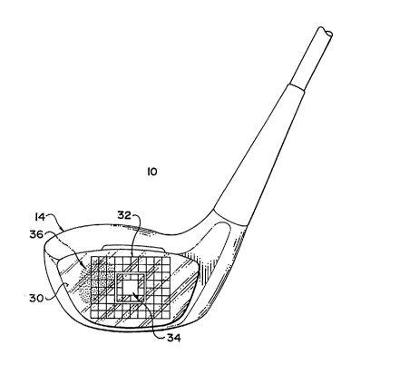
A golf club shown in Figure 1, in particular a
driver 10, has a shaft 12 to which is attached a club head
14 of wood, metal or composite material. Club head 14 has
a face 16 on which are cut slots or grooves 18 to impart
spin to the ball. Club head 14 also has a heel 20, toe 22
and sole 24.
The invention 30 is shown applied to the face 16
of the driver 10 in Figure 3 and the face 46 of an iron 40
in Figure 4. It has printed on its surface a grid such as
that shown as 32 to guide the golfer to the preferred
location 34, or sweet spot, for a particular club head.
Figure 5 illustrates the appearance of the invention on the
club face after striking a ball, with a darkened area 36
indicating the area of impact of the golf ball on the club
face. The golfer will then refer to written material or an
instructor to determine the necessary changes in stance,
grip, etc. to improve the impact location.
The structure of the invention is illustrated in
Figure 2. The top layer 31 consists of a textured clear
plastic, such as a high impact polystyrene or LEXANTM, of a
thickness on the order of 7 to 10 mil (.007 to .01 inches
or about 180 to 250 microns). This top layer 31 will have
grid 32 printed or etched onto its outer surface. Alterna-
tively grid 32 could be printed or etched on the lower
surface of layer 31, or the upper surface of layer 33. Top
layer 31 should be a high impact plastic so it is suffi-
ciently durable to withstand the mechanical abuse of
repeated striking by a golf ball. It is textured in order
to provide sufficient friction to impart spin to the golf
ball.


2093933
_ 4 _
Layer 31 is adhered to underlying layer 33 by a
contact cement. Layer 33 is a layer of high-hysteresis
(energy-absorbing) elastomeric foam, such as that sold
under the trade-mark ENSOLITE, of a thickness 1/16 in.- 1/8
in., depending on the club for which the indicator is
designed. A thicker foam layer of up to 3/32 in. will be
useful for putters. Applied to the upper surface of layer
33 is a backing layer of black paint of 1-2 mils in thick-
ness on top of which is applied a film of a temperature
sensitive liquid crystal, such as that manufactured and
sold under the trademark THERMAX by Thermographic Measure-
ments Ltd. of South Wirral, United Kingdom. This should be
a dual range temperature sensitive liquid crystal film
having a temperature response in the range l0 degrees C. to
70 degrees C. with the preferred range covering 15 degrees
C. to 45 degrees C. Such temperature sensitive liquid
crystal films change through a range of colours as a
function of temperature change. The layer of temperature
sensitive liquid crystal film may be applied to elastomer
layer 33 for example by screen printing.
A layer of pressure sensitive adhesive, having a
relatively low level of adherence, is applied to the lower
surface 35 of layer 33. A peel-off coated paper layer 37 is
provided over the pressure sensitive adhesive to cover the
adhesive until the device is attached to the club head.
To use the device, the paper layer 35 is peeled
off and the device 30 is stuck to face 16 of club l0, as
shown in Figure 3, by applying the pressure sensitive
adhesive surface of the device to the club face. The golfer
then strikes the golf ball with the desired stroke. a
portion of the energy of the impact of the golf ball on the
club face will be converted to thermal energy by the
energy-absorbing elastomer layer 33 and is conducted to the
liquid crystal film. The resulting temperature rise in the
temperature sensitive liquid crystal film is temporarily
displayed as a localized colour display, shown as 36 in


X093933
_ 5
Fig. 5. The display will disappear in 5 to 10 seconds as
the temperature differential disappears.
As will be apparent to those skilled in the art
in the light of the foregoing disclosure, many alterations
and modifications axe possible in the practice of this
invention without departing from the spirit or scope
thereof. Accordingly, the scope of the invention is to be '
construed in accordance with the substance defined by the
following claims.
1,.. ... ,
. . :
: . .. ..,.
.
.
,'a
'
~ '
'
'.
~
J


.
.
.'..
.
.
.
,
,
.. . ...'. ;. ..y, :: ..u
,::..:
.,;.. .,... '.~~'. n
.
.

~ ,.
:
.


~S ':. :;
. ; ,
. .
, :
. : . .
;.
, ., . .;:, ;:':
,~ :: ~ v:


~, ~ ,
~~ ..,
...,.
~"
~~
~
v
~
'.
'
~
~
~
~
~


~ ,
ri'. _
. ,,
..,
.:. ' :.
w , ' ',:
_
, ..
,,
:':: ,:'. , ,'.
,:
a -.
,
~; , ; - .


.
.
~ '
, ' ~
.
~


,,
:
.. .. . ..
~. . ,
. ~
.
~


.
:
.


.


:, ~ :..~
.
~ ..~.
:. ~ ~


. ..,
.
.
._,
.~: .,. ; .
,
:,.
'
~ '


,
,
.
. '
..
.
:: ,


' . .. :.' ' .. ' ' . : ; :. . : . : . : ., :: .. ; ~: ~.


Representative Drawing
A single figure which represents the drawing illustrating the invention.
Administrative Status

For a clearer understanding of the status of the application/patent presented on this page, the site Disclaimer , as well as the definitions for Patent , Administrative Status , Maintenance Fee  and Payment History  should be consulted.

Administrative Status

Title Date
Forecasted Issue Date 2000-05-16
(22) Filed 1993-06-11
(41) Open to Public Inspection 1994-12-12
Examination Requested 1997-05-30
(45) Issued 2000-05-16
Deemed Expired 2005-06-13

Abandonment History

There is no abandonment history.

Payment History

Fee Type Anniversary Year Due Date Amount Paid Paid Date
Application Fee $0.00 1993-06-11
Maintenance Fee - Application - New Act 2 1995-06-12 $50.00 1995-04-21
Maintenance Fee - Application - New Act 3 1996-06-11 $50.00 1996-04-17
Maintenance Fee - Application - New Act 4 1997-06-11 $50.00 1997-05-28
Request for Examination $200.00 1997-05-30
Maintenance Fee - Application - New Act 5 1998-06-11 $75.00 1998-05-06
Maintenance Fee - Application - New Act 6 1999-06-11 $75.00 1999-05-25
Registration of a document - section 124 $100.00 1999-08-05
Final Fee $150.00 2000-02-16
Maintenance Fee - Application - New Act 7 2000-06-12 $75.00 2000-02-16
Maintenance Fee - Patent - New Act 8 2001-06-11 $75.00 2001-05-16
Maintenance Fee - Patent - New Act 9 2002-06-11 $75.00 2002-05-27
Maintenance Fee - Patent - New Act 10 2003-06-11 $100.00 2003-05-21
Owners on Record

Note: Records showing the ownership history in alphabetical order.

Current Owners on Record
MULTIVISION HOLDINGS LTD.
Past Owners on Record
HOPE, NORMAN BRADBURN
Past Owners that do not appear in the "Owners on Record" listing will appear in other documentation within the application.
Documents

To view selected files, please enter reCAPTCHA code :


To view images, click a link in the Document Description column. To download the documents, select one or more checkboxes in the first column and then click the "Download Selected in PDF format (Zip Archive)" or the "Download Selected as Single PDF" button.

List of published and non-published patent-specific documents on the CPD .

If you have any difficulty accessing content, you can call the Client Service Centre at 1-866-997-1936 or send them an e-mail at CIPO Client Service Centre.


Document
Description 
Date
(yyyy-mm-dd) 
Number of pages   Size of Image (KB) 
Claims 1999-08-05 3 121
Cover Page 2000-04-19 1 32
Claims 1995-06-10 2 83
Description 1995-06-10 5 277
Representative Drawing 2000-04-19 1 9
Cover Page 1995-06-10 1 63
Abstract 1995-06-10 1 35
Drawings 1995-06-10 3 88
Representative Drawing 1998-08-10 1 13
Drawings 1999-08-05 3 61
Correspondence 2004-08-27 3 180
Assignment 1993-06-11 3 105
Prosecution-Amendment 1997-05-30 1 40
Prosecution-Amendment 1999-02-05 2 3
Prosecution-Amendment 1999-08-05 7 218
Assignment 1999-08-05 3 168
Correspondence 2000-02-16 1 36
Fees 1996-04-17 1 52
Fees 1995-04-21 1 46