Note: Descriptions are shown in the official language in which they were submitted.
92/07233 ~ PCr/US91/07511
METHOD AND APPARATUS FOR IHREE-DIMENSIONAL
NON-CONTACT SHAPE SENSING
Description
Technical Field
S This invention relates to optical mensuration devices in general, and in particular to an
improved method and apparatus ~or the optical mensuration of the surface shape of a three-
- dimensional object.
. .
Back~round Ar~
Numerous mensuration systems exist in the prior art for sensing the locations of surface
points on three-dimensional solid objects in relation to a predefined fi%ed reference frame or
coordinate system for input into an application system, such as a computer or other device for
measurement or analysis. For example, one type of mensuration system that can be used to
determine the location of a single point on the surface of an object includes the use of a narrow
projected beam of iight to illuminate a tiny area or spot on the surface of the object. A lens in
the system is positioned on an optical axis oblique to the axis of the projected beam and is used
to focus the reflected light from the illuminated spot onto a photoelectric sensor or onto a linear
array of sensors. Since the optical axis of the lens and sensor assembly in that type of system
is not coincident with the axis of the projected beam~ the position of the image of the illuminated
spot on the sensor will depend on the location of the particular illuminated surface point with
respect to the illuminating beam. Therefore, the location of the illuminated point with respect
to the predetermined reference frame can be determined by computing the distance of the
illuminated surface point from the origin of the light beam which, of course, is known.
~ Examples of such point illumination optical mensuration systems are found in the following U.S.
:` Patents: 4,660,970; 4,701,049; 4,705,395; 4,709,156; 4,733,969; 4,743,770; 4,753,528;
25 4,761,072; 4,764,016; 4,782,239; and 4,825,091.
:~ .
~' ' ,,
.
WO 92/07233 ~ J `~ PCI/US91/075
Of course, to determine the overall shape of an object, numerous individual surface
points, along with their respective locations, must be measured and recorded. Such optical
measurement of multiple surface points of an object is typically accomplished by mounting the
beam projector on a moveable scanning head capable of being moved from point-to-point with
S very high precision, such as the type cornmonly found on numerically controlled milling
machines. By precisely moving the beam projector mounted on the scanning head in a raster-like
scanning pattern, it is possible to measure the surface shape of the object being scanned by
measuring the individual locations of surface points individually illuminated by the point-like
scanning beam as it is scanned over the object's surface. Alternatively, the object itself can be
moved while the scanning head remains stationary. One disadvantage of this type of system is
that only one side of the object may be scanned at any one time, since other sides of the object
are hidden by the side being scanned. Scanning of these hidden sides can only be accomplished
by relocating either the scanning head or the object to expose the previously hidden surfaces to
the scarming beam. Obviously, such a relocation requires time and precision equipment to keep
track of the changed position of the scanning head, or the object in relation to the fixed reference
frame so that ~he new surface data will correspond to the previously obtained surface data.
Melical or three-dimensional scanning heads solve this problem by allowing the entire object to
be scanned at once. However, such helical systems are relatively expensive, since they require
complex mechanical apparatus to move the scanning head around the object in three-dimensions.
Regardless of the scanning method used, however, deep holes, overhangs, undercuts, and
surfaces nearly parallel to the axis of the scanning beam reduce the accuracy of the system, since
it is difficult to accurately measure these points, if they can even be illuminated by the scanning
bearn at all. For example, such systems cannot completely scan the inside, outside, and handle
details of a coffee cup without requiring the scanning apparatus to be relocated or the object to
be re-oriented so that the inside surfaces or other surfaces previously hidden from the scanning
beam can be illuminated by the beam. thus measured and recorded. As discussed earlier, such
) 92/07233 PCT/lJS91/07511
re-locations or re-orientations have the disadvantage of having to recalibrate the scanning
apparatus, or otherwise re-correlate the new surface points with respect to the original coordinate
system. Moreover, even if such relocations or reorientations are not required, such as in the
case of a helical scanning apparatus, there is still a severe loss of accuracy when scanning near
the top or bottom of a rounded object, unless the scanning head and detector are relocated to
better illuminate and detect such points. Furtherrnore, these types of systems are not very
portable or adaptable since they require high precision electro-mechanical or other apparatus to
accurately move the scanning heads (or the object) and define their positions in relation to the
predetermined reference frames. Therefore, all these prior art scanning systems will usually
require some type of relocation of the scanning apparatus or re-orientation of the object to
completely measure and record all of the surface details.
A variant of the above-described systems projects a thin beam of light in a single plane
which, of course, is incident as a line, as opposed to a point, on the surface of the object being
scanned. The intersection of this plane of light with the object's surface thus forms a brightly
illuminated contour line. A two-dimensional electronic video camera or similar device whose
optical axis is not coincident with the axis of the illuminating beam, detects the image of this
contour line. Again, since the optical axis of the camera is not coincident with the axis of the
illuminating light beam, it views the contour line from an oblique angle, thus allowing location
of the contour line to be precisely determined in relation to the known position of the beam
projector. Examples of inventions using this type of system are found in the following U.S.
patents: 4,821,200; 4,701,047; 4,705,401; 4,737,032; 4,745,290; 4,794,262; 4,821,200;
4,743,771; and 4,822,163.
To measure more than one contour line of an object, either the measuring apparatus or
the object is panned along (or rotated about) an axis through the object. While these line
scanning devices share similar drawbacks with the point scanning devices previously described,
they do operate much faster, gathering a larger number o f sample points during a given scanning
WO 92/07233 ~ PCr/US91/07
- 4
interval. Unfortunately, the accuracy of each surface sample point is limited by the relatively
low resolution of the two-dimensional charge coupled device (CCD) sensors found in most video
cameras, which is typically in the range of I part in 512. Even worse, these systems still suffer
the disadvantages of t'ne point scanning systems in that either tne scanning head or the object
S must be relocated or re-oriented to completely and accurately record all of the surface details of
an object.
Still other mensuration systems track the positions of specific points in three-dimensional
space by using small radiating emitters which move relative to fixed receiving sensors, or vice
versa. Such radiation emitters may take the form of sound, light, or nutating magnetic fields.
Another mensura~ion system uses a pair of video cameras plus a computer to calculate the
position of homologous points in the pair of stereographic video images. See, for example, U.S.
patents 4,836,778 and 4,829,373. The points tracked by this system may be passive reflectors
or active light sources. The latter simplifies finding and distinguishing the points.
Additional prior art relevant to this patent application are found in the following
references:
Burton~ R.P.; Sutherland, I. E.; "Twinkle Box-a three dimensional computer inputdevice", National Computer Conference, AFIPS Proceedings, v 43, 1974, p 513-520;
Fischer, P.; Mesqui, F.; Kaeser, F.; "stereometric measurement system for
quantification of object forms", SPIE Biostereometrics 602, 1985, p 52-57;
Fuchs, H.; Duran, J.; Johnson, B.; "Acquisition and Modeling of Human Body Form
Data", Proc. SPIE, v 166, 1978, p 94-102;
Macellari, V.; "A Computer Peripheral Remote Sensing Device for 3-Dimensional;
Monitoring of Human Motion", Med. & Biol. Eng. & Comput., 21 1983, p 311-318;
Mesqui, F.; Kaeser, F.; Fischer, P.; "real-time, noninvasive recording and 3-d display
of the functional movements of an arbitrary mandible point", SPIE Biostereometrics 602,
1985, p 77~84;
Yarnashita, Y.; Suzuki, N.; Oshima, M.; "Three Dimensional Stereometric Measurement
System Using Optical Scanners, Cylindrical Lenses, and Line Sensorsn, Proc. SPIE, v.
361, 1983, p. 67-73.
~ 92/07233 ~ l~ J ;~ ~ 3 9 Pcr/us9l/o75ll
s
In particular, the paper by Fuchs, et al, (1978) describes a basic method of tracking a
light source in three~imensional space. The method is based on using three or more one-
dimensional sensors, each consisting of a cylindrical lens and a linear array of photodetectors,
such as charge coupled devices (CCDs), to determine the location of the currently radiating
source.
Numerous other methods have been devised and patented for determining the position
of a point along a line, within a plane, or in three~imensional space. Devices employing these
methods include photographic camera rangefinders, tablet digitizers, coordinate measuring
machines, and surveying tools. Some exploit sound, magnetic fields, or mechanical apparatus
for mensuration, and there are other devices employing x-rays, nuclear magnetic resonance,
radar, sonar, and holography to sense the shapes of objects.
Unfortunately, each of the above mensuration systems has its own set of drawbacks,
which include high cost, poor accuracy, poor resolution, awkward or difFIcult use, limitations
on geometrical complexity, excessive numerical computation, or slow measurement speed.
Experience has shown that no single prior art system best suits all three-dimensional
measurement applications. For example, there is no existing mensuratiOD device that can
perform even straightforward anatomical measurements of a person without significant
drawbacks.
Thus, there remains a need fo~ a non-contact, three-dimensional optical mensuration
system which is capable of accurate, speedy, convenient, and inexpensive sensing of three-
dimensional geometric shapes or objects. Ideally, the scanning head of such an improved system
should be hand-held to allow the operator to easily move the scanning beam over some of the
more complex surface details of the object while dispensing with the need for the expensive,
cumbersome, and high precision scanning head positioning apparatus currently required. Such
a hand-held scanner must also provide the accuracy and precision associated with currently
WO 92/07233 ~ ~ ; v PCI /US91/075~?
available optical mensuration systems, that is, it must be able to accurately measure and precisely
locate the surface details of the object in relation to the predetermined reference frame.
Disclosure of Invention
Accordingly, it is an object of the present invention to provide an improved, non-contact,
S three-dimensional optical mensuration system capable of accurately sensing the surface shapes
of three-dimensional objects without the numerous drawbacks associated with the prior art
systems.
It is another object of this invention to provide an optical mensuration system that is
inexpensive, portable, and easy to use.
It is a further object of this invention to p}ovide a three~imensional optical mensuration
system which can quickly scan the surface of the object without the need for expensive,
complicated, and high precision mechanical positioning apparatus to position either the scanning
head or the object being scanned.
A still further object of this invention is to provide a portable, hand-held, and hand-
maneuverable scanner for the three-dimensional, non-contact shape-scanning and/or mensuration
of three-dimensional objects.
~dditional objects, advantages, and novel features of this invention shall be set forth in
part in the description that follows, and in part will become apparent to those skilled in the art
upon examination of the following or may be learned by the practice of the invention. The
objects and the advantages of the invention may be realized and attained by means of the
instrumentalities and in combinations particularly pointed out in the appended claims.
To achieve the foregoing and other objects and in accordance with the purposes of the
present invention, as embodied and broadly described herein, the apparatus for three-
dimensional, non-contact.shape sensing of this invention may comprise a hand held scanning
head wi-h a light source for proiecting a scanning light beam over the surface of the object being
`~'O 92/07233 PCT/US91/07511
2 ~ J I O ~ ~
scanned. Two spot detectors mounted on the hand-held scanning head are operative to detect the
position of the illuminated spot on the surface of the object in relation to the scanning head.
Three pilot light detectors, the positions of which are known with respect to a predetermined
coordinate system, detect the positions of the three pilot light emitters positioned in spacc:: -apart
relation on the scanning head as the pilot light emitters are strobed in sequence. A coordi~ate
computer connected to the scanning head and to the pilot light detectors receives data from the
spot detectors and calculates the position of the illuminated spot with respect to the scanning
head. The coordinate computer then calculates the various positions and orientations of the
scanning head in relation to the predetermined coordinate system on a real time basis from the
data received from the pilot light detectors. Finally, the coordinate computer calculates the
position of the illuminated spot in relation to the predetermined coordinate system by correlating
the position of the illuminated spot in relation to the scanning head with the position of the
scanning head in relation to the predetermined coordinate system.
The method of this invention includes the steps of sweeping a scanning beam projected
from the hand held scanning head over the surface of the object being scanned to illuminate a
spot on the surface of the object, detecting the position of the illuminated spot with respect to
the scanning head~ detecting the position of the scanning head in relation to a predetermined
coordinate system! and computing the position of the illuminated spot in relation to the
p~edetermined coordinate system by correlating the position of the illuminated spot in relation
to the scanning head with the position of the scanning head in relation to the predetermined
coordinate system.
Brief DescriDtion of the Drawings
The accompanying drawings, which are incorporated herein and form a part of the
specification illustrate preferred embodiments of the present invention, and together with the
descrintion, serve to explain the principles of the invention.
. .
WO 92/07233 PCI/US91/07
. ~ , .,
1n the drawings:
Figure 1 is a block diagram of the optical mensuration apparatus of the present invention
showing the major components;
Figure 2 is a perspective view of the hand held scanning head of the present invention,
showing how it can be positioned to direct the scanning beam onto the surface of the object being
scanned;
Figure 3 is a plan view of the scanning head of the present invention with the top surface
broken away to more clearly show the arrangement of the optical projecting apparatus and the
spot detectors;
Figure 4 is a schematic perspective representation of one of the one-dirnensiorlal
photodetectors of the present invention;
Figure 5 is a schematic block diagram of the optical mensuration apparatus of the present
invention showing in detail the functions and operations of the control unit and coordinate
computer; and
Figure 6 is a graph of signal strength vs. Iocation on the detector surface for a typical
light detector used by the optical mensuration apparatus of the present invention.
Best Mode fQr Carrvin~ OIIt the Invention
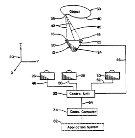
The optical mensuration apparatus 10 of the present invention is shown schematically in
Figure I and comprises a hand-held or moveable scanning head 12 housing light beam projecting
apparatus 14 (not shown in Figure 1, but shown in Figure 3), two one-dimensional spot sensors
or detectors 16, 18, and three pilot light emitters 20, 22, and 24. Three remotely located, one-
dimensional pilot light sensors 26, 28, and 30 are mounted in fixed, spaced-apart relation to each
other and are located at known positions-with respect to a predetermined reference coordinate
system or frame 80. These three pilot sensors 26, 28, and 30 sense the light projected by the
individual pilot light emitters 20~ 22, and 24 and generate electrical output signals from which
.
,;,, " ,
~/O 92/07233 .~ u, ~ ) PCrtUS91/07511
, ...
are derived the location of the scanning head 12 with respect to the fixed coordinate system 80.
A control unit 32 connected to the moveable scanning head 12 via data line 46 and connected
to the remotely located sensors 26, 28, and 30 via data lines 48, 50, and 52, respectively,
synchronizes the time multiplexing of the three pilot emitters 20, 22, and 24, controls the
operation of the beam projecting apparatus 14, and receives data from the two spot sensors 16,
18 on scanning head 12, as will be completely described below. A coordinate computer 34,
coMected to control unit 32 by data line 54 calculates the three~imensional spatial coordinates
of the illuminated spot 36 in relation to the predetermined coordinate reference frame 80, which
position information can then be used by an application system 82.
ln operation, the light bea~,n projecting apparatus 14 housed in the hand held scanner
head 12 directs a narrow beam of light or scanning beam 42 onto the surface 40 of object 38 to
illuminate a small portion or spot 36 on the surface 40. Reflected light 43 from illuminated spot
36 is detected by the two one-dimensional spot sensors or detectors 16, 18 mounted on scanner
head 12. These sensors 16, 18 sense the location of the illuminated spot 36 with respect to the
position of the moveable scanner 12 by measuring the relative angular parallax of the reflected
light 43 from illuminated spot 36. Ne~tt, the spatial position and orientation of the moveable
scanner head 12 at thst same instant are determined by messuring the locations of the three time
multiplexed pilot light emitters 20, 22, and 24 relative to the known positions of the pilot light
sensors 26, 28, and 30. Finally, the parallax data from each of the sensors 16, 18, 26, 28, and
30 are ultimately fed to the coordinate computer 34, which determines the position of the
illuminated spot 36 with respect to the predetermined reference frame by correlating the position
of the illuminated spot 36 in relation to the scanner head 12 with the position of the scanner 12
in relation to the fixed pilot light sensors 26, 28, and 30, which are positioned in relation to the
predetermined reference frame 80 at precisely predetermined locations at conveniently spaced
distances from each other and from the object 38 and the hand-held scanner 12. If the computer
can make these location or position calculations very fast, the operation can he performed over
WO 92/07233 ~ ~;, ` `' PCr/US91/075
and over again in sequence as the scanner head 12 moves in relation to the object, thus resulting
in effectively real time mensuration of the object as the scanner head 12 moves.By using this two-stage measurement system, i.e., first measuring the location of the
illuminated spot 36 in relation to the scanning head 12 at a particular instant in time, and then
determining the posi~ion of the scanning head 12 in relation to the predeterrnined reference frame
at that same instant in time, the optical mensuration apparatus 10 of the present invention
dispenses with the need for high precision head positioning apparatus and the complex and
expensive mechanical structure typically associated therewith. Further, the hand-held scanner
12 is easily manipulated by the operator to direct the scanning bearn 42 over complex, interior,
or blind surface details, which would otherwise be difficult to scan, thus speeding the scanning
operation.
The details of the optical mensuration apparatus 10 of the present invention are best
understood by referring to Figures 2, 3, and 4 simultaneously. Essenfially, the hand-held
scanner head 12 houses the light beam projecting apparatus 14 (Figure 3), the two one-
dimensional spot sensors or detectors 16, 18, and the three pilot light emitters 20, 22, and 24.
A handle 44 allows the scanner head 12 to be easily manipulated by the operator to guide the
scanning beasn 42 over the various shapes and hidden contours of the surface 40 of object 38.
In the preferred embodiment, the light beam projecting apparatus comprises a helium-
neon (He-Ne) laser 56 to generate collimated scanning beam 42. Of course, other devices could
be used to produce the spot-like scanning beam, as would be readily apparent to persons having
ordinary skill in the art. For example, laser 56 could be replaced by a light emitting diode
t~LED) and associated collimating lens. Other sources and lens combinations are possible so long
as the apparatus is capable of projecting a small, well defined beam of light on the surface of the
object. A planar mirror 58, which could be optionally pivotally mounted as shown in Figure 3,
directs beam 42 to a rotating many-faceted mirror 60, which directs, or scans beam 42 over the
surface 40 in a single plane relative to the scanner 12 ti.e.. the plane of the paper in Figure 3).
';
`~'O 92/07~33 ~ 1Ji 9 ~ ~ 3 ~ PCI/US91/07511
11
Of course, the number of sides of the rotating, many-faceted mirror 60 determines the angle
through which scanning beam 42 sweeps. For example, the pentagonal mirror shown in Figure
3 will sweep the beam through a 144-degree angle. More sides will sweep the beam through
;: smaller angles. Moreover, other scanning paths are possible by using irregularly shaped mirrors
or multiple rotating mirrors, and the present invention should not be regarded as limited by the
par~icular scanning apparatus shown and described herein.
While the rotating mirror 60 can be rotated in either direction with equal effectiveness,
the rotating mirror 60 in the preferred embodiment 10 is rotated in the direction indicated by
arrow 62 by a simple, unsynchronized motor (not shown). As mentioned above, planar mirror
58 may be optionally pivotally mounted such that it can be swung out of the beam path to
position 58' (shown in broken lines in Figure 3) to inhibit the scanning action of the beam 42.
With the mirror at position 58' the beam 42 will exit straight out aperture 64 in scanner 12
which can then be used as a point-type scanner or as a non-contact pointer for identifying some
single point of interest on the surface 40 of object 38.
The details of the one-dimensional spot detectors 16, 18 are best understood by referring
to Figure 4. Actually, all of the one-dimensional sensors 16, 18, 26, 28, and 30 used in the
preterred embodiment 10 of the present invention are identical to the one-dimensional spot
detector 16 in every respect. Therefore, for the purpose of giving a detailed description of this
embodiment, only the sensor 16 is shown and described in detail since the remaining sensors 18,
26, 28, and 30 have identical features.
Referring now to Figure 4, the one-dimensional sensor 16 comprises a cylindrical lens
66 that has a longitudinal axis 74 which is orthogonal to the optical axis 76 of the sensor 16.
A linear photodetector 68, such as a charge coupled device (CCD) with several thousand
elements, or a similar device capable of linear light detection with an elongated aperture`78 is
positioned in such a manner that optical axis 76 passes through aperture 78 and such that the
long axis of aperture 78 is orthogonal to the plane containing the longitudinal axis 74 of lens 66.
Wo 92/07~33 ~ ' PCr/US91/075
12
The incident light beam 43 reflected from illuminated spot 36 is then focused by the cylindrical
lens 66 into a real image line 72 on the surface 70 of linear photodetector 68, which is a
characteristic of this type of lens.
The CCD detector 68 then generates a signal, such as the one shown in Figure 6, that
is related to the position of real image line 72 on tbe surface 70 of photodetector 687 thus
characterizing the location of the image itself. That is, those elements of the detector 68
illuminated by the real image line 72 will generate a strong signal, while those not illuminated
will generate a wealc signal. Thus, a graph of signal strength vs. Iocation on the surface of the
CCD will resemble the signal peak curve 100 shown in Figure 6. Note that the "zero" signal
level 102 is never quite zero due to the effects of background light and other imperfections in
the sensor. In any event, since the image of illuminated SpOt 36 is focused into line 72, only the
horizontal displacement of spot 36 from optical axis 76 is measured by detector 68, hence the
designation "one-dimensional detector."
Thus, a single one-dimensional detector 16 can only locate the plane on which spot 36
tS particular beam lies, but detector 16 cannot, by itself, determine the unique location or position
in space on which point 36 is located. To precisely locate the location in space of point 36
would require three such detectors positioned in spaced-apart relation to each other, since the
intersection of three planes defines a point. However, if the plane containing the aperture 78 of
detector 16 is in the same plane as the scanning beam 42, only two detectors are rsquired to
uniquely locate ths position of spot 36. Therefore, in the preferred embodiment 10 of the
present invention~ the apertures 78 of the respective photodetectors 16, 18, lie in the same plane
as the scanning beam 42, thereby allowing the exact point in space of illuminated spot 36 to be
determined with only two detectors 16, 18.
The three pilot light emitters 20, 22, and 24 (Figures 1-3) can be high intensity light
emitting diodes (LEDs), which are preferably time multiplexed or strobed by control unit 32 in
a predetermined manner such that only one pilot light LED is "on" or emitting light at any one
`"O 92/07233 s PCr/US91/07511
Q "~
13
time. The light emitted from any one of these emitters 20, 22, and 24 is detected by each of the
three pilot light detectors 26, 28, and 30, which then determine the position of that particular
emitter in relation to the known positions of the detectors 26, 28, and 30 at the instant in time
that it is strobed or illuminated. To locate the position of a particular illuminated one of emitters
20, 22, 24, the pilot light detectors 26, 28, and 30 are mounted so that their optical axes are not
collinear. In the preferred embodiment, two pilot light detectors, such as detectors 26, 30 in
Figure 1, are situated such that their respective axes 74 (Figure 4) are in parallel spaced-apart
relation, with the third detector 28 situated between the first two, but with its axis 74
perpendicular to the first two. As described above, each of the detectors 26, 28, and 30 then
determine~, a unique plane in which the given pilot emitter lies, the intersection of which defines
the exact location of that illuminated emitter.
While this process of detecting the position of a given illuminated pilot emitter 20, 22,
24 can locate the exact position of the illuminated emitter, it cannot determine the particular
orientation of the entire scanner head 12 in three-dimensions. To do so requires the detection
of the locations of at least three spaced-apart emitters whose orientations with respect to one
another are known. Therefore? the optical mensuration system 10 of the present invention
determines the orientation of the scanning head 12 in three-dimensional space by using the three
(3) pilot emitters 20, 22, and 24, whose relative positions on the scanning head 12 are fixed and
known. Consequently, when each of the emitters 20, 22, and 24 are rapidly turned on in
sequence, the sensors 26, 28, and 30 can detect the exact position of each emitter in turn, thus
determine the exact location and orientation of the scanning head 12. Since only one of the pilot
light emitters 20, 22, 24 is on at any one time, the detectors 26, 28, 30 locate the position of that
particular illuminated pilot light only. If the strobe rate, that is, the frequency at which the
emitters 20, 22, 24 are turned on and off in sequence, is fast enough, the detectors 26, 28, and
30 can, for all practical purposes, determine the position and orientation of the scanning head
t2 at anv instant in time.
WO 92/07233 ~9 PCr/US91/07S~
J 14
Note that the detectors 26, 28, 30, need only distinguish which of the pilot light emitters
20, 22, 24 is "on" or illuminated at any one time. In the preferred embodiment 10 of the present
invention, this function is accomplished by strobing or illuminating each of the emitters 20, 22,
24 in sequence. However, other methods could be used to allow the detectors 26, 28, 30 to
distinguish the respective pilot light emitters 20, 22, 24 from one another. For example,
different colors of light could be used in conjunction with detectors capable of distinguishing
those particular colors or wavelengths of light. Alternatively, the resp~ctive pilot light emitters
20, 22, 24 could be modulated with a unique "tone" for each emitter. The control unit 32 or
coordinate computer 34 could then be programmed to demodulate the tone, thus determine to
which particulat emitter 20, 22, or 24 the position signal belongs. Numerous other methods of
distinguishing the pilot light emitters 20, 22, and 24 are possible and would be readily apparent
to petsons having ordinary skill in the art. Therefore, the present invention should not be
tegarded as limited to the particular strobing method shown and described herein.
The details of the structure and operation of the control unit 32 are best seen in Figure
S. Specifically, control unit 32 supplies power to the light beam ptojecting apparatus or source
14, the beam spot sensors 16, 18, the pilot light emitters or sources 20, 22, and 24, and the pilot
light sensors 26, 28, and 30. The control and synchtonization unit 84 and light source sequencer
86 time multiplexes or strobes the beam ptojecting apparatus 14 and the pilot lights 20, 22, and
24 individually, as described above, so that the position and orientation of the scanning head 12
can be determined from the signals received from pilot light sensors 26, 28 and 30. The angular
data signals received from the pilot light sensors 26, 28, and 30 and from the spot sensors 16,
18, are convetted by analog to digital converter 88. Actually, five analog to digital converters
are used, as shown in Figute 5, but only one is labeled and described herein for brevity, since
the other four analog to digital converters are identical and are used to convert the signals from
sensors 28 and 30 and 16 and 18, respectively.
'
...
: ' ' ~ . -
s ') 92/07233 PCr/ US91 /07511
3 ~
The control and synchronization unlt ~4 also controls five switches, of which switch 90
is typical, which store all digital data received from the sensors 26, 28, and 30 and 16 and 18
when the pilot light emitters and scanning beam 42 are "off," and stores these data in background
TnemOry 92. Then, when the pilot light sources and scanning beam are illuminated in sequence
by light source sequencer 86, the control and synchronization unit 84 changes the state of switch
90, which then redirects the data from the five sensors to the subtraction unit 94. Subtraction
unit 94 subtracts the "background" data from the illuminated data, thus resulting in a signal
relatively free from background noise signal 102 (Figure 6), since it has been subtracted from
the signal.
Referring now to Figures 4 and 6 in conjunction with Figure 5, the first-last over-
threshold unit 96 computes the location of the real image line 72 on the CCD sensor 68 (Figure
4) by measuring the locations of the edges 104, 106 of the signal blip 100 (Figure 6) generated
by the CCD sensor based on a predetermined threshold signal level. The first-last over-threshold
unit 96 then averages the distance between the two edges to find the center of the signal peak,
which is often dipped, as shown in Figure 6. This particular method of determining the center
of the signal peak is well known in the art and will not be described in further detail. Moreover,
numerous other methods of determining the location of the signal peak are known in the art, and
would be obvious to those having ordinary skill in the art. The particular method used would
depend on the signal characteristics of the particular light sensor used, as well as the
characteristics of the lens system used to focus the light onto the surface of the detector, as well
as other parameters. Those practicing this invention with the various alternates described herein
would have no trouble selecting a signal detection algorithm best suited to the particular
characteristics of the sensors.
Finally, control unit 32 (Figure 5) transmits the position data to the coordinate computer
34. That is, when the coordinate computer 34 is ready to compute the current location of the
illuminated snot 36 on the object~ the latest angular data from all sensots are provided for
W092/07233 ? ~ i ' PCI/USg1/075
16
analyzation. If the spot sensors 16, 18, or the pilot light sensors 26, 28, and 30, generate data
faster than the control unit 32 can process them, the angular data are simply discarded.
The details of the coordinate computer 34 are also best seen in Figure 5. Essentially,
the coordinate computer 34 calculates one-dimensional positions for each light source based on
S the location of the signal peak from each respective sensor. These one-dimensional positions are
then used to calculate the three-dimensional spatial coordinates for the illuminated spot 36 and
for the scanning head 12 in relation to the predetermined coordinate system 80, by coordinate
transformation methods which are well-known in the art. The output from the coordinate
computer 34 can be in any form desired by the operator or required by the application system
80, such as XYZ coordinate triples based upon some predeterrnined stationary rectangular
coordinate system.
The operation of the optical mensuration apparatus of the present invention is as follows.
Upon illumination of a spot 36 on the surface 40 of object 38, the two spot sensors 16, 18 inside
the scanner head 12 sense the angular position of the illuminated spot 36 at a given instant in
time. The signals from these spot sensors 16, 18, are directed to the control unit 32 via data line
46. Next, the pilot light detectors 26, 28, and 30 are used to sense the individual positions of
the three pilot light emitters 20, 22, 24 in sequence as described above. That is, each pilot light
detector 26, 28, 30, measures the angle of rays from each of three pilot light emitters 20, 22,
24, mounted on the scanner 12. The angular data from each of these sensors 26, 28, and 30 are
also directed to control unit 32 via data lines 48, 50, and ~2.
As described above, the control unit 32 converts the angular data from each of the
sensors 16, 18, 26, 28, and 30, which is in analog form, to digital data and tags these data with
information identifying their respective sources. These converted digital data are then processed
by removing the background noise and by using known signal detection methods to determine
the center of tne signal peak, thus the location of the image line 72 on the detector 68. These
position locations of the centers of the respective signal peaks from each detector 16, 18, 26. 28,
~: .
~? 92/07233 ~ Pcr/Us91/075~1
, . . .
and 30 are then directed to coordinate computer 34 via data line 54, which then computes the
current location of the illuminated spot 36 with respect to the predetermined coordinate system
80. Sequential calculations and beam spot position determination can be made as fast as the
computer can do so, thus many such points on the surface of the object can be determined as
they are scanned almost on a real time basis. These position data can be stored in comp~i er
memory, recalled, and correlated together to produce an image of the object in precise
reproduction detail, or various points or other features on the object can be mensurated or used
in any manner desired.
This completes the detailed description of the method and apparatus of the optical
mensuration apparatus 10 of tbe present invention. While some of the obvious and numerous
modifications and equivalents have been described herein, still other modifications and changes
will readily occur to those skilled in the art. For instance, the preferred embodiment uses visible
light since human operators can readily observe if the light sources are operative or whether they
are causing troublesome reflections. Clearly, other wavelengths of electromagnetic radiation
could be used without departing from the spirit and scope of this invention. Further, it would
be possible to include circuitry in the detectors which would subtract out the ambient light, thus
improve the detection efficiency of the invention. Other modifications to the detector optics and
lenses are possible which would alter the image characteristics on the detectors. For example,
cylindrical lenses could be used which have been longitudinally cuNed along an arc with a radius
equal to the focal length of the lens. Similarly, the surfaces of the photodetectors could also be
cuNed, thus allowing the images of distant light sources to remain in sharp focus regardless of
their positions. Various measurements of the detector outputs are also possible. For example,
the angle of peak intensity, the intensity-weighted average, or the average of the minimum and
maximum angles where the intensity is over some predetermined threshold value could be used.
Finally, numerous enhancements of the digital data are possible by programming the coordinate
.
WO 92/0~233 ~ , PCI/US91/07
18
computer to make the appropriate enhancements, as would be obvious to those persons having
ordinary skill in the art.
The foregoing is considered illustrative only of the principles of ~he invention. Further,
since numerous modifications and changes will readily occur to those skilled in the art, it is not
S desired to limit the invention to the exact construction and operation shown and described, and
accordingly, all suitable modifications and equivalents may be resorted to as falling within the
scope of the invention as defined by the claims which follow.