Language selection

Search

Patent 2094048 Summary

Third-party information liability

Some of the information on this Web page has been provided by external sources. The Government of Canada is not responsible for the accuracy, reliability or currency of the information supplied by external sources. Users wishing to rely upon this information should consult directly with the source of the information. Content provided by external sources is not subject to official languages, privacy and accessibility requirements.

Claims and Abstract availability

Any discrepancies in the text and image of the Claims and Abstract are due to differing posting times. Text of the Claims and Abstract are posted:

  • At the time the application is open to public inspection;
  • At the time of issue of the patent (grant).
(12) Patent: (11) CA 2094048
(54) English Title: BLANK FIRING ATTACHMENT
(54) French Title: DISPOSITIF DE TIR A BLANC
Status: Expired
Bibliographic Data
(51) International Patent Classification (IPC):
  • F42B 8/04 (2006.01)
  • F41A 21/26 (2006.01)
(72) Inventors :
  • COMPTON, DAVID W. (Canada)
  • HORTOBAGYI, THOMAS (Canada)
(73) Owners :
  • HER MAJESTY THE QUEEN, IN RIGHT OF CANADA, AS REPRESENTED BY THE MINISTE R OF NATIONAL DEFENCE (Canada)
(71) Applicants :
  • COMPTON, DAVID W. (Canada)
  • HORTOBAGYI, THOMAS (Canada)
(74) Agent: CASSAN MACLEAN
(74) Associate agent:
(45) Issued: 2004-04-27
(22) Filed Date: 1993-04-15
(41) Open to Public Inspection: 1994-10-16
Examination requested: 2000-04-11
Availability of licence: N/A
(25) Language of filing: English

Patent Cooperation Treaty (PCT): No

(30) Application Priority Data: None

Abstracts

English Abstract


The invention is a blank firing attachment for use
on a gas operated automatic rifle or light machine gun. The
device restricts the exit of gases from the rifle barrel when a
blank cartridge is fired, thus retaining sufficient gas pressure
in the barrel to actuate the rifle's automatic firing mechanism
and permit blank cartridges to be fired automatically or semi-automatic.
The device has a body adapted to be attached to
the muzzle compensator of a rifle and a stem having an axial
cavity. The stem is adapted to seal against the inner bore of
the compensator.


Claims

Note: Claims are shown in the official language in which they were submitted.


THE EMBODIMENTS OF THE PRESENT INVENTION IN WHICH AN EXCLUSIVE
PROPERTY OR PRIVILEGE IS CLAIMED ARE DEFINED AS FOLLOWS:

1. A blank firing attachment for use on a gas operated automatic rifle or
light machine gun of
the type having a barrel, a muzzle compensator affixed to the forward end of
the barrel and an
automatic firing mechanism actuated by gas pressure in the barrel caused by
firing a bullet,
comprising:
a. a body adapted to be attached to said muzzle compensator, said body being
generally
half cylindrical and having a flange at its forward end for engagement with a
groove
in said muzzle compensator;
b. a stem attached to said body, said stem having a forward end, a rear end,
an axial
cavity open at said forward end and a gas exhaust port leading from said
cavity, said
forward end of said stem having a tapered sealing surface and being insertable
into
the forward end of said muzzle compensator, whereby said tapered sealing
surface
seals against a mating tapered internal wall of said muzzle compensator to
form a
partially sealed chamber open through said gas exhaust port, whereby
sufficient gas
pressure is retained in said barrel after a blank round is fired to actuate
said automatic
firing mechanism of said rifle.

2. A blank firing attachment in accordance with claim 1, wherein said stem is
attached to said
body by inter-engaging screw threads on the exterior of said stem and the
interior of a bore in said
body.


3. A blank firing attachment in accordance with claim 1, further comprising a
ring attached to
said rear end of said stem for threadably turning said stem.

4. A blank firing attachment in accordance with claim 1, wherein said stem is
made of ASTM
A331 Grade 4140 cold finished steel.

Description

Note: Descriptions are shown in the official language in which they were submitted.


2004048
BLANK FIRING ATTALHMENT
Field of the Invention
The invention is a device for use on rifles or light
machine guns to enable them to fire automatically or semi-
automatically when they are used for firing blank cartridges.
~ackaround of the Invention
Some types of gas operated rifles or light machine guns
have an automatic firing mechanism which is actuated by the
pressure waves created by an ignited cartridge and bullet as the
bullet travels down the rifled barrel. The automatic firing
mechanism loads the next cartridge to be fired into the breach
of the rifle. In such rifles or light machine guns, the pressure
waves travel through a gas system connecting the barrel and the
loading mechanism. However, when a blank cartridge is fired
there is no bullet to create the proper pressure-time
relationship needed by the rifle or light machine gun in order
to function in an automatic or semi-automatic mode. If the
exploding gases from the blank cartridge are permitted to exit
the muzzle of the barrel without proper restriction, the
pressure-time relationship in the barrel and gas system will not
match the energy requirements needed to make the automatic firing
mechanism function. The rifle or light machine gun will
accordingly not operate automatically when firing blank
cartridges. To create the required pressure wave and achieve
automatic firing, it is necessary to restrict the escape of gases
from the muzzle of the rifle or light machine gun.
The invention is a device, referred to as a blank
1


2094048
firing attachment, which attaches to automatic or semi-automatic
rifles and light machine guns to restrict the escape of the gases
produced by firing a blank cartridge, thus actuating the
automatic firing mechanism and permitting the automatic or semi-
automatic firing of blank cartridges. The invention will allow
for proper function of the automatic firing mechanisms of: the
M16 family of weapons which includes but is not limited to rifles
designated as M16, M16A1, M16A2, AR15, AR15A2, C7, C7A1, C8
carbines and other versions; the MINIMI family of weapons which
includes but is not limited to light machine guns designated C9,
C9A1 and M249 and other versions: and any alternative
configuration of weapon that could be used to practice the
present invention.
According to an embodiment of the invention, there is
provided a blank firing attachment for use on an automatic or
semi-automatic rifle or light machine gun of the type having a
barrel, a muzzle compensator or flash eliminator affixed to the
forward end of the barrel and an automatic firing mechanism
actuated by gas pressure in the barrel caused by firing a live
bullet. The attachment comprises: (a) a body adapted to be
attached to the muzzle compensator: and (b) a stem attached to
the body, the stem having a forward end, a rear end, an axial
cavity open at the forward and and a gas exhaust port leading
from the cavity to the outside. The stem is insertable into the
forward end of the muzzle compensator to form a partially sealed
chamber open through the gas exhaust port, whereby sufficient gas
pressure is retained in the barrel after a blank round is fired
to actuate the automatic firing mechanism.
2


2004048
The blank firing attachment .attaches quickly to a rifle
or light machine gun without tools, without the need to modify
the rifle and without damage to the rifle or muzzle compensator
or flash eliminator. The attachment can be quickly removed
without tools to return the rifle or light machine gun to normal
firing.
grief Description of the Drawings
In drawings which illustrate the preferred embodiment
of the invention:
Fig. 1 is an elevation view of the blank firing
attachment;
Fig. 2 is an elevation view of the blank firing
attachment rotated axially 90° from the view of Fig. 1: and
Fig. 3 is a view partially in section of the blank
firing attachment mounted on the muzzle compensator of an
automatic rifle.
stained Description of the Preferred Embodiment
The preferred embodiment of the blank firing attachment
is for use on type C7 and C8 M-16 rifles and on type C9 rifles.
Referring to Figures 1 and 2, the blank firing attachment
comprises a body 2, stem 4 and split ring 6. Stem 4 has a
threaded portion 10 which engages with threaded bore 12 (shown
in Fig. 3) of body 2, permitting stem 4 to be advanced and
retracted through bore 12 by rotating stem 4. Split ring 6 is
affixed through orifice 16 in the rear end 14 of stem 2 to
provide a convenient handgrip to enable the stem 4 to be rotated.
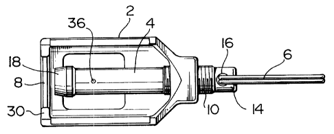
Referring to Figure 3, stem 4 has an axial cavity 34
open at the forward end 18 of the stem. Gas exhaust port 36 in
3


2094048
the side of stem 4 provides an opening from cavity 34 to the
outside.
Body 2 is in the general form of a half cylinder, open
on one side and configured to permit convenient attachment to a
muzzle compensator. Body 2 has flange 30 at its forward end to
engage with a muzzle compensator as described below. A muzzle
compensator, also referred to in the art as a flash eliminator,
is a known device affixed to the muzzle of an automatic rifle to
control the recoil and flashing that result from firing live
bullets. In this specification and the appended claims, the term
muzzle compensator is used for convenience, and includes flash
eliminators. As shown in Fig. 3, muzzle compensator 20 is
affixed to the muzzle end of gun barrel 22, with muzzle 24
opening into axial passage 26 of muzzle compensator 20. When the
blank firing attachment is not mounted on the muzzle compensator,
axial passage 26 is open to the outside to permit the exit of
bullets from the rifle. The blank firing attachment is attached
to muzzle compensator 20 by the steps of partially retracting
stem 4 through bore 12 in body 2, engaging flange 30 of body 2
in groove 28 of compensator 20 and then advancing stem 4 through
bore 12 until walls 40 of forward end 18 of stem 4 abut inner
wall 32 of muzzle compensator 20. Inner wall 32 and walls 40 of
stem 4 have matching 20° tapers which engage to form a seal.
With the blank firing attachment in position on the muzzle
compensator, a chamber is formed at the end of muzzle 24
comprising (a) the portion of axial passage 26 between muzzle
24 and stem 4 and (b) cavity 34 in stem 4. This limits the exit
of gases from the muzzle of the weapon, permitting only the
4


20~~048
restricted release of gases to the outside through gas exhaust
port 36.
In operation, when a blanl~ cartridge is fired, the
resulting gas pressure is confined by the blank firing attachment
sufficiently that the pressure in the barrel actuates the
automatic firing mechanism (not illustrated) of the rifle or
light machine gun, thus permitting the automatic firing of blank
cartridges. Gas exhaust orifice 36 permits gas to vent from the
barrel, providing the firing sound desired when firing blank
cartridges.
In the preferred embodiment, stem 4 is 2.30 inches
long, cavity 34 is .875 inches deep and .140~ .003 inches in
diameter: gas exhaust port 36 is .0551 .002 inches in diameter
and .500 inches from the forward end of stem 4. Stem 4 is
constructed of ASTM A331 Grade 4140 cold finished steel, in order
to withstand the corrosive gases, and consequent erosion of
metal, produced when firing blanks.
The preferred embodiment of the invention has been
described above, but it will be apparent to a reader skilled in
the art that alternative configurations could be used to practice
the present invention. All such configurations are within the
scope of the invention, which is defined in the appended claims.

Representative Drawing
A single figure which represents the drawing illustrating the invention.
Administrative Status

For a clearer understanding of the status of the application/patent presented on this page, the site Disclaimer , as well as the definitions for Patent , Administrative Status , Maintenance Fee  and Payment History  should be consulted.

Administrative Status

Title Date
Forecasted Issue Date 2004-04-27
(22) Filed 1993-04-15
(41) Open to Public Inspection 1994-10-16
Examination Requested 2000-04-11
(45) Issued 2004-04-27
Expired 2013-04-15

Abandonment History

Abandonment Date Reason Reinstatement Date
1999-04-15 FAILURE TO PAY APPLICATION MAINTENANCE FEE 1999-07-30

Payment History

Fee Type Anniversary Year Due Date Amount Paid Paid Date
Application Fee $0.00 1993-04-15
Registration of a document - section 124 $0.00 1994-10-21
Reinstatement: Failure to Pay Application Maintenance Fees $200.00 1995-10-13
Maintenance Fee - Application - New Act 2 1995-04-17 $100.00 1995-10-13
Maintenance Fee - Application - New Act 3 1996-04-15 $100.00 1996-04-10
Maintenance Fee - Application - New Act 4 1997-04-15 $100.00 1997-04-14
Maintenance Fee - Application - New Act 5 1998-04-15 $150.00 1997-12-15
Reinstatement: Failure to Pay Application Maintenance Fees $200.00 1999-07-30
Maintenance Fee - Application - New Act 6 1999-04-15 $150.00 1999-07-30
Maintenance Fee - Application - New Act 7 2000-04-17 $150.00 2000-03-14
Request for Examination $400.00 2000-04-11
Maintenance Fee - Application - New Act 8 2001-04-17 $150.00 2001-04-10
Maintenance Fee - Application - New Act 9 2002-04-15 $150.00 2002-01-22
Maintenance Fee - Application - New Act 10 2003-04-15 $200.00 2003-03-11
Maintenance Fee - Application - New Act 11 2004-04-15 $250.00 2004-01-30
Final Fee $300.00 2004-02-12
Maintenance Fee - Patent - New Act 12 2005-04-15 $250.00 2005-02-03
Maintenance Fee - Patent - New Act 13 2006-04-17 $250.00 2006-01-19
Maintenance Fee - Patent - New Act 14 2007-04-16 $250.00 2007-04-02
Maintenance Fee - Patent - New Act 15 2008-04-15 $450.00 2008-03-07
Maintenance Fee - Patent - New Act 16 2009-04-15 $450.00 2009-04-09
Maintenance Fee - Patent - New Act 17 2010-04-15 $450.00 2010-04-12
Maintenance Fee - Patent - New Act 18 2011-04-15 $450.00 2011-04-11
Maintenance Fee - Patent - New Act 19 2012-04-16 $450.00 2012-03-22
Owners on Record

Note: Records showing the ownership history in alphabetical order.

Current Owners on Record
HER MAJESTY THE QUEEN, IN RIGHT OF CANADA, AS REPRESENTED BY THE MINISTE R OF NATIONAL DEFENCE
Past Owners on Record
COMPTON, DAVID W.
DIEMACO (1984) INC.
HORTOBAGYI, THOMAS
Past Owners that do not appear in the "Owners on Record" listing will appear in other documentation within the application.
Documents

To view selected files, please enter reCAPTCHA code :


To view images, click a link in the Document Description column. To download the documents, select one or more checkboxes in the first column and then click the "Download Selected in PDF format (Zip Archive)" or the "Download Selected as Single PDF" button.

List of published and non-published patent-specific documents on the CPD .

If you have any difficulty accessing content, you can call the Client Service Centre at 1-866-997-1936 or send them an e-mail at CIPO Client Service Centre.


Document
Description 
Date
(yyyy-mm-dd) 
Number of pages   Size of Image (KB) 
Representative Drawing 1999-06-29 1 12
Representative Drawing 2003-07-11 1 9
Claims 2003-11-05 2 44
Cover Page 1995-12-13 1 18
Claims 1995-12-13 2 54
Abstract 1995-12-13 1 15
Description 1995-12-13 5 181
Drawings 1995-12-13 1 26
Drawings 2000-05-03 1 31
Cover Page 2004-03-25 1 36
Assignment 1993-04-15 12 407
Prosecution-Amendment 2000-04-11 1 49
Correspondence 1993-04-21 5 151
Prosecution-Amendment 2003-11-05 6 168
Correspondence 2003-05-15 1 14
Prosecution-Amendment 2003-07-15 2 80
Fees 2000-03-14 1 46
Fees 2001-04-10 1 33
Fees 1995-11-08 2 118
Correspondence 2004-02-12 1 28
Correspondence 2004-03-05 1 14
Correspondence 2004-03-03 1 42
Correspondence 2004-03-03 1 43
Fees 2005-02-03 1 28
Fees 1997-04-14 1 55
Fees 1996-04-10 1 28
Fees 1995-10-13 1 44