Note: Descriptions are shown in the official language in which they were submitted.
209~071
MOLD CLOSING UNIT FOR USE IN ~N INJECTION
MOLDING MACHINE FOR SYNTHETIC MATERIAL
BACKGROUND OF THE INVENTION
1._F,ield,,gf_t,he_"~,,n,v,e,n,.ti...,on,
This invention relates to a mold closing unit for
use in an injection molding machine for synthetic materials,
comprising a device for moving at least two first identical
parts of an iniection mold, each of them mounted on a swivel
arm, which is rotatable around an axis parallelly disposed
with respect to the closing direction, whereby the first
parts of an injection mold are transferred alternately into
at least one parting plane in the mold stressing chamber
between the mold carriers of the mold closin~ unit on a
transfer path vertically disposed with respect to the
closing direction, for production of an injection mold.
2.,,D.e~sc"ri,ption Qf,,-t.h,Q,P,r.iQE,_A,~.,t
German Published Patent Application 40 08 310
discloses a unit in which the parts of the injection mold
are swivelled into the parting plane. The parts of the
injection mold can be swivelled around a separate axis,
whereby each part is individually swivelled. In so far an
axial displacement of the two parts against one another is
necessary, so that one part can be moved into the parting
plane inside the mold. As a result, the moldings can be
2094~71
-- 2 --
taken out relatively quick from the injection mold, however,
a separate drive to make the movement possible is required
for each first part of the injection mold, which means that
the removal position is changed for every injection cycle.
However, since it should be avoided to touch the moldings
during the removal process, the changing position is of no
special importance in this case. The costs involved for the
removal of the moldings from the mold cavity are increased in
so far as separate drives are required for each first part of
the injection mold.
A further installation for removal of moldings from
the mold cavity is for example known from European Published
Patent Application 359 013 A2. For removal installations of
that kind it is, however, basically necessary, that a grap
of the removal installation dips into the space between the
stationary and the movable mold carrier, in order to withdraw
the moldings fro~ the mold cavities. That is why the opening
width between the two mold carrlers is mainly determined by
the size of the grap to be introduced. However, the larger
the necessary distance between stationary and movable mold
carrier has to be for removal of the moldings, the more time
is needed for bringing both mold carriers into the position
with the required distance. Practice shows that it causes
time and again problems, if the grab does not immediately
209407~
-- 3 --
get properly hold of the moldings during the removal process,
which aggravates the circumstances additionally. This over
and over again results in idle times, which counteract a
quick and troublefree production.
German Patent 12 68 365 furthermore discloses a
system which is applicated for two-color injection. To this
end the first parts of the injection mold are turned inside
the injection mold around an axis disposed transversally with
respect to the closing direction. It is possible to support
the turning movement for example by an eccentric to the
effect that the mold chambers are in the corresponding
positions desired. However, the only purpose of this
invention is, to make the mold accessible to the two-color
injection and it is not possible to carry out moldings
from the injection mold with this installation, since
such a disposition of the swivel axis transversally to the
closing direction, still would mean that the total opening
distance had to be covered by the mold closing unit.
_ 4 _ 2~9~7~
SUMMARY OF THE INVENTION
In view of the prior art discussed hereinbefore
it is an object of the invention to provide a mold closing
unit of the kind described first hereinbefore, that makes it
possible to achieve a faster ejection of moldings by
reduction of the production times, even for sensitive
moldings.
That obiect is accomplished in accordance with
the invention in that all first parts of the iniection mold
with its corresponding swivel arms constitute one single
oscillating crank with multiple arms, which transfers the
first parts of the injection mold substantially in the
parting plane of the mold closing unit. Since the position of
the oscillating crank itself in the mold stressing chamber
is determined by the mold closure, as a result at least one
of the first part of the iniection mold, which is located
outside the injection mold, is placed in an accurate
position, which is repeatable for each injection cycle. It
is possible to withdraw at least moldings from this position
by means of a removal device.
The handling device of such a unit already
constitutes a part of the mold or the mold a part of the
handling device. The opening position does not serve anymore
as before, for the introduction of the grap into the mold
stressing chamber for withdrawal of the parts, but is merely
- 5 2~407 ~
a means to set free the handling device, so that it can be
swivelled together with the molding into a position outside
the mold stressing chamber. At the same time, as a result,
the constructional prerequisites for connection of a
further removal device, which can take the moldings out
of the first part of the iniection mold that has been swung
out are created. An exact approaching point for the removal
device, necessary for this process, results from the
following mold closure itself, .so that the oscillating crank,
making possible a withdrawal, does not nearly require the
position accuracy and thus the precision involving high
expenditure for the manufacturing, which is needed if a
handling device is used. In case the removal device cannot
immediately get properly hold of the molding to take it out
from the first part of the injection mold, there is enough
time left betweeen the iniection cycles to permit a further
attempt. This offers the advantage that further idle times
are avoided.
The sprues can be cut off from the moldings
outside the mold stressing chambers and can be disposed of
right there separately. Due to this the corresponding
cutting- and ejection devices can be arranged outside the
mold and therefore the mold costs be reduced. A further
advantage is that no valuable cycle time for the cutting
has to be planned and besides, additional space is obtained
- 6 - 2~9 4~7 1
in the pedestal of the machine, which usually is designed
for such disposal devices. Now the minimum opening distance
between the individual injection cycles is not determined
by the size of the grab of the handling anymore, but by the
molding itself, so that the cycle times, particularly
those for flat moldings can ~e reduced, since smaller
distances have to be covered, The exact approaching point
for the removal unit results from the centering of the first
part of the injection mold situated in the mold cavity, which
is made possible by connection of the first parts of the
injection mold placed inside and outside the mold closing
unit through the oscillating crank. A further automation can
be realized without problems at a favorable cost.
According to a pre~erred feature the nearly flat
first parts of the injection mold, which are self-centered
in the mold during the mold closure process, are held in
fixing devices of the two-armed oscillating crank and the
moldings are held in the first parts of the injection mold
during the turning movement. The first parts of the injection
mold are reduced to their minimum and consequently especially
the moving masses are reduced, too, thus allowing a faster
movement. Basically it is only necessary that the molding is
fixed in such a manner at the first parts of the injection
mold in the fixing devices that it can be securely held
during it is turned out from the mold stressing chamber.
From that point of view a just even fixing device is
sufficient.
_ 7 209 4~7 ~
According to a preferred feature the oscillating
crank is connected with a mold carrier by distance studs,
movably limited in direction toward the axis. Besides, the
complete oscillating crank is movably fixed at the axis.
To set the oscillating crank free for the turning movement,
it is supported on the axis axially movable and radially
fixed. By that the first part of the injection mold is
detached automatically from the remaining second parts of
a mold during the opening process of the injection mold. In
the end it is indifferent whether the piece is first detached
from the stationary or from the movable mold carrier. This
can in addition be supported by appropriate measures as for
example undercuttings in the mold tooling or spring
suspensions at the stationary mold carrier.
According to a preferred feature a toothed wheel
work of the drive unit catches in one external side of an
eccentric, on which two planet wheels that run together are
mounted. One of the planet wheels runs together with a
toothed wheel work of the stationary bearing and the other
with a toothed wheel work of a toothed ring connected with
the oscillating crank. In such an arrangement it is possible
to realize a removal unit of that kind, even if only minimum
space is available, whereby at the same time the already
existing guide rods can be used as swivelling axis. It is
possible to drive past the disturbing edges without problems
- 8 - 209 407 i
by the eccentric to be precise. It is true however, that the
application of the eccentric strains the guide rods
assymetrically, but this strain is in so far reduced, that
only low masses have to be moved.
According to a preferred feature second parts of
the injection mold are designed as exchange parts, which can
be separated from the oscillating crank and which are
connected with the injection mold during the manufacturing
process, whilst the oscillating crank in this time is free to
transport moldings. In such an arrangement the quick inter-
change of further parts of a mold is also accessible to
automation. Thereby the exchange parts of the mold should be
transferred into the mold by the same oscillating crank that
removes the moldings from the mold during the injection
cycles. Since the slit between the stationary and the
movable mold carrier has to be opened only slightly, the
interchange can be realized very quickly and with the same
machine setting parameters. Besides, it is not necessary
anyrnore to plan additional stressing means for the fixing of
the exchange parts in the mold. The advantages of this
exchange system become especially apparent when small
quantities of CD's are produced and the unit price of the
moldings is reduced. The interchange process can be fully
automized, since the program control only differentiates
~5 between molding and exchange part, however, the rest of the
interchange process is the same.
209~071
According to a preferred feature the oscillating
crank is associated to a vacuum connection, which ends in
vacuum channels at the periphery of ~he removal opening and
the exchange parts are held in the oscillating crank by
S negative pressure whilst they are transferred from and to the
injection mold and are fixed in it.
According to a preferred feature after transfer of
the exchange parts to the injection mold, the negative
pressure that holds the exchange parts in the oscillating
crank is completely reduced as soon as the exchange part is
placed correctly in the injection mold by negative pressure
and the mold closure has been effected~ This ensures that the
exchange part fits closely all-over in the iniection mold.
Afterward the removal- or exchange process is realized in
inversed direction.
According to a preferred feature the grab of the
removal unit takes out the exchange parts from a determined
position and can be moved into a position that allows to
transfer the exchange parts into a pile hopper and to remove
them from there. In such an arrangement the precise
positioning outside the mold closing unit allows a
positional accurate transfer from the exchange part to a
grab. In case a pile hopper is used the grab can exchanqe
easily and above all quickly one exchange part by another.
2094071
-- 10 --
BRIEF DESCRIPTION OF THE DRAWING
Figure 1 is a side elevation showing a mold
closing unit, including partially sectional views.
Figure 2 is a sectional view taken on line
5 II-II in Figure 1 showing the mold closing unit.
Figure 3 is a window of the gear scale in a view
according to Figure 2.
Figure 4 is a window of a side elevation in the
area of the gear.
lQ Figure 5 is an enlarged projection o~ an injection
mold in closed condition.
Figure 6 is a proiection of the injection mold in
opened condition according to Figure 5.
Figure 7 is a sectional view of the opened mold
closing unit in a further execution in direction toward the
stationary mold carrier.
DETAILED DESCRIPTION OF THE PREFERRED EMBODIMENT
An illustrative embodiment of the invention will
now be describ~d with reference to the drawings, and further
advantages afforded by the invention will become apparent
from said description.
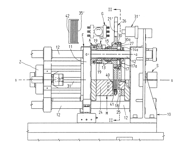
The illustrated mold closing unit F is used in an
injection molding machine for synthetic material. Thereby an
iniection molding unit basically injects synthetic material
into the mold cavity, which is constituted by second mold
parts 2~, 25, that can be set in close-position by closing
209A071
cylinders Z. During this process the second mold parts 24,
25, are located between a stationary mold carrier 10 and a
movable mold carrier ~1, that are interconnected by guide
rods 12. The movable mold carrier 11 is guided on the guide
rods 12, which are supported by the stationary mold carrier
10 .
Furthermore two identical first parts of an
injection mold 34 are provided, which are alternately trans-
ferred to the spaGe ~etween the mold carriers 10, 11, of the
mold closing unit F, on a guideway f, running vertically
with respect to the closing direction s-s, substantially in
the parting plane of the mold closing unit for creation of an
injection mold M. Thereby the first parts of an iniection
mold 34 are connected with an oscillating crank 26. so that
they constitute a motional unit. Basically it is, of course,
possible to connect several parts of an injection mold so
that they constitute an oscillating crank with multiple arms.
As particularly appears in Figure 2, the oscillating crank
26, which surrounds the first parts of an injection mold 34,
2~ is rotatable around an axis transversally disposed with
respect to a guideway f.
Figure 1 reveals that the nearly flat first parts
of an injection mold 34 are arranged in nearly flat annular
fixings 26a provided with removal openings 18. Basically
the fixings as well as the first parts of an injection mold
34 must only have such a thickness to secure that the
2094071
- 12 -
moldings Z1, 21'. are properly held during the swivelling
movement. During the following mold closure the first parts
of an injection mold 34 center themselves in the injection
mold owing to their shape and as a result define the mold
c~vity 43 together with the second mold parts 24, 25. Of
course, it is also possible to produce moldings with a depth
that exceeds the thickness of the fixings 26a with this
mold closing unit. The only difference resulting is a larger
opening width between the injection cycles. Since the first
part of an injection mold is a part of the mold itself and
it is essential for the production of moldings of best
possible quality that all parts of the multipart injection
mold are fitted together exactly, a precise positioning of
the oscillating crank at the axis a-a results by the mold
closure itself. However, as an exact positioning of the
first part of an injection mold resting in the mold
stressing chamber causes that the molding outside the mold
cavity or at least outside the injection mold M is also
placed in its ex~ct position, the molding 2~' can be
precisely positioned in a simple way. This is particularly
desireable in case a grab G of a handling H is used. At the
same time precision requirements for the rest of the axis
are not high.
In the first example of the possible executions,
the oscillating crank 26 is pivoted at one guide rod 12 by
means of its hub. Another possibility to solve this task is
2~9407~
- 13 -
to dispose an axis directly at one of the mold carriers.
The oscillating crank is driven at the guide rod by a drive
unit A. As drive means for instance toothed wheels, toothed
racks or driving belts are used, which drive the oscillating
crank preferably at the external side in the area of the
hub. Especially the application of a toothed rack offers the
possibility to approach exact final positions, which then can
be stated more precisely by the self-centering of the first
parts of an injection mold. The guide rod is provided with a
bearing bush 14 that is placed around a slide bearing 13 and
constitutes the hub of the oscillating crank. The bearing
bush 14 is connected with the movable mold carrier 11 by
means of distance studs 19, partially movable in direction
towards the axis a-a. It is also possible to provide the
stationary mold carrier 10 with such an arrangement. To place
the arrangement at the movable mold carrier offers the
advantage that when the injection mold is opened the first
part of the injection mold is first detached from the
movable and then from the stationary mold carrier, which can
in addition be supported, if necessary, by arranging corres-
ponding undercuttings at one of the first part of an
injection mold or by spring means. In the end it is insigni-
ficant in which succession the first parts of an injection
mold placed at the oscillating crank are detached from the
mold carriers. The detachment can additionally be supported,
if necessary, if an ejector unit 31, used for a purpose not
2094071
- 14 -
intended, handles the first part of the iniection mold in
order to adjust the distance pre-determined by the distance
studs 19 bet,ween bearing bush and mold carrier. Figure 1
shows the detached position immediately before the real
injection process starts.
A~ shown in Figure 2 the oscillating crank 26 that
is provided with two swivel arms 26b describes a guideway f,
which is approximately elliptical. This is necessary on the
one hand in order to keep the mold stressing chamber as small
as possible and on the other hand to have enough space left
to go past the guide rods 12. This disadvantage is
consciously accepted, considering the costs which a larger
mold stressing chamber would involve. However, to achieve the
elliptical motion, it is necessary that the drive unit moves
an eccentric 15 by a planetary gear, which is in connection
with the oscillating crank 26. The planetary gear is
subsequently described more in detail on the basis of
Figures 3 and 4.
The toothed wheel work Aa of the drive unit is in
connection with the toothed wheel work 15a of the eccentric
15 by means of a toothed belt. If the eccentric 15 is turned,
a corresponding movement of the oscillating crank 26 is
produced, as is apparent by the arrows in Figure 2. This is
caused owing to the fact that the planet wheels 16 and 17,
that are interconnected are placed at the eccentric. During
the turning movement the toothed wheel work 16a of the
209407~
- 15 -
planetary wheel 16 bites into the toothed wheel work 14a of
the bearing bush 14, which is fixedly mounted on the guide
rod 12. This radial fixin~ is effected by the distance
studs 19. The other planet wheel 17 bites with its toothed
wheel work 17a into the toothed wheel work 30b of a toothed
ring 30, which is in connection with the oscillating crank
26. The parts 14, 15 and 30 are separated from each another
by bearings 28, 29. The toothed ring is closed by a crown 27
in direction towards the stationary mold carrier 10.
The proportion from the toothed wheel work of the
toothed ring 30 to the toothed wheel work 14a of the
bearing bush 14 has been settled upon 2:1, so that the first
parts of an injection mold 34 always can occupy identical
positions. As is apparent especially from Figure ~ the
toothed wheel work 15a is disposed concentrically and the
toothed ring 30 eccentrically through the guide rods 12
with respect to the axis a-a. Basically the guideway thereby
merely extends into the space behind the machine, so that the
operator's room in front of the machine is not endangered.
When the pieces are swivelled they are already finished from
injection-technical side. If necessary, the swivelling
movement or, especially when several parts of an injection
mold are used, the period between finishing and removing the
moldings can be used for cooling the moldings. The removal
process also can be supported by an auxiliary ejector unit
31'.
209~071
;
- 16 -
Aside from the first parts of an inject,ion mold 34
it is also possible to provide exchange parts 35' which
limit a part of the mold stressing chamber when the mold is
closed. For this purpose they are detachably mounted on the
movement unit, that is on the oscillating crank 26 and thus
can remain connected with the iniection mold M durin~ the
production of the moldings. While the exchange parts 35'
are connected with the injection mold M, the movement unit
can be applicated for the transport of moldings 21, 21'.
The exchange parts are held at the frontal sides of
the first parts of an injection mold 34 of the oscillating
crank 26 by negative pressure. As soon as the exchange part
35' has been swivelled into the injection mold, the mold is
closed, whereupon the negative pressure, which holds the
exchange part 35' in the oscillating crank, is completely
reduced and instead negative pressure is built up in the
second mold part 24 of the injection mold, whereby the
exchange pa~t 35' is held, hermetically sealing, at its
perimeter on the oRcillating crank 26. As Figure 6 reveals
the vacuum channels 41 associated to the oscillating crank
are located in an area in which the two second mold parts
24, 25 are separated by a certain distance, even after the
mold has been closed. The exchange part 35' is held at its
.; perimeter by the vacuum channels 41a. The vacuum channels
are open in the closing direction of the mold closing unit.
The openings of the vacuum channels 41a end radially more
~ . . .
209~71
- 17 -
outside in an area where no vacuum channels 40a are provided.
The vacuum channels 40a nearly cover completely one side of
the mold stressing chamber ~Fig.5). The negative pressure is
generated by the vacuum connection 41. The exchange part i5
handed over to the second mold part 24 when the mold closure
is realized. The vacuum channels 40a to which vacuum is
applied by the vacuum connection 40, are interconnected by
transversal links, which are not represented in the drawings.
As long as the negative pressure is maintained in the vacuum
channels 40a, the exchange part remains in the injection
mold. Only when, in reversion of the sequence described at
the beginning, the vaccum is rebuilt in the vacuum channels
41a, the exchange part 35' can be again exchanged.
Alternatively the exchange parts can be held at
the perimeter of the removal openings 18 in rubber lips, so
that they are transported by the same means, but independant
from the transport process for the moldings.
During the manufacturing process of the moldings
an injection molding unit S submerges with its nozzle into
a gate system 25b and the material is then supplied by a
sprue channel 25a.
As represented in Figure 1 a grab G is used for the
removal of the moldings 21, 21' and the exchange parts 35'.
Thereby a pile hopper may be associated with this grab, so
that the exchange parts 35' to be exchanged can be handed
over directly into the pile hopper by a turning of for
2094071
- 18 -
example 180. For instance sound recording discs in the CD
production come into question for example.
Figure 7 shows a further possible execution, which
differs from the first example because of the arrangement of
the swiv~lling axis for the oscillating crank 26 and the kind
of drive. The swivelling axis including slide bearing 13' and
bearing bush 14' is not placed anymore at one guide rod 12,
through which the space requirements are minimized. However,
to avoid a collision with the guide rods, the swivelling arm
is mounted symetrically with respect to plane b-b and
disposes of recesses 26c, which alternately border on the
guide rod. Thereby as drive A a linear drive L is used,
whose linear movements are converted into rotation ~y the
toothed quadrant disc 45 and the toothed wheel 46. Driving
belts may be used as well instead of the linear drives.